EP0835807A1 - Dispositif pour encercler un faisceau de câbles - Google Patents
Dispositif pour encercler un faisceau de câbles Download PDFInfo
- Publication number
- EP0835807A1 EP0835807A1 EP97117399A EP97117399A EP0835807A1 EP 0835807 A1 EP0835807 A1 EP 0835807A1 EP 97117399 A EP97117399 A EP 97117399A EP 97117399 A EP97117399 A EP 97117399A EP 0835807 A1 EP0835807 A1 EP 0835807A1
- Authority
- EP
- European Patent Office
- Prior art keywords
- slide rod
- carriage
- guided
- slide
- tool
- Prior art date
- Legal status (The legal status is an assumption and is not a legal conclusion. Google has not performed a legal analysis and makes no representation as to the accuracy of the status listed.)
- Granted
Links
Images
Classifications
-
- B—PERFORMING OPERATIONS; TRANSPORTING
- B65—CONVEYING; PACKING; STORING; HANDLING THIN OR FILAMENTARY MATERIAL
- B65B—MACHINES, APPARATUS OR DEVICES FOR, OR METHODS OF, PACKAGING ARTICLES OR MATERIALS; UNPACKING
- B65B13/00—Bundling articles
- B65B13/02—Applying and securing binding material around articles or groups of articles, e.g. using strings, wires, strips, bands or tapes
- B65B13/025—Hand-held tools
- B65B13/027—Hand-held tools for applying straps having preformed connecting means, e.g. cable ties
Definitions
- the invention relates to a tool for binding an object, in particular a wire harness, by means of a tape.
- the tool includes a tool body, one therein guided pusher bar that puts the tape in a wrapping position around the to be tied Object pushes, and a drive device for the slide rod.
- the invention has for its object to a tool of the type mentioned create, in which the tape feed from that single shaft revolution per Game is derived, which is based on the control of the other movements.
- the Solution according to the invention consists in the features of claim 1 and preferably those of the subclaims.
- a special gear which is capable of a crank circulation to transform into a translational movement, the length of which is substantially greater than that Crank diameter is. This is necessary because it limits the crank diameter is that the tool should have the smallest possible transverse dimensions during the translational movement is large, namely at least the extent of the tape length used got to.
- the crank can with the mentioned cam (or what else to drive the other tool functions is provided). You can on the same Wave sit, but this is not necessary; it does not even need to rotate in the same direction to have. It is crucial that - just like the cam disk - it rotates one revolution per cycle makes.
- the crank movement is on a slide that moves along an elongated guide transfer. This is conveniently done using a connecting rod.
- the crank can but also attack directly on the sled, for example with one in the sled interacts transversely to the direction of movement provided sliding groove.
- the sled carries at least one small gear, which is referred to here as a pinion, and which attaches itself rolls a track that is provided parallel to the slide guide. This will make it of the carriage movement. Its peripheral speed at its that of The side facing away from the track is twice the size of the tool body of the sled. If it interacts directly with the pushrod there, it becomes therefore a feed rate twice that of the carriage and a corresponding one awarded twice the distance of movement.
- the pinion is not directly, but via another, larger gearwheel the slide rod cooperates, which is arranged coaxially with the pinion and rotatably with connected to it and its circumferential speed corresponding to the career the diameter ratio is higher, so that the feed speed and Feed distance of the slide rod is increased accordingly.
- the gear wheels, the track and the slide rod are preferably toothed; however, the execution in the form of a friction gear or the like should be protected not be excluded.
- an abutment is provided on which the slide rod is opposite to the Gear engagement supports, this abutment is advantageously provided on the carriage and is designed as a roller in order to reduce the friction.
- a straight stretch of the slide rod is possible.
- one would such execution require that the tool body, the belt and the pusher rod in a row, at least twice as long as the tape. More appropriate is therefore a flexible design of the slide rod, which is guided by a 180 ° deflection is, as is known per se (DE-C 40 35 968).
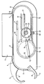
- the elongated tool body 1 carries two pliers parts 2, 3 at its front end, which are movable in such a way that the pliers are opened to receive a bundle of cables and can then be closed.
- the band 6 has an elongated, facing the front of the tool body Tongue and at the rear end a band lock 7. The one in the front area of the tool body When the pliers 2, 3 are closed, the band channel 4 runs in a curved manner formed in the pliers parts guide groove 8.
- the band 6 is fed in the band channel 4 by means of a flexible slide rod 10, which is movably guided in its longitudinal direction in a slide rod guide channel 11 is.
- the slide rod guide channel 11 connects to the band channel 4. If the Push rod 10 is advanced, it enters the band channel 4 and pushes the band to position 9.
- the drive of the slide rod is derived from a crank, which is driven by a crank pin 12 and a dash-dotted circle 13 is symbolized by the crank pin 12 during of a working cycle.
- the crank drives one via a connecting rod 14 Slide 15, which is guided in a straight line by a guide hatched by the back Guide surfaces 16, 17 is indicated in the drawing, which with the side surfaces of the Slide 15 interact. It is understood that the practical implementation is different can be. With regard to the frictional forces, it can e.g. B. be more appropriate to to provide ships with rollers that run in a guide groove.
- a bearing is provided on the ships 15 for the common axis 18 of a gear wheel 19 and a pinion 20, the latter in the drawing only by its Circumferential lines and its pitch circle is indicated.
- the two wheels are non-rotatable with each other connected.
- the toothed circumference of the pinion 20 meshes with one in the tool body fixed and parallel to the guide 16, 17 arranged rack 21.
- This meshes with the gear rack 21 opposite side with the slide rod 10 designed as a rack is supported in the area of engagement of the gear wheel 19 by a roller 22 which on a projection 23 connected to the carriage 15 is mounted.
- crank 12, 13 can also be used to drive or control other processes will. So it is suitable in its transverse to the longitudinal direction of the tool body Movement range for advancing one provided in or on the magazine 5 Revolver drum that transfers the tapes into the tape guide channel 4.
- the feed distance of the slide rod 10 is composed of the movement distance the carriage 15, which is the same diameter as the crank 12, 13, and the feed distance, which is given by the gear 19. This is about the diameter ratio of the two Gears two times larger than the slide movement distance.
- a feed path that is four to eight times larger than the crank diameter, can be easily with this principle realize.
Landscapes
- Engineering & Computer Science (AREA)
- Mechanical Engineering (AREA)
- Basic Packing Technique (AREA)
- Insulated Conductors (AREA)
- Installation Of Indoor Wiring (AREA)
Applications Claiming Priority (2)
| Application Number | Priority Date | Filing Date | Title |
|---|---|---|---|
| DE29617653U | 1996-10-10 | ||
| DE29617653U DE29617653U1 (de) | 1996-10-10 | 1996-10-10 | Werkzeug zum Binden eines Kabelbaums |
Publications (2)
| Publication Number | Publication Date |
|---|---|
| EP0835807A1 true EP0835807A1 (fr) | 1998-04-15 |
| EP0835807B1 EP0835807B1 (fr) | 2003-01-02 |
Family
ID=8030417
Family Applications (1)
| Application Number | Title | Priority Date | Filing Date |
|---|---|---|---|
| EP97117399A Expired - Lifetime EP0835807B1 (fr) | 1996-10-10 | 1997-10-08 | Dispositif pour encercler un faisceau de câbles |
Country Status (6)
| Country | Link |
|---|---|
| US (1) | US5934341A (fr) |
| EP (1) | EP0835807B1 (fr) |
| JP (1) | JP3209412B2 (fr) |
| DE (2) | DE29617653U1 (fr) |
| ES (1) | ES2189911T3 (fr) |
| PT (1) | PT835807E (fr) |
Cited By (1)
| Publication number | Priority date | Publication date | Assignee | Title |
|---|---|---|---|---|
| CN104085558A (zh) * | 2014-06-18 | 2014-10-08 | 浙江松盛金属制品有限公司 | 扁钢码垛打包一体装置 |
Families Citing this family (8)
| Publication number | Priority date | Publication date | Assignee | Title |
|---|---|---|---|---|
| US7334610B2 (en) * | 2004-10-13 | 2008-02-26 | Panduit Corp. | Harness board fixture |
| US7458398B2 (en) * | 2005-10-20 | 2008-12-02 | Panduit Corp. | Metal tie tool with rotary gripper and ball setting device |
| WO2007048109A1 (fr) * | 2005-10-20 | 2007-04-26 | Panduit Corp. | Outil a attache metallique comprenant une pince rotative et dispositif pour installer une balle |
| JP4820634B2 (ja) * | 2005-12-05 | 2011-11-24 | ヘラマンタイトン株式会社 | 外部駆動型結束工具及び人力駆動式定置型結束装置 |
| JP4796870B2 (ja) * | 2006-03-06 | 2011-10-19 | ヘラマンタイトン株式会社 | 結束工具駆動用人力装置 |
| US8051881B2 (en) * | 2008-04-01 | 2011-11-08 | Panduit Corp. | Metal retained tension tie tool |
| US20100139805A1 (en) * | 2008-12-10 | 2010-06-10 | Panduit Corp. | Power Tool for Stainless Steel Metal Locking Ties |
| TWI516415B (zh) | 2008-12-12 | 2016-01-11 | 美克司股份有限公司 | 鐵筋捆紮機 |
Citations (4)
| Publication number | Priority date | Publication date | Assignee | Title |
|---|---|---|---|---|
| DE8913511U1 (de) | 1989-11-15 | 1991-03-14 | Paul Hellermann GmbH, 25421 Pinneberg | Vorrichtung zum Umschlingen eines zu bindenden Gegenstands, beispielsweise eines Kabelbaums |
| EP0428116A1 (fr) | 1989-11-15 | 1991-05-22 | Paul Hellermann GmbH | Bande et outil de cerclage et de tension pour objets allongés |
| US5167265A (en) * | 1991-07-05 | 1992-12-01 | Kyoichi Limited | Hand-operated binding device |
| DE9214901U1 (de) | 1992-11-02 | 1994-03-03 | Paul Hellermann GmbH, 25421 Pinneberg | Werkzeug zum Binden eines Gegenstands mittels eines Bandes |
Family Cites Families (1)
| Publication number | Priority date | Publication date | Assignee | Title |
|---|---|---|---|---|
| US3891012A (en) * | 1973-10-23 | 1975-06-24 | Amp Inc | Apparatus for applying ties to bundles |
-
1996
- 1996-10-10 DE DE29617653U patent/DE29617653U1/de not_active Expired - Lifetime
-
1997
- 1997-10-08 DE DE59709047T patent/DE59709047D1/de not_active Expired - Lifetime
- 1997-10-08 PT PT97117399T patent/PT835807E/pt unknown
- 1997-10-08 JP JP27572397A patent/JP3209412B2/ja not_active Expired - Lifetime
- 1997-10-08 ES ES97117399T patent/ES2189911T3/es not_active Expired - Lifetime
- 1997-10-08 EP EP97117399A patent/EP0835807B1/fr not_active Expired - Lifetime
- 1997-10-09 US US08/947,837 patent/US5934341A/en not_active Expired - Lifetime
Patent Citations (5)
| Publication number | Priority date | Publication date | Assignee | Title |
|---|---|---|---|---|
| DE8913511U1 (de) | 1989-11-15 | 1991-03-14 | Paul Hellermann GmbH, 25421 Pinneberg | Vorrichtung zum Umschlingen eines zu bindenden Gegenstands, beispielsweise eines Kabelbaums |
| EP0428116A1 (fr) | 1989-11-15 | 1991-05-22 | Paul Hellermann GmbH | Bande et outil de cerclage et de tension pour objets allongés |
| DE4035968C2 (de) | 1989-11-15 | 1994-04-14 | Hellermann Gmbh P | Vorrichtung zum Umschlingen eines zu bindenden Gegenstands, beispielsweise eines Kabelbaums |
| US5167265A (en) * | 1991-07-05 | 1992-12-01 | Kyoichi Limited | Hand-operated binding device |
| DE9214901U1 (de) | 1992-11-02 | 1994-03-03 | Paul Hellermann GmbH, 25421 Pinneberg | Werkzeug zum Binden eines Gegenstands mittels eines Bandes |
Cited By (2)
| Publication number | Priority date | Publication date | Assignee | Title |
|---|---|---|---|---|
| CN104085558A (zh) * | 2014-06-18 | 2014-10-08 | 浙江松盛金属制品有限公司 | 扁钢码垛打包一体装置 |
| CN104085558B (zh) * | 2014-06-18 | 2016-04-20 | 浙江松盛金属制品有限公司 | 扁钢码垛打包一体装置 |
Also Published As
| Publication number | Publication date |
|---|---|
| DE29617653U1 (de) | 1998-02-05 |
| US5934341A (en) | 1999-08-10 |
| ES2189911T3 (es) | 2003-07-16 |
| JPH10119921A (ja) | 1998-05-12 |
| PT835807E (pt) | 2003-04-30 |
| JP3209412B2 (ja) | 2001-09-17 |
| EP0835807B1 (fr) | 2003-01-02 |
| DE59709047D1 (de) | 2003-02-06 |
Similar Documents
| Publication | Publication Date | Title |
|---|---|---|
| DE1296087B (de) | Verfahren zur Versetzung einer Last und Vorrichtung zur Durchfuehrung des Verfahrens | |
| EP0835807B1 (fr) | Dispositif pour encercler un faisceau de câbles | |
| DE836905C (de) | Drehkopf zum Ablegen von Faserbaendern in Kannen an Krempeln, Strecken, Kaemmaschinen od. dgl. | |
| DE2748820B2 (de) | Vorrichtung zum Quertrennen oder Querperforieren von Materialbahnen | |
| DE3128043C2 (de) | Vorrichtung zum Verpacken von Pulver, Granulaten, stückigen, pastösen und flüssigen Verpackungsgütern mittels einer schlauchförmigen Folie | |
| DD283352A5 (de) | Vorrichtung zum schneiden einer kontinuierlich durchlaufenden platte, besonders aus asbestzement- oder aehnlichen materialien | |
| EP0835808B1 (fr) | Dispositif pour encercler un faisceau de câbles | |
| DE202009016214U1 (de) | Vorrichtung zum Auf- und Abwickeln von strangartigem Wickelgut | |
| DE2210983A1 (de) | Verfahren und Vorrichtung zur Montage von Einfach- und Mehrfach-Antriebsrollenketten | |
| DE19950401B4 (de) | Vorrichtung zum Drehen von auf einer Federwindemaschine hergestellten Federn | |
| DE2219411C3 (de) | Stoff-Zuführvorrichtung für Auslegemaschinen | |
| DE19605647A1 (de) | Bearbeitungsmaschine | |
| DE2556444C3 (de) | Vorschubeinrichtung für stab- bzw. bandförmiges Material | |
| DE3133149C2 (de) | Legemaschine | |
| DE2821135C2 (de) | Vorrichtung zum Fortschalten des Farbbandes einer Endlosfarbbandkassette | |
| CH669342A5 (fr) | ||
| DD201578A5 (de) | Bandwickelmaschine | |
| DE3012023A1 (de) | Geraet zum gewickeln von rohren, kabeln o.dgl. | |
| DE3148473C2 (fr) | ||
| DE3615750A1 (de) | Durchstosseinrichtung | |
| DE19611589C2 (de) | Zahnriemengetriebe | |
| DE2525302C3 (de) | Ofen für eine Anlage zur Wärmebehandlung eines Metallbandes | |
| DE2730727C2 (de) | Bandauszugsvorrichtung für ein Magnetbandkassettengerät, insbesondere ein Videobandgerät | |
| DE2064227B2 (de) | Vorrichtung fur die Zufuhrung von Schußfaden zu einer Kettenwirkmaschine | |
| DE552004C (de) | Maschine zur Herstellung von Sprungfedern mit verknoteter Einwindung und Einrichtung zum Zufuehren der fertigen Federn an eine Sammelstelle |
Legal Events
| Date | Code | Title | Description |
|---|---|---|---|
| PUAI | Public reference made under article 153(3) epc to a published international application that has entered the european phase |
Free format text: ORIGINAL CODE: 0009012 |
|
| AK | Designated contracting states |
Kind code of ref document: A1 Designated state(s): DE ES FR GB IT PT SE |
|
| AX | Request for extension of the european patent |
Free format text: AL;LT;LV;RO;SI |
|
| 17P | Request for examination filed |
Effective date: 19980728 |
|
| AKX | Designation fees paid |
Free format text: DE ES FR GB IT PT SE |
|
| RBV | Designated contracting states (corrected) |
Designated state(s): DE ES FR GB IT PT SE |
|
| GRAG | Despatch of communication of intention to grant |
Free format text: ORIGINAL CODE: EPIDOS AGRA |
|
| RTI1 | Title (correction) |
Free format text: TOOL FOR TYPING A BUNDLE OF CABLES |
|
| 17Q | First examination report despatched |
Effective date: 20011205 |
|
| RAP1 | Party data changed (applicant data changed or rights of an application transferred) |
Owner name: HELLERMANNTYTON GMBH |
|
| GRAG | Despatch of communication of intention to grant |
Free format text: ORIGINAL CODE: EPIDOS AGRA |
|
| GRAH | Despatch of communication of intention to grant a patent |
Free format text: ORIGINAL CODE: EPIDOS IGRA |
|
| GRAH | Despatch of communication of intention to grant a patent |
Free format text: ORIGINAL CODE: EPIDOS IGRA |
|
| GRAA | (expected) grant |
Free format text: ORIGINAL CODE: 0009210 |
|
| AK | Designated contracting states |
Kind code of ref document: B1 Designated state(s): DE ES FR GB IT PT SE |
|
| REG | Reference to a national code |
Ref country code: GB Ref legal event code: FG4D Free format text: 20030102:NOT ENGLISH |
|
| REF | Corresponds to: |
Ref document number: 59709047 Country of ref document: DE Date of ref document: 20030206 Kind code of ref document: P |
|
| REG | Reference to a national code |
Ref country code: PT Ref legal event code: SC4A Free format text: AVAILABILITY OF NATIONAL TRANSLATION Effective date: 20030307 |
|
| GBT | Gb: translation of ep patent filed (gb section 77(6)(a)/1977) |
Effective date: 20030428 |
|
| REG | Reference to a national code |
Ref country code: ES Ref legal event code: FG2A Ref document number: 2189911 Country of ref document: ES Kind code of ref document: T3 |
|
| ET | Fr: translation filed | ||
| PLBE | No opposition filed within time limit |
Free format text: ORIGINAL CODE: 0009261 |
|
| STAA | Information on the status of an ep patent application or granted ep patent |
Free format text: STATUS: NO OPPOSITION FILED WITHIN TIME LIMIT |
|
| 26N | No opposition filed |
Effective date: 20031003 |
|
| REG | Reference to a national code |
Ref country code: FR Ref legal event code: PLFP Year of fee payment: 19 |
|
| REG | Reference to a national code |
Ref country code: FR Ref legal event code: PLFP Year of fee payment: 20 |
|
| PGFP | Annual fee paid to national office [announced via postgrant information from national office to epo] |
Ref country code: PT Payment date: 20160923 Year of fee payment: 20 |
|
| PGFP | Annual fee paid to national office [announced via postgrant information from national office to epo] |
Ref country code: GB Payment date: 20161025 Year of fee payment: 20 Ref country code: FR Payment date: 20161025 Year of fee payment: 20 Ref country code: DE Payment date: 20161027 Year of fee payment: 20 |
|
| PGFP | Annual fee paid to national office [announced via postgrant information from national office to epo] |
Ref country code: SE Payment date: 20161025 Year of fee payment: 20 Ref country code: IT Payment date: 20161025 Year of fee payment: 20 Ref country code: ES Payment date: 20161025 Year of fee payment: 20 |
|
| REG | Reference to a national code |
Ref country code: DE Ref legal event code: R071 Ref document number: 59709047 Country of ref document: DE |
|
| REG | Reference to a national code |
Ref country code: GB Ref legal event code: PE20 Expiry date: 20171007 |
|
| PG25 | Lapsed in a contracting state [announced via postgrant information from national office to epo] |
Ref country code: GB Free format text: LAPSE BECAUSE OF EXPIRATION OF PROTECTION Effective date: 20171007 Ref country code: PT Free format text: LAPSE BECAUSE OF EXPIRATION OF PROTECTION Effective date: 20171017 |
|
| REG | Reference to a national code |
Ref country code: ES Ref legal event code: FD2A Effective date: 20180508 |
|
| PG25 | Lapsed in a contracting state [announced via postgrant information from national office to epo] |
Ref country code: ES Free format text: LAPSE BECAUSE OF EXPIRATION OF PROTECTION Effective date: 20171009 |