EP0835831A1 - Rotations-Transportvorrichtung zur Weitergabe von Gegenständen - Google Patents
Rotations-Transportvorrichtung zur Weitergabe von Gegenständen Download PDFInfo
- Publication number
- EP0835831A1 EP0835831A1 EP97107589A EP97107589A EP0835831A1 EP 0835831 A1 EP0835831 A1 EP 0835831A1 EP 97107589 A EP97107589 A EP 97107589A EP 97107589 A EP97107589 A EP 97107589A EP 0835831 A1 EP0835831 A1 EP 0835831A1
- Authority
- EP
- European Patent Office
- Prior art keywords
- holding
- axis
- transport device
- rotary transport
- jaws
- Prior art date
- Legal status (The legal status is an assumption and is not a legal conclusion. Google has not performed a legal analysis and makes no representation as to the accuracy of the status listed.)
- Granted
Links
- 230000033001 locomotion Effects 0.000 claims abstract description 54
- 238000012546 transfer Methods 0.000 claims description 39
- 238000004806 packaging method and process Methods 0.000 claims description 17
- 238000012856 packing Methods 0.000 claims description 10
- 238000011144 upstream manufacturing Methods 0.000 claims description 6
- 238000006073 displacement reaction Methods 0.000 claims description 3
- 230000001360 synchronised effect Effects 0.000 claims description 3
- 230000013011 mating Effects 0.000 claims 1
- 235000009508 confectionery Nutrition 0.000 description 34
- 210000003128 head Anatomy 0.000 description 30
- 230000015572 biosynthetic process Effects 0.000 description 6
- 235000013736 caramel Nutrition 0.000 description 4
- 238000013461 design Methods 0.000 description 4
- 230000005540 biological transmission Effects 0.000 description 3
- 230000002093 peripheral effect Effects 0.000 description 3
- 238000001514 detection method Methods 0.000 description 2
- 238000000034 method Methods 0.000 description 2
- 210000000056 organ Anatomy 0.000 description 2
- 238000003860 storage Methods 0.000 description 2
- 238000013459 approach Methods 0.000 description 1
- 230000009286 beneficial effect Effects 0.000 description 1
- 239000000969 carrier Substances 0.000 description 1
- 229940112822 chewing gum Drugs 0.000 description 1
- 235000015218 chewing gum Nutrition 0.000 description 1
- 230000008878 coupling Effects 0.000 description 1
- 238000010168 coupling process Methods 0.000 description 1
- 238000005859 coupling reaction Methods 0.000 description 1
- 238000009826 distribution Methods 0.000 description 1
- 210000001061 forehead Anatomy 0.000 description 1
- 238000003780 insertion Methods 0.000 description 1
- 230000037431 insertion Effects 0.000 description 1
- 238000004519 manufacturing process Methods 0.000 description 1
- 239000005022 packaging material Substances 0.000 description 1
- 238000003825 pressing Methods 0.000 description 1
- 238000012545 processing Methods 0.000 description 1
- 238000012549 training Methods 0.000 description 1
- 238000010626 work up procedure Methods 0.000 description 1
Images


Classifications
-
- B—PERFORMING OPERATIONS; TRANSPORTING
- B65—CONVEYING; PACKING; STORING; HANDLING THIN OR FILAMENTARY MATERIAL
- B65G—TRANSPORT OR STORAGE DEVICES, e.g. CONVEYORS FOR LOADING OR TIPPING, SHOP CONVEYOR SYSTEMS OR PNEUMATIC TUBE CONVEYORS
- B65G47/00—Article or material-handling devices associated with conveyors; Methods employing such devices
- B65G47/74—Feeding, transfer, or discharging devices of particular kinds or types
- B65G47/84—Star-shaped wheels or devices having endless travelling belts or chains, the wheels or devices being equipped with article-engaging elements
- B65G47/846—Star-shaped wheels or wheels equipped with article-engaging elements
- B65G47/847—Star-shaped wheels or wheels equipped with article-engaging elements the article-engaging elements being grippers
-
- B—PERFORMING OPERATIONS; TRANSPORTING
- B65—CONVEYING; PACKING; STORING; HANDLING THIN OR FILAMENTARY MATERIAL
- B65B—MACHINES, APPARATUS OR DEVICES FOR, OR METHODS OF, PACKAGING ARTICLES OR MATERIALS; UNPACKING
- B65B35/00—Supplying, feeding, arranging or orientating articles to be packaged
- B65B35/10—Feeding, e.g. conveying, single articles
- B65B35/26—Feeding, e.g. conveying, single articles by rotary conveyors
Definitions
- the invention relates to a rotary transport device for Transfer of objects, especially for packaging machines, with a basic housing rotatable about a stationary axis, the a plurality of pairs of holding jaws for receiving an object between oppositely axially movable holding jaws a pair of holding jaws, each pair of holding jaws around a substantially parallel to the stationary axis extending axis of rotation jointly pivoted and a motion control device for the pairs of holding jaws for connection with a cam arrangement accommodated on the stationary axis is provided.
- the outer holding jaw of a pair of holding jaws to control their axial and pendulum movement by one Central axis of rotation parallel to a shaft to be fixed, the axially displaceable in a hollow shaft or sleeve is stored.
- the hollow shaft or sleeve rotatably supports the inner one Holding jaw of the pair of holding jaws and is in the housing of the gripper or transfer wheel rotating around the stationary central axis pivotally arranged.
- the shaft receives its axial movement for opening and closing the pair of holding jaws by scanning a stationary control curve.
- the swivel movement for the inner shaft connected to the outer holding jaw is also via the swivel control device for the swivel movement derived from the hollow shaft or sleeve for the inner holding jaw (DE-A-3820139, WO 93/25440).
- the invention is therefore based on the object of a rotary transport device to pass on objects of the beginning mentioned type to improve, such that while maintaining the previous advantages in terms of speed adjustment of the pairs of holding jaws on the upstream feed or downstream discharge organs a change in position of the objects possible with respect to the rotating transport device should be so that the objects e.g. in a first orientation recorded and given in a second orientation can be.
- This task is carried out in a rotary transport device aforementioned type according to the invention solved in that at least one of the jaws of each pair of jaws relative to that Axis of rotation is rotatable about a holding jaw axis.
- the solution according to the invention makes it possible to add one for joint swivel control, each movable on the rotating one Carrier pair of holding jaws, the holding jaws itself to allow an independent rotational movement that it allows during the transportation of the item the transport device itself, e.g. a transfer head one Packaging machine, the object around its axis of storage, e.g. from a flat position to an upright position or vice versa and in this way twist the object suitably, e.g. for a subsequent group or bar formation.
- the holding jaws are rotatably connected to a toothed segment, preferably provided integrally in one piece with this on the circumference, and with this tooth segment is a counter-tooth segment of the movement control device in meshing.
- Basic housing a plurality of about the respective axis of rotation swiveling swivel housing, in which one on both sides Radial plane one holding jaw of a pair of holding jaws around the Holding jaw axis is rotatably mounted.
- a pair is spaced for each pair of jaws
- Counter-tooth segments in meshing engagement with the tooth segments of the pair of holding jaws and the counter-tooth segments are about the axis of rotation of the pair of holding jaws, which are also the The pivot axis of the swivel housing is pivotable.
- the axis of rotation of the pairs of holding jaws (at the same time Pivot axis of each swivel housing) formed by a shaft, on the one counter tooth segment rotatably for engagement with the one Holding jaw is received while the counter-tooth segment for engagement with the other holding jaw of the pair of holding jaws rotatably connected to a sleeve concentrically surrounding the shaft is.
- the holding jaws with the tooth segments are preferably through the counter-tooth segments for the rotation control of the holding jaws also axially oppositely displaceable, with the purpose of Gearing engagement between the tooth segments of the holding jaws and the counter-tooth segments of the rotary actuator for the holding jaws are trapped in a cage that goes through sideways arranged cover plates is formed.
- the stationary axis with the cam arrangement for the movement control of the pairs of holding jaws and the Swivel housing can be turned through 180 °.
- the cam arrangement consists preferably of a plurality of non-rotatably with the cam plates connected to the stationary axis.
- Retaining fingers are provided for supporting the object, wherein the holding finger preferably in the area of the radial plane is arranged and for synchronous movement with the swivel housing controllable by a groove curve via a rotatably mounted lever is.
- the basic housing all-round holding finger housing for driving the holding finger preferably opposite to that the motion control device for the pairs of holding jaws as well as for the swivel control the basic housing accommodating the swivel housing is arranged, with the swivel housing between and holding finger housing.
- the transport device finds a preferred use as a transfer head for receiving packaged, individual items Items from an upstream, in sync with the Circulation speed of the transfer head and for, in particular by 90 ° with respect to a recording position twisted forwarding of items to the individual Objects in groups of stacking belt conveyors.
- a transfer head 1 schematically in a packaging machine system explained that for the packaging of candies 205 by prismatic Geometry, e.g. of soft caramels is provided without that the embodiment is limited to such products would.
- the transfer head 1 provided the, downstream of the packing head 2 and arranged upstream of a stacking belt conveyor 3, likewise has a housing 102 rotating about a stationary axis 101, on the pair of jaws pivotally mounted about axes of rotation 103 104 are pivotally mounted, rotated 90 ° in relation on the orientation of the pairs of pack jaws 204 of the pack head 2 arranged to hold the individually wrapped candies 205 of the same speed, but with opposite direction of rotation rotating packing head 2 and for delivery are provided on a stacking belt conveyor 3, the with significantly lower conveying speed (approx. 1/3 of the circulating speed of the rotating housing 102 of the transfer head 1 the individually wrapped candies in groups (here e.g.
- the stacking belt conveyor points to the formation of the groups 3 shows a stacking belt 301 with drivers 302, the stacking belt is guided over a deflection roller 303 and in the area the reception of the candies 205 from the transfer head 1 and Further transport of the candy groups has a counter bearing 304.
- the sweets On the way of receiving the candies 205 from the packing head 2 by the pairs of holding jaws 104 of the transfer head 1 the sweets must be delivered to the stacking belt conveyor 3 205 therefore still 90 ° with simultaneous detection by the Holding jaw pairs 104 are rotated. Preferably done this rotational movement only at the end, i.e. together with one opposing axial movement of the pairs of holding jaws 104 for Release of the candy 205 to the stacking belt 301 of the stacking belt conveyor 3, so that the jaw pairs 104 not just one Subject to axial movement, but at the same time by one Rotational movement of the pairs of holding jaws 104 is superimposed, for rotating the candies 205 in the upright position.
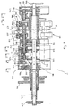
- the design of the transfer head 1 is shown below with the device for rotating the pairs of holding jaws 104 1-9 explained in more detail.
- the transfer head 1 has the central, stationary, however axis 101 rotatable in the circumferential direction, in particular by 180 ° on, which is between a stationary housing 107 and a Bearing plate 108 extends.
- On the stationary axis 101 is rotatably connected to the axis 101, a cam arrangement 109 as part of a motion control device for the holding jaw pairs 104 fixed.
- This cam arrangement 109 consists of a plurality of on the stationary axis 101 cam disks 110, 111, 112, 113 arranged in sequence, 114. They are preferred together with the stationary axis 106 swivels through 180 ° to change the movement pattern for a rotating movement of the individual pairs of holding jaws 104 set up, as will be explained below becomes.
- cam plates 110-114 could also be structurally united or separately via e.g. a common adjusting sleeve, which are rotatably received on the stationary axis 106 is adjustable relative to this by a certain angle be.
- Opposing swivel housing 117 is a pair of holding jaws 104 with the holding jaws 104a, 104b, wherein each holding jaw 104a, 104b is axially movable around the candy 205 pressing on opposing surfaces with frictional engagement and grip by a spring 106 or to release.
- the holding jaws 104a, 104b are also one Holding jaw axis A rotatable around the gripped candy 205 (or another item that is being processed) in a position opposite the receiving position, preferably by 90 ° forward the rotated position (e.g. upright after flat recording).
- the motion control device for each pair of holding jaws 104, the holding jaws 104a, 104b both opposing Axial movement as well as a rotary movement around their Gives the jaw axis A, the cams 110, 111, 112, the cams 111 and 112 the axial movement the outer holding jaw 104b (cam disk 111) or the axial movement of the inner holding jaw 104a (cam disc 112) control.
- the control of the axial movement for the inner holding jaw 104a takes place via the control roller of the also by radial Guide body 123 radially guided cam lever 122 on the Sleeve 124, with which the radial guide body 123 rotatably are connected, the sleeve 124 with the inner holding jaw 104a for transmitting the axial movement from the sleeve 124 is directly connected to this holding jaw 104a.
- the cam lever 122 is in insert with its other end 115 of the base housing 102 rotatably mounted.
- pivotable Holding jaw pairs 104 also additionally with a rotary movement to equip the holding jaw axis A to the opposite a pick-up position from the upstream packing head 1 e.g. delivery position for candies 205 rotated by 90 ° each holding jaw 104a, 104b in one piece with a tooth segment 126, 127 provided that in meshing engagement with counter-tooth segments 128, 129, which is once non-rotatable for the outer holding jaw 104b on the shaft 125 or for the inner holding jaw 104a are received on the sleeve 124.
- FIG. 9 The partial sectional view of FIG. 9 (with removed Swivel housing cover) once again illustrates the holding jaws 104a, 104b of the transfer head 1 additionally awarded Degree of freedom and shows the transmission elements for the Transfer of an additional rotary movement, here to the outside Holding jaw 104b about the holding jaw axis A, wherein it can be seen that by an integral connection of the toothed segment 127 with the holding jaw 104b of this by meshing with the counter-toothed segment 129, a rotary movement about the holding jaw axis A can be awarded when the shaft is twisted 125, with which the counter-tooth segment 129 is firmly connected.
- the gap is a holding finger for each swivel housing 117 137 in a central radial plane B between the two holding jaws 104a, 104b, practically in plant or immediately adjacent provided for the respective article, here candy 205, the reliable support and handover of the candy 205 from the transfer head 1 to the successor device, here the stacking belt 301 of the stacking belt conveyor 3 is supported.
- FIG. 11a and 11b schematically the transfer of the individually wrapped candies (205) from the transfer head 1 for one Holding jaw pair shown schematically, in Fig. 11a for the formation of groups for upright packaging and in Fig. 11b for forming groups in a flat pack, in particular for Fig. 11a it is clear that the rotational movement of the holding jaws 104a, 104b about the holding jaw axis A in the area of the Transfer to the stacking belt conveyor 3, i.e. under superimposition the pivoting movement that the holding jaws 104a, 104b with the Execute swivel housing 117, done.
- the thrust bearing 304 has an insertion slope 304a and the holding finger 137 stands if necessary, ready to support the handover process.
- Group A, B is then moved by driver 302 along the counter holder in a packing compartment 305 thus formed promoted away.
Landscapes
- Engineering & Computer Science (AREA)
- Mechanical Engineering (AREA)
- Specific Conveyance Elements (AREA)
Abstract
Description
- Fig. 1
- einen Längsschnitt durch einen Übergabekopf in einer Bonbon-Verpackungsmaschine,
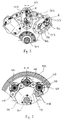
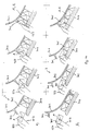
- Fig. 2
- eine Teilschnitt-Darstellung entlang einer Linie A-A nach Fig.1,
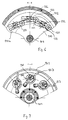
- Fig. 3
- eine Teilschnitt-Darstellung entlang einer Linie B-B nach Fig. 1,
- Fig. 4
- eine Teilschnitt-Darstellung entlang einer Linie C-C nach Fig.1,
- Fig. 5
- eine Teilschnitt-Darstellung entlang einer Linie D-D nach Fig. 1,
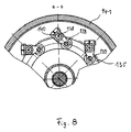
- Fig. 6
- eine Teilschnitt-Darstellung entlang einer Linie E-E nach Fig.1,
- Fig. 7
- eine Teilschnitt-Darstellung entlang einer Linie F-F nach Fig. 1,
- Fig. 8
- eine Teilschnitt-Darstellung entlang einer Linie G-G nach Fig.1,
- Fig. 9
- eine Ansicht ähnlich derjenigen in Fig. 2 für eine einzelne Haltebacke (äußere Axialansicht), und
- Fig. 10
- eine Prinzipdarstellung des Einsatzes des Übergabekopfes nach den Fig. 1 - 9 in einem Verpackungsmaschinen-System, und
- Fig. 11
- eine schematische Darstellung für den Bewegungsablauf bei der Bildung der Gruppierung an der Übergabestelle zwischen Übergabekopf und Stapelbandförderer für die Herstellung von Hochkantpackungen (Fig. 11a) und Flachpackungen (Fig. 11b).
Claims (15)
- Rotations-Transportvorrichtung zur Weitergabe von Gegenständen, insbesondere für Verpackungsmaschinen, mit einem um eine stationäre Achse rotierbaren Grundgehäuse, das eine Mehrzahl von Haltebackenpaaren zur Aufnahme des Gegenstandes zwischen opponierend bewegbaren Haltebacken eines Haltebackenpaares trägt, wobei jedes Haltebackenpaar um eine im wesentlichen parallel zur stationären Achse verlaufende Drehachse schwenkbar und eine Bewegungssteuereinrichtung für die Haltebackenpaare in Verbindung mit einer stationären, auf der Achse aufgenommenen Steuerkurvenanordnung vorgesehen ist, dadurch gekennzeichnet, daß zumindest eine Haltebacke (104a, 104b) jedes Haltebackenpaares (104) relativ zu der Drehachse (103) um eine Haltebackenachse (A) drehbar ist.
- Rotations-Transportvorrichtung nach Anspruch 1, dadurch gekennzeichnet, daß die Haltebacken (104a, 104b) mit einem Zahnsegment (126, 127) drehfest verbunden und mit diesem Zahnsegment (126, 127) ein Gegen-Zahnsegment (128, 129) der Bewegungssteuereinrichtung in Kämmeingriff ist.
- Rotations-Transportvorrichtung nach Anspruch 1 oder 2, dadurch gekennzeichnet, daß das Grundgehäuse (102) eine Mehrzahl von um die jeweilige Drehachse (103) schwenkbaren Schwenkgehäuse (117) lagert, in denen beiderseits einer Radialebene (B) je eine Haltebacke (104a, 104b) eines Haltebackenpaares (104) um die Haltebackenachse (A) drehbar gelagert ist.
- Rotations-Transportvorrichtung nach zumindest einem der vorhergehenden Ansprüche 1 bis 3, dadurch gekennzeichnet, daß die Haltebacken (104a, 104b) Zylinderkörper mit einem integralen Zahnsegment (126, 127) sind.
- Rotations-Transportvorrichtung nach zumindest einem der vorhergehenden Ansprüche 2 bis 4, dadurch gekennzeichnet, daß für jedes Haltebackenpaar (104) ein Paar axial beabstandeter Gegen-Zahnsegmente (128, 129) in Kämmeingriff mit den Zahnsegmenten (126, 127) des Haltebackenpaares (104) vorgesehen und die Gegen-Zahnsegmente (128, 129) um die Drehachse (103) schwenkbar sind.
- Rotations-Transportvorrichtung nach zumindest einem der vorhergehenden Ansprüche 1 bis 5, dadurch gekennzeichnet, daß die Drehachse (103) durch eine Welle (125) gebildet ist, auf der ein Gegen-Zahnsegment (129) drehfest zum Eingriff mit dem Zahnsegment (127) der einen Haltebacke (104b) aufgenommen ist während das andere Gegen-Zahnsegment (128) zum Eingriff mit dem Zahnsegment (126) der anderen Haltebacke (104a) des Haltebackenpaares (104) drehfest mit einer die Welle (125) konzentrisch umgebenden Hülse (124) verbunden ist.
- Rotations-Transportvorrichtung nach zumindest einem der vorhergehenden Ansprüche 1 bis 6, dadurch gekennzeichnet, daß die Haltebacken (104a, 104b) mit den Zahnsegmenten (126, 127) in dem Schwenkgehäuse (117) axial verschiebbar und federelastisch vorgespannt sind.
- Rotations-Transportvorrichtung nach zumindest einem der vorhergehenden Ansprüche 1 bis 7, dadurch gekennzeichnet, daß die stationäre Achse (106) mit der Steuerkurvenanordnung (109) der Bewegungssteuereinrichtung um 180° verdrehbar ist.
- Rotations-Transportvorrichtung nach zumindest einem der vorhergehenden Ansprüche 1 bis 8, dadurch gekennzeichnet, daß die Steuerkurvenanordnung (109) eine Mehrzal von drehfest mit der stationären Achse (106) verbundenen Kurvenscheiben (110 bis 114) aufweist.
- Rotations-Transportvorrichtung nach zumindest einem der vorhergehenden Ansprüche 1 bis 9, dadurch gekennzeichnet, daß eine axiale Verschiebung der Haltebacken (104a, 104b) von je einer Stirn-Kurvenscheibe (111, 112) über schwenkbar aber in ihrer Axialposition auf der Welle (125) fixierte Hebel (121, 122) und eine, der axialen Verschiebung, insbesondere überlagerte Drehbewegung der Haltebacken (104a, 104b) um die Haltebackenachse (A) von einer Nutkurve (110a) über einen drehbar gelagerten Antriebshebel (132) von einer weiteren Kurvenscheibe (110) steuerbar ist.
- Rotations-Transportvorrichtung nach zumindest einem der vorhergehenden Ansprüche 1 bis 10, dadurch gekennzeichnet, daß für jedes Schwenkgehäuse (117) ein Haltefinger (137) zur Abstützung des Gegenstandes (205), insbesondere bei der Übergabe des Gegenstandes (205) zu einer nachgeordneten Einrichtung (3) vorgesehen ist.
- Rotations-Transportvorrichtung nach Ansprüchen 3 und 11, dadurch gekennzeichnet, daß der Haltefinger (137) im Bereich der Radialebene (B) angeordnet ist.
- Rotations-Transportvorrichtung nach Anspruch 12, dadurch gekennzeichnet, daß der Haltefinger (137) zur Synchronbewegung mit dem Schwenkgehäuse (117) durch eine Nutkurve (135) und eine Steuerrolle (139) über einen drehbar gelagerten Hebel (138) steuerbar ist.
- Rotations-Transportvorrichtung nach zumindest einem der vorhergehenden Ansprüche 11 bis 13, dadurch gekennzeichnet, daß ein mit dem Grundgehäuse (102) umlaufendes Haltefinger-Gehäuse (141) für einen Antrieb des Haltefingers (137) gegenüberliegend zu dem die Bewegungssteuereinrichtung für die Haltebackenpaare (104) aufnehmenden Grundgehäuse (102), mit dem Schwenkgehäuse (17) zwischen Grundgehäuse (115) und Haltefinger-Gehäuse (141), angeordnet ist.
- Rotations-Transportvorrichtung nach zumindest einem der vorhergehenden Ansprüche 1 bis 14, dadurch gekennzeichnet, daß diese einen Übergabekopf (1) zur Aufnahme verpackter, einzelner Gegenstände (205) von einem vorgeschalteten Packkopf (2) und zur, insbesondere um 90° gegenüber einer Aufnahmeposition verdrehten Übergabe der Gegenstände (205) zu einem die einzelnen Gegenstände (205) zu Gruppen zusammenordnenden Stapelförderer (3) aufweist.
Applications Claiming Priority (2)
| Application Number | Priority Date | Filing Date | Title |
|---|---|---|---|
| DE19618510 | 1996-05-08 | ||
| DE19618510A DE19618510A1 (de) | 1996-05-08 | 1996-05-08 | Rotations-Transportvorrichtung zur Weitergabe von Gegenständen |
Publications (2)
| Publication Number | Publication Date |
|---|---|
| EP0835831A1 true EP0835831A1 (de) | 1998-04-15 |
| EP0835831B1 EP0835831B1 (de) | 1998-12-09 |
Family
ID=7793717
Family Applications (1)
| Application Number | Title | Priority Date | Filing Date |
|---|---|---|---|
| EP97107589A Expired - Lifetime EP0835831B1 (de) | 1996-05-08 | 1997-05-07 | Rotations-Transportvorrichtung zur Weitergabe von Gegenständen |
Country Status (2)
| Country | Link |
|---|---|
| EP (1) | EP0835831B1 (de) |
| DE (2) | DE19618510A1 (de) |
Cited By (3)
| Publication number | Priority date | Publication date | Assignee | Title |
|---|---|---|---|---|
| EP1195240A3 (de) * | 2000-10-04 | 2003-01-22 | Toyo Jidoki Co., Ltd. | Förderervorrichtung und rotierende Übergabevorrichtung für Beutel mit Ausgusstülle |
| CN104354906A (zh) * | 2014-11-13 | 2015-02-18 | 如皋市包装食品机械有限公司 | 一种高速双扭包装机的抓糖机械手结构 |
| CN113320744A (zh) * | 2021-07-09 | 2021-08-31 | 深圳市东盈讯达电子有限公司 | 一种蛋饺生产的转盘式高速移栽机 |
Families Citing this family (3)
| Publication number | Priority date | Publication date | Assignee | Title |
|---|---|---|---|---|
| DE10105448B4 (de) | 2001-02-07 | 2005-08-04 | Robert Bosch Gmbh | Vorrichtung zur Übergabe von Süßwarenstücken an eine Siegeleinrichtung |
| DE102005017329B4 (de) † | 2005-04-14 | 2014-10-16 | Theegarten-Pactec Gmbh & Co. Kg | Verfahren und Vorrichtung zum Verpacken kleinstückiger Artikel |
| DE102013200596A1 (de) * | 2013-01-16 | 2014-07-31 | Robert Bosch Gmbh | Vorrichtung und Verfahren zum Ausrichten eines Produktes in einer Verpackungsmaschine |
Citations (5)
| Publication number | Priority date | Publication date | Assignee | Title |
|---|---|---|---|---|
| DE1254082B (de) * | 1965-12-23 | 1967-11-09 | Schlosser & Co G M B H | Vorrichtung zum Stapeln von plattenfoermigen Formkoerpern in Hochkantstellung |
| GB1432371A (en) * | 1972-07-12 | 1976-04-14 | Rose Forgrove Ltd | Collation of articles |
| FR2529179A1 (fr) * | 1982-06-23 | 1983-12-30 | Sasib Spa | Dispositif de transfert sequentiel d'articles en forme de tiges |
| GB2200612A (en) * | 1986-12-17 | 1988-08-10 | Gd Spa | Transfer between rotary conveyors |
| EP0509293A1 (de) * | 1991-03-29 | 1992-10-21 | Japan Tobacco Inc. | Vorrichtung zum Überführen und Verpacken |
Family Cites Families (1)
| Publication number | Priority date | Publication date | Assignee | Title |
|---|---|---|---|---|
| IT1285515B1 (it) * | 1996-02-05 | 1998-06-08 | Azionaria Costruzioni Acma Spa | Unita' di manipolazione per prodotti |
-
1996
- 1996-05-08 DE DE19618510A patent/DE19618510A1/de not_active Ceased
-
1997
- 1997-05-07 EP EP97107589A patent/EP0835831B1/de not_active Expired - Lifetime
- 1997-05-07 DE DE59700048T patent/DE59700048D1/de not_active Expired - Lifetime
Patent Citations (5)
| Publication number | Priority date | Publication date | Assignee | Title |
|---|---|---|---|---|
| DE1254082B (de) * | 1965-12-23 | 1967-11-09 | Schlosser & Co G M B H | Vorrichtung zum Stapeln von plattenfoermigen Formkoerpern in Hochkantstellung |
| GB1432371A (en) * | 1972-07-12 | 1976-04-14 | Rose Forgrove Ltd | Collation of articles |
| FR2529179A1 (fr) * | 1982-06-23 | 1983-12-30 | Sasib Spa | Dispositif de transfert sequentiel d'articles en forme de tiges |
| GB2200612A (en) * | 1986-12-17 | 1988-08-10 | Gd Spa | Transfer between rotary conveyors |
| EP0509293A1 (de) * | 1991-03-29 | 1992-10-21 | Japan Tobacco Inc. | Vorrichtung zum Überführen und Verpacken |
Cited By (3)
| Publication number | Priority date | Publication date | Assignee | Title |
|---|---|---|---|---|
| EP1195240A3 (de) * | 2000-10-04 | 2003-01-22 | Toyo Jidoki Co., Ltd. | Förderervorrichtung und rotierende Übergabevorrichtung für Beutel mit Ausgusstülle |
| CN104354906A (zh) * | 2014-11-13 | 2015-02-18 | 如皋市包装食品机械有限公司 | 一种高速双扭包装机的抓糖机械手结构 |
| CN113320744A (zh) * | 2021-07-09 | 2021-08-31 | 深圳市东盈讯达电子有限公司 | 一种蛋饺生产的转盘式高速移栽机 |
Also Published As
| Publication number | Publication date |
|---|---|
| EP0835831B1 (de) | 1998-12-09 |
| DE59700048D1 (de) | 1999-01-21 |
| DE19618510A1 (de) | 1997-11-13 |
Similar Documents
| Publication | Publication Date | Title |
|---|---|---|
| EP0490084B1 (de) | Vorrichtung zum Ein- oder Auspacken von Behältern | |
| DE69614959T2 (de) | Vorrichtung und Verfahren zum Formieren von Produktgruppen,welche geordnet angeführt werden,mit vorgegeben Intervallen | |
| DE2526047A1 (de) | Umlaufende foerdervorrichtung an einer einwickelmaschine | |
| EP2282942B1 (de) | Verfahren zur verpackung kleinstückiger artikel und modulare verpackungsmaschine zur durchführung des verfahrens | |
| EP2210813B2 (de) | Verfahren und Vorrichtung zum Verpacken kleinstückiger Artikel | |
| EP0806358B1 (de) | Verfahren und Vorrichtung zur Weitergabe von Gegenständen | |
| EP2108589B1 (de) | Verfahren und Vorrichtung zur Übergabe von kleinstückigen insbesondere mit einem Stiel versehenen Produkten an eine Längsfördereinrichtung | |
| DE3915888C2 (de) | Vorrichtung zum Übergeben von Bonbons | |
| DE3013801C2 (de) | ||
| EP0835831B1 (de) | Rotations-Transportvorrichtung zur Weitergabe von Gegenständen | |
| DE60306238T2 (de) | Vorrichtung zum Übertragen von Gegenständen und eine mit dieser Vorrichtung versehene Einwickelmaschine | |
| DE69207045T2 (de) | Vorrichtung zum Überführen und Verpacken | |
| EP3263494B1 (de) | Vorrichtung und verfahren zum überführen mehrerer zueinander paralleler produktströme in einen einzigen produktstrom oder umgekehrt | |
| DE2934834C2 (de) | Vorrichtung zur Herstellung von Stangenpackungen aus vorzugsweise einzeln eingewickelten Bonbons o.ä. Süßwarenstücken. | |
| EP1357065B1 (de) | Vorrichtung und Verfahren zum Anstapeln kleinstückiger Artikel | |
| DE2329534A1 (de) | Vorrichtung zum einwickeln von bonbons oder aehnlichen kleinteilen | |
| EP0438763B1 (de) | Zigarettenverpackungsmaschine | |
| EP0756994B1 (de) | Packmaschine zum gruppenweisen Ein- oder Auspacken von Flaschen oder dergl. Behältern in bzw. aus Flaschenkästen oder dergl. Gebinde | |
| DE2924407C2 (de) | Vorrichtung zum kontinuierlichen Einwickeln von Bonbons o.ä. Kleinteilen | |
| DE10309082A1 (de) | Vorrichtung zum Einwickeln von Bonbons in Verpackungshüllen | |
| EP0438764B1 (de) | Zigarettenverpackungsmaschine | |
| EP1714877B1 (de) | Vorrichtung und Verfahren zur Ausrichtung von Artikeln | |
| DE3240519A1 (de) | Einwickelmaschine |
Legal Events
| Date | Code | Title | Description |
|---|---|---|---|
| GRAG | Despatch of communication of intention to grant |
Free format text: ORIGINAL CODE: EPIDOS AGRA |
|
| PUAI | Public reference made under article 153(3) epc to a published international application that has entered the european phase |
Free format text: ORIGINAL CODE: 0009012 |
|
| 17P | Request for examination filed |
Effective date: 19970606 |
|
| AK | Designated contracting states |
Kind code of ref document: A1 Designated state(s): DE GB IT NL |
|
| GRAG | Despatch of communication of intention to grant |
Free format text: ORIGINAL CODE: EPIDOS AGRA |
|
| GRAH | Despatch of communication of intention to grant a patent |
Free format text: ORIGINAL CODE: EPIDOS IGRA |
|
| GRAH | Despatch of communication of intention to grant a patent |
Free format text: ORIGINAL CODE: EPIDOS IGRA |
|
| GRAA | (expected) grant |
Free format text: ORIGINAL CODE: 0009210 |
|
| AK | Designated contracting states |
Kind code of ref document: B1 Designated state(s): DE GB IT NL |
|
| GBT | Gb: translation of ep patent filed (gb section 77(6)(a)/1977) |
Effective date: 19981210 |
|
| REF | Corresponds to: |
Ref document number: 59700048 Country of ref document: DE Date of ref document: 19990121 |
|
| ITF | It: translation for a ep patent filed | ||
| PLBE | No opposition filed within time limit |
Free format text: ORIGINAL CODE: 0009261 |
|
| STAA | Information on the status of an ep patent application or granted ep patent |
Free format text: STATUS: NO OPPOSITION FILED WITHIN TIME LIMIT |
|
| 26N | No opposition filed | ||
| REG | Reference to a national code |
Ref country code: GB Ref legal event code: IF02 |
|
| PGFP | Annual fee paid to national office [announced via postgrant information from national office to epo] |
Ref country code: GB Payment date: 20150518 Year of fee payment: 19 Ref country code: DE Payment date: 20150527 Year of fee payment: 19 |
|
| PGFP | Annual fee paid to national office [announced via postgrant information from national office to epo] |
Ref country code: IT Payment date: 20150527 Year of fee payment: 19 Ref country code: NL Payment date: 20150516 Year of fee payment: 19 |
|
| REG | Reference to a national code |
Ref country code: DE Ref legal event code: R119 Ref document number: 59700048 Country of ref document: DE |
|
| REG | Reference to a national code |
Ref country code: NL Ref legal event code: MM Effective date: 20160601 |
|
| GBPC | Gb: european patent ceased through non-payment of renewal fee |
Effective date: 20160507 |
|
| PG25 | Lapsed in a contracting state [announced via postgrant information from national office to epo] |
Ref country code: NL Free format text: LAPSE BECAUSE OF NON-PAYMENT OF DUE FEES Effective date: 20160601 Ref country code: IT Free format text: LAPSE BECAUSE OF NON-PAYMENT OF DUE FEES Effective date: 20160507 |
|
| PG25 | Lapsed in a contracting state [announced via postgrant information from national office to epo] |
Ref country code: DE Free format text: LAPSE BECAUSE OF NON-PAYMENT OF DUE FEES Effective date: 20161201 |
|
| PG25 | Lapsed in a contracting state [announced via postgrant information from national office to epo] |
Ref country code: GB Free format text: LAPSE BECAUSE OF NON-PAYMENT OF DUE FEES Effective date: 20160507 |