EP0835952B1 - Dispositif et procédé pour fusion-soufflage - Google Patents
Dispositif et procédé pour fusion-soufflage Download PDFInfo
- Publication number
- EP0835952B1 EP0835952B1 EP97307932A EP97307932A EP0835952B1 EP 0835952 B1 EP0835952 B1 EP 0835952B1 EP 97307932 A EP97307932 A EP 97307932A EP 97307932 A EP97307932 A EP 97307932A EP 0835952 B1 EP0835952 B1 EP 0835952B1
- Authority
- EP
- European Patent Office
- Prior art keywords
- fluid
- orifices
- orifice
- body member
- fluid flows
- Prior art date
- Legal status (The legal status is an assumption and is not a legal conclusion. Google has not performed a legal analysis and makes no representation as to the accuracy of the status listed.)
- Expired - Lifetime
Links
Images




Classifications
-
- B—PERFORMING OPERATIONS; TRANSPORTING
- B05—SPRAYING OR ATOMISING IN GENERAL; APPLYING FLUENT MATERIALS TO SURFACES, IN GENERAL
- B05C—APPARATUS FOR APPLYING FLUENT MATERIALS TO SURFACES, IN GENERAL
- B05C5/00—Apparatus in which liquid or other fluent material is projected, poured or allowed to flow on to the surface of the work
- B05C5/02—Apparatus in which liquid or other fluent material is projected, poured or allowed to flow on to the surface of the work the liquid or other fluent material being discharged through an outlet orifice by pressure, e.g. from an outlet device in contact or almost in contact, with the work
- B05C5/027—Coating heads with several outlets, e.g. aligned transversally to the moving direction of a web to be coated
- B05C5/0275—Coating heads with several outlets, e.g. aligned transversally to the moving direction of a web to be coated flow controlled, e.g. by a valve
- B05C5/0279—Coating heads with several outlets, e.g. aligned transversally to the moving direction of a web to be coated flow controlled, e.g. by a valve independently, e.g. individually, flow controlled
-
- B—PERFORMING OPERATIONS; TRANSPORTING
- B29—WORKING OF PLASTICS; WORKING OF SUBSTANCES IN A PLASTIC STATE IN GENERAL
- B29C—SHAPING OR JOINING OF PLASTICS; SHAPING OF MATERIAL IN A PLASTIC STATE, NOT OTHERWISE PROVIDED FOR; AFTER-TREATMENT OF THE SHAPED PRODUCTS, e.g. REPAIRING
- B29C49/00—Blow-moulding, i.e. blowing a preform or parison to a desired shape within a mould; Apparatus therefor
-
- D—TEXTILES; PAPER
- D01—NATURAL OR MAN-MADE THREADS OR FIBRES; SPINNING
- D01D—MECHANICAL METHODS OR APPARATUS IN THE MANUFACTURE OF ARTIFICIAL FILAMENTS, THREADS, FIBRES, BRISTLES OR RIBBONS
- D01D4/00—Spinnerette packs; Cleaning thereof
- D01D4/02—Spinnerettes
- D01D4/025—Melt-blowing or solution-blowing dies
-
- D—TEXTILES; PAPER
- D01—NATURAL OR MAN-MADE THREADS OR FIBRES; SPINNING
- D01D—MECHANICAL METHODS OR APPARATUS IN THE MANUFACTURE OF ARTIFICIAL FILAMENTS, THREADS, FIBRES, BRISTLES OR RIBBONS
- D01D5/00—Formation of filaments, threads, or the like
- D01D5/08—Melt spinning methods
- D01D5/098—Melt spinning methods with simultaneous stretching
- D01D5/0985—Melt spinning methods with simultaneous stretching by means of a flowing gas (e.g. melt-blowing)
-
- D—TEXTILES; PAPER
- D04—BRAIDING; LACE-MAKING; KNITTING; TRIMMINGS; NON-WOVEN FABRICS
- D04H—MAKING TEXTILE FABRICS, e.g. FROM FIBRES OR FILAMENTARY MATERIAL; FABRICS MADE BY SUCH PROCESSES OR APPARATUS, e.g. FELTS, NON-WOVEN FABRICS; COTTON-WOOL; WADDING ; NON-WOVEN FABRICS FROM STAPLE FIBRES, FILAMENTS OR YARNS, BONDED WITH AT LEAST ONE WEB-LIKE MATERIAL DURING THEIR CONSOLIDATION
- D04H1/00—Non-woven fabrics formed wholly or mainly of staple fibres or like relatively short fibres
- D04H1/40—Non-woven fabrics formed wholly or mainly of staple fibres or like relatively short fibres from fleeces or layers composed of fibres without existing or potential cohesive properties
- D04H1/54—Non-woven fabrics formed wholly or mainly of staple fibres or like relatively short fibres from fleeces or layers composed of fibres without existing or potential cohesive properties by welding together the fibres, e.g. by partially melting or dissolving
- D04H1/56—Non-woven fabrics formed wholly or mainly of staple fibres or like relatively short fibres from fleeces or layers composed of fibres without existing or potential cohesive properties by welding together the fibres, e.g. by partially melting or dissolving in association with fibre formation, e.g. immediately following extrusion of staple fibres
-
- B—PERFORMING OPERATIONS; TRANSPORTING
- B05—SPRAYING OR ATOMISING IN GENERAL; APPLYING FLUENT MATERIALS TO SURFACES, IN GENERAL
- B05B—SPRAYING APPARATUS; ATOMISING APPARATUS; NOZZLES
- B05B7/00—Spraying apparatus for discharge of liquids or other fluent materials from two or more sources, e.g. of liquid and air, of powder and gas
- B05B7/02—Spray pistols; Apparatus for discharge
- B05B7/08—Spray pistols; Apparatus for discharge with separate outlet orifices, e.g. to form parallel jets, i.e. the axis of the jets being parallel, to form intersecting jets, i.e. the axis of the jets converging but not necessarily intersecting at a point
- B05B7/0884—Spray pistols; Apparatus for discharge with separate outlet orifices, e.g. to form parallel jets, i.e. the axis of the jets being parallel, to form intersecting jets, i.e. the axis of the jets converging but not necessarily intersecting at a point the outlet orifices for jets constituted by a liquid or a mixture containing a liquid being aligned
Definitions
- the invention relates generally to meltblowing processes and to die assemblies for practicing meltblowing processes, and more particularly to die assemblies with a plurality of adhesive dispensing orifices flanked on each . side by air dispensing orifices, wherein adhesive flows from the plurality of adhesive dispensing orifices are drawn stretched and elongated, subsequently referred to as "attenuated" by relatively high velocity, high temperature air flows from the air dispensing orifices to form adhesive , filaments, known for instance, from US-A-4785996.
- meltblowing is a process of forming fibers or filaments by drawing and attenuating a first fluid flow, like molten thermoplastic, with shear forces from an adjacent second fluid flow, like heated air, at high velocity relative to the first fluid flow.
- meltblown filaments may be continuous or discontinuous, and range in size between several tenths of a micron and several hundreds of microns depending on the meltblown material and requirements of a particular application.
- the applications for meltblowing processes include, among others, the formation of non-woven fabrics and the dispensing of meltblown adhesive materials for bonding substrates in the production of a variety of bodily fluid absorbing hygienic articles like disposable diapers and incontinence pads, sanitary napkins, patient underlays, and surgical dressings.
- US-A-4,826,415 describes a melt blow die in which a number of capillary tubes are arranged in a common plane contacting each other along adjacent side walls to form an array.
- the array of tubes is clamped at one end between a pair of die blocks which form a chamber supplying melt of a thermoplastic resin into the capillary tubes.
- the other ends of the tubes are clamped between parallel lips of gas plates. Gas is blown through orifices formed between the outer surface of each tube and the gas plate lips to draw the melt.
- US-A-5,145,689 describes an elongated die assembly including a triangular die tip defined by converging surfaces that form an apex with a plurality of orifices arranged in a series therealong. A continuous air passage formed by air plates disposed along and spaced apart from. the converging surfaces of the die tip directs converging. sheets of high temperature, high velocity air along the converging surfaces of the die tip toward the apex where the high velocity air draws and attenuates polymer flows dispensed from the plurality of orifices.
- US-A-5,145,689 also discloses an actuatable valve assembly located upstream of the plurality of orifices to selectively control the polymer flow to the orifices in the die tip.
- the inventors of the present invention recognize that compressing and heating air required for forming meltblown adhesives and other filaments is an expensive aspect of the meltblowing process.
- the inventors recognize also that drawing and attenuating fluid dispensed from a series of orifices in a die with converging air flow sheets disposed along opposing sides of the series of orifices is an inefficient configuration for meltblowing processes that require substantial amounts of compressed air, which is costly. More specifically, a substantial portion of each air sheet contributes very little to the meltblowing process since only those portions of the air sheet proximate the opposing flanking sides of the individual fluid flows has any significant affect on the drawing and attenuation of the dispensed fluid.
- the shear component of the converging air flow sheets which is parallel to the dispensed fluid flow direction, contributes to the drawing and attenuation of the dispensed fluid.
- the compressive component of the converging air flow sheets which flows perpendicular to the dispensed fluid flow direction, does not contribute to the drawing and attenuation of the dispensed fluid.
- the inventors recognize further that maximizing the shear component of the air flow will maximize the rate at which the meltblown material is drawn and attenuated and reduce the required amounts of compressed air, which results in reduced production costs.
- the inventors of the present invention recognize that any residual fluid along a fluid supply conduit between an actuatable fluid supply control valve and a fluid dispensing orifice has a tendency to continue to flow from the fluid dispensing orifice after the fluid supply has been terminated.
- any continued fluid flow from the fluid orifice after the fluid supply is terminated is highly undesirable.
- the inventors recognize also that it is necessary in many meltblown adhesive applications, including the manufacture of bodily fluid absorbing hygienic articles, to uniformly produce and apply the meltblown filaments.
- meltblown material it is necessary to apply a consistent layer of meltblown material onto a substrate or other surface and to produce a well defined interface or boundary between areas covered and areas not covered by the meltblown material.
- accurate control over the application of meltblown adhesives onto specific areas of a substrate is absolutely necessary since only designated portions of the substrate require bonding whereas other areas either do not require bonding or are discarded as waste.
- meltblowing dies limits the scope of meltblowing applications for which the dies may be used. More specifically, many meltblowing dies require precision machining techniques to fabricate the often very small diameter fluid dispensing orifices and other features of the die. For some applications the die fabrication requirements are at the limits of existing technologies, and in many other applications the die fabrication requirements are cost prohibitive.
- a meltblowing apparatus includes a first fluid orifice in a body member; two second fluid orifices in the body member flanking the first fluid orifice on substantially opposing sides thereof, the first fluid orifice protruding relative to the two second fluid orifices, the first and second fluid orifices each having a corresponding fluid conduit disposed in the body member, and wherein a filament emanates from the first fluid orifice, characterised in that means are provided to cause the filament to vacillate substantially in a plane between the two second fluid orifices on substantially opposing sides of the first fluid orifice.
- a meltblowing method includes forming a filament by drawing a first fluid flow with two separate second fluid flows directed along substantially opposing sides of the first fluid flow; characterised in that the filament is vacillated substantially in a plane between the two second fluid flows along substantially opposing sides thereof.
- FIG. 1 is a diagrammatic view of a meltblowing process or method wherein a first fluid is dispensed to form a fluid flow F1 at a first velocity and a second fluid is dispensed to form separate second fluid flows F2 at a second velocity along substantially opposing flanking sides of the first fluid flow F1.
- the first fluid flow F1 is located between the separate second fluid flows F2, wherein the substantially opposing sides of the first fluid flow F1 are each flanked by the second fluid flows F2 to form an array of fluid flows as shown in FIG. 1.
- the second velocity of the second fluid flows F2 is greater than the first velocity of the first fluid flow F1 so that the second fluid flows F2 draw and attenuate the first fluid flow F1 to form a first fluid filament FF.
- the length of the arrows F1 and F2 is indicative of, though not proportional to, the relative velocities therebetween.
- the first fluid flow F1 and the second fluid flows F2 are directed generally non-convergently.
- FIG. 1 shows the first fluid flow F1 and flanking second fluid flows F2 directed in parallel, which maximizes the drawing effect of the shear component of the second fluid flows F2 on the first fluid flow F1.
- the method may be practiced, more generally, by dispensing the first fluid to form a plurality of first fluid flows F1 at the first velocity and dispensing the second fluid to form a plurality of second fluid flows F2 at the second velocity, wherein the plurality of first fluid flows F1 and the plurality of second fluid flows F2 are arranged in an alternating series so that each of the plurality of first fluid flows F1 is flanked on substantially opposing sides by one of the plurality of second fluid flows F2.
- each of the plurality of first fluid flows F1 in the alternating series has one of the plurality of second fluid flows F2 on substantially opposing sides of the first fluid flow F1.
- the second velocity of the plurality of second fluid flows F2 is greater than the first velocity of the plurality of first fluid flows F1 so that the plurality of second fluid flows F2 draws and attenuates the plurality of first fluid flows F1 to form a plurality of first fluid filaments FF.
- the plurality of first fluid flows F1 and the plurality of second fluid flows F2 along the substantially opposing flanking sides of the first fluid flows F1 are directed generally non-convergently as discussed above. According to this mode of practicing the invention, the arrangement of the plurality of first and second fluid flows in an alternating series utilizes relatively effectively the shear component of the plurality of second fluid flows F2 for drawing and attenuating the plurality of first fluid flows F1 to form the plurality of first fluid filaments.
- FIG. 1 shows the first fluid flow F1 including the first fluid filament FF vacillating under the effect of the flanking second fluid flows F2, which vacillation is attributable generally to instability of the fluid flows.
- the first fluid flow vacillation is characterizeable generally by an amplitude parameter and a frequency parameter, which are variable.
- the vacillation may be controlled, for example, by varying a spacing between the first fluid flow F1 and one or more of the flanking second fluid flows F2, or by varying an amount of one or more of the second fluid flows F2, or by varying a velocity of one or more of the second fluid flows F2.
- the frequency parameter of the vacillation is controlled generally by varying a velocity of the second fluid flows F2 relative to the velocity of the first fluid flow F1.
- the amplitude of the vacillation is controlled generally by varying a spacing between the first fluid flow F1 and the second fluid flows F2, or by varying the flow volummes or quantity of the second fluid flows F2.
- the symmetry of the vacillation is controlled generally by varying one of the second fluid flows F2 relative to the other of the second fluid flows F2. Control over vacillation symmetry is an effective means for controlling the edge profile or edge definition of the first fluid filament in some applications as further discussed below.
- FIG. 2a is a partial sectional view of an exemplary meltblowing die or body member 10 for practicing processes according to the present invention.
- the first fluid is dispensed from a first orifice 12 of the body member to form the first fluid flow F1
- the second fluid is dispensed from second orifices 14 to form separate second fluid flows F2 flanking substantially opposing sides of the first fluid flow F1 to form an orifice array 30, one of which is referenced in FIG. 2b.
- the body member 10 may include a plurality of first orifices 12 each flanked on substantially opposing sides by one of a plurality of second orifices 14 to form the alternating series of first and second fluid flows discussed above.
- the body member 10 may include a plurality of at least two arrays of orifices each formed by a first orifice and second orifices on substantially opposing sides of the first orifice.
- FIG. 2b shows a body member 10 having plurality of at least two orifice arrays 30 in a several exemplary configurations.
- a common surface 11 of the body member 10 includes a first orifice array 32 and a second orifice array 34 arranged in parallel, though not necessarily collinear, to provide staggered first fluid filaments FF that vacillate in substantially parallel planes, only one of which is shown for clarity.
- the fluid filaments FF produced by the staggered orifice arrays 32 and 34 may be controlled to overlap slightly.
- one orifice array 36 is oriented at an angle relative to one of the other orifice arrays 32 or 34 to provide first fluid filaments FF that vacillate in intersecting planes as shown.
- one or more orifice arrays 30 and 38 are located on other surfaces 13 and 19 of the body member 10 relative to other orifice arrays 32, 34, and 36 to provide a three dimensional fluid filament distribution.
- FIG. 2a shows one of the second orifices recessed in an aperture 15 of the body member 10 relative to the first orifice 12. According to this configuration, the recessed second orifice 14 prevents upward migration of first fluid flow from the first orifice 12 into the second orifice 14 to prevent obstruction thereof. In one embodiment, both of the plurality of second orifices 14 on each substantially opposing side of the first orifice 12 is recessed relative to the first orifice 12. FIG. 2a also shows the aperture 15 having an increasing taper extending away from the second orifice 14, which forms a tapered aperture 17. According to this alternative configuration, the tapered aperture 17 prevents upward migration of first fluid flow F1 from the first orifice 12 into the second orifice 14, as discussed above.
- the tapered aperture 17 also modifies the second fluid flow F2, for example, by broadening or increasing the cross sectional area of the second fluid flow F2.
- both of the plurality of recesses 15 on substantially opposing sides of the first orifice 12 has an increasing taper to form a tapered aperture 17 as discussed above.
- the first and second orifices 12 and 14 of the body member 10 may have any cross sectional shape including circular, rectangular and generally polygonal shapes.
- a high pressure zone 16 is generated proximate an output of the first orifice 12 with converging separate third fluid flows F3 to block residual first fluid flow from the first orifice 12 after a first fluid supply has been terminated.
- the converging third fluid flows F3 are convergently directed from either the same side or from opposing sides of the series of first and second fluid flows F1 and F2 so that the converging third fluid flows F3 meet to form the high pressure zone 16 proximate the output of the first orifice 12.
- the high pressure zone 16 may be formed by deflecting or otherwise converging the second fluid flows F2, wherein the deflected second fluid flows F2 form the converging third fluid flows F3.
- the converging third fluid flows F3 that form the high pressure zone 16 proximate the output of the first orifice 12 do not have a component of third fluid flow F3 in the direction of the first fluid flow F1 to ensure that residual first fluid flow is blocked.
- This process of converging third fluid flows F3 to form high pressure zones 16 proximate the first orifice 12 for blocking residual first fluid flow after the first fluid supply has been terminated is also applicable to blocking residual first fluid flow from each of a plurality of first orifices, wherein a corresponding high pressure zone 16 is generated proximate an output of each of the plurality of first orifices.
- separate first fluid flows F11 and F12 are formed from the first orifice 12 by dispensing the first fluid through an increasing aperture 18 of the first orifice 12 and drawing the first fluid flow with the separate second fluid flows F2 at a second velocity greater than the first velocity of the first fluid flow, wherein the separate first fluid flows F11 and F12 form corresponding separate first fluid filaments.
- the flanking second fluid flows F2 create corresponding low pressure zones on substantially opposing sides of the first fluid flow which tend to separate the first fluid flow emanating from the increasing aperture 18 of the first orifice 12. This process is also applicable to forming separate first fluid flows from one or more of a plurality of first orifices of a body member wherein a corresponding one or more of the first orifices 12 has an increasing aperture 18 as discussed above.
- Another mode of forming separate first fluid flows F11 and F12 from the first orifice 12 includes generating a high pressure zone 16 proximate an output of the first orifice 12 with converging fourth fluid flows and drawing the first fluid flows F11 and F12 with the separate second fluid flows F2 at a second velocity greater than the first velocity of the first fluid flow, wherein the separate first fluid flows F11 and F12 form corresponding separate first fluid filaments.
- the fourth fluid flows may be convergently directed from opposing sides of the series formed by the first and second fluid flows, or the array, so that the converging fourth fluid flows meet to form the high pressure zone 16 as discussed above.
- the first orifice 12 does not require an increasing aperture 18 for practicing this alternative aspect of the invention, which is also applicable to forming separate first fluid flows from each of a plurality of first orifices of a body member wherein a corresponding high pressure zone 16 is generated proximate an output of each of the plurality of first orifices.
- first fluid is dispensed from the plurality of first orifices to form the plurality of first fluid flows at substantially the same mass flow rate
- second fluid is dispensed from the plurality of second orifices to form the plurality of second fluid flows at substantially the same mass flow rate
- the mass flow rates of one or more of the plurality of first fluid flows is controllable by varying either or both the size of the corresponding first orifice 12 and the fluid pressure across the corresponding first orifice 12, wherein the corresponding one or more first fluid flows have different mass flow rates.
- the mass flow rates of one or more of the plurality of second fluid flows is similarly controllable.
- the meltblowing die or body member having a plurality of arrays or a plurality of first orifices and a plurality of second orifices arranged in an alternating series also includes a first means for substantially uniformly distributing first fluid supplied to one or more of the plurality of first orifices 12 to form the plurality of first fluid flows F1 at the first velocity and at substantially the same mass flow rate, and a second means for substantially uniformly distributing second fluid supplied to one or more of the plurality of second orifices 14 to form the plurality of second fluid flows F2 at the second velocity and at substantially the same mass flow rate.
- the dispensing of the plurality first fluid filaments formed by drawing and attenuating the plurality of first fluid flows from the plurality of first orifices of the die assembly may be controlled by controlling the distribution of first fluid to the plurality of first orifices 12.
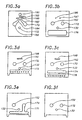
- the exemplary die assembly 100 comprises a plurality of laminated members or plates.
- the plates of FIGS. 3 a-3t are assembled one on top of the other beginning with the plate in FIG. 3a and ending with plate 3t.
- the plates of FIGS. 3f-3k correspond to the plates in FIGS. 4a-4f, respectively, and the plates of FIGS. 3f-3l corresponds to the assembly of FIG. 5, which shows an alternating series of the plurality of first and second orifices 110 and 120 as discussed above.
- the first and second fluids supplied to the die assembly 100 are distributed to the plurality of first and second orifices 110 and 120 as follows.
- the first fluid is supplied from a first restrictor cavity inlet 132 in the plate of FIG. 3f, also shown in FIG. 4a, to a first restrictor cavity 130 in the plate of FIG. 3g, also shown in FIG. 4b, through a plurality of passages 134 in the plate of FIG. 3h, also shown in FIG. 4c, and into first accumulator cavity 140 in the plate of FIG. 3i, also shown in FIG. 4d, where the first fluid is accumulated.
- the first fluid is then supplied from the accumulator cavity 140 through a plurality of passages 136 in the plate of FIG. 3j, also shown in FIG. 4e, to a plurality of first slots 109 in the plate of FIG. 3k, also shown in FIG. 4f.
- the plurality of first slots 109 form the plurality of first orifices 110 shown in FIG. 5 when the plate of FIG. 3k is disposed between the plate of FIG. 3j and the plate of FIG. 31.
- the second fluid is supplied from a second restrictor cavity inlet 152 in the plates of FIGS. 3f-3o to a second restrictor cavity 150 in the plate of FIG. 3o, through a plurality of passages 135 in the plate of FIG. 3n, and into a second accumulator cavity 160 in the plate of FIG. 3m where the second fluid is accumulated.
- the second fluid accumulated in the accumulator cavity 160 is then supplied through a plurality of passages 137 in the plate of FIG. 31 to a plurality of second slots 119 in the plate of FIG. 3k.
- the first fluid mass flow rate through each of the passages 134 is controlled by varying a size of the passages 134.
- the first fluid supplied from the first restrictor cavity 130 is substantially uniformly distributed and supplied to the first accumulator cavity 140 by the plurality passages 134 having varying sizes to compensate for decreasing pressure along portions of the first restrictor cavity outlet and to provide substantially the same first fluid mass flow rate through each of the passages 134.
- the substantially uniformly distributed first fluid is accumulated in the first accumulator cavity 140 and supplied through a plurality of passages 136 at the first accumulator cavity outlet to the plurality of first orifices 110.
- the plurality of first orifices 110 which are substantially the same size, dispense the uniformly distributed first fluid to form the plurality of first fluid flows at the first velocity and at substantially the same mass flow rate.
- the second fluid supplied from the second restrictor cavity 150 is substantially uniformly distributed and supplied to the second accumulator cavity 160 by the plurality of passages 135 having varying sizes to compensate for decreasing pressure along portions of the second restrictor cavity outlet and to provide substantially the same second fluid mass flow rate through each of the passages 135.
- the substantially uniformly distributed second fluid is accumulated in the second accumulator cavity 160 and supplied through a plurality of passages 137 at the second accumulator cavity outlet to the plurality of second orifices 120.
- the plurality of second orifices 120 which are substantially the same size, dispense the uniformly distributed second fluid to form the plurality of second fluid flows at the second velocity and at substantially the same mass flow rate.
- the fluid mass flow rates through any one or more of the orifices 110 and 120 may be selectively varied by varying a size of the corresponding orifices.
- the fluid mass flow rate through any one or more of the first and second orifices 110 and 120 may be selectively varied by varying a pressure across the corresponding orifices.
- the pressure across an orifice may be decreased, for example, by forming an additional cavity, which causes a fluid pressure drop, along the fluid flow path to the selected orifice. If the die assembly is fabricated from a plurality of individual plates as discussed above, the additional cavity or cavities may be formed readily in one of the existing plates or in an additional plate.
- FIG. 5 shows the plurality of second slots 119, which form the plurality of second orifices 120, disposed in a recess with a tapered aperture 121 relative to the plurality of first slots 109, which form the plurality of first orifices 110.
- this configuration reduces the tendency of the first fluid flows to migrate from the plurality of first orifices 110 back upward and into the plurality of second orifices 120 and also modifies the plurality of second fluid flows.
- the plates of FIGS. 3j-31 have corresponding tapered slots 121 to provide the tapered aperture when the plates of FIGS. 3j-31 are assembled.
- the plates of FIGS. 3j-31 may have slot configurations to provide any combination of the first and second orifice configurations discussed above with respect to FIG. 2a.
- the die assembly 100 includes a third means for generating a high pressure zone proximate an output of each of the plurality of first orifices 110 with converging third fluid flows, wherein the high pressure zone blocks residual fluid flow from the corresponding first orifice after terminating a supply of first fluid to the first orifice as discussed above.
- the plurality of second fluid flows are diverted to form the high pressure zones as discussed below.
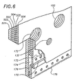
- the die assembly 100 comprises a plurality of laminated members or plates, wherein the plates of FIGS. 3b-3f correspond to plates 502-506 in the partial die assembly of FIG. 6, respectively.
- the third fluid is supplied from a third fluid inlet 172 extending through the plates of FIGS. 3b-3e into a first distribution cavity 170 in the plate of FIG. 3e, through a plurality of orifices 173 in the plate of FIG. 3d, into a cavity 174 in the plate of FIG. 3c, and into a cavity 176 in the plate of FIG. 3b.
- the fourth fluid is then supplied from the cavity 176 through a first plurality of orifices 178 in the plate of FIG. 3c, which orifices 178 form a first component of the converging third fluid flows.
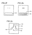
- the third fluid also is supplied from the third fluid inlet 172 which continues to extend through the plates of FIGS. 3e-3q into a second distribution cavity 180 in the plate of FIG. 3q, into a plurality of orifices 183 in the plate of FIG. 3r, into a cavity 184 in the plate of FIG. 3s, and into a cavity 186 in the plate of FIG. 3t.
- the fourth fluid is then supplied from the cavity 186 through a second plurality of orifices 188 in the plate of FIG.
- the converging third fluid flows are dispensed from the respective orifices 178 and 188 at substantially the same mass flow rate.
- the third fluid mass flow rate through any one or more of the orifices 178 and 188 may be selectively varied as discussed above.
- the first component of the converging third fluid flows emanates from the first plurality of orifices 178 and the second component of converging third fluid flows emanates from the second plurality of orifices 188 converge to form a high pressure zone proximate an output of each of the plurality of first orifices 110.
- the converging third fluid flows in this exemplary embodiment do not have a flow component in the flow direction of the first fluid flows, wherein the plurality of high pressure zones are useable to stem or block the flow of residual fluid from the plurality of first fluid orifices after terminating a first fluid supply to the first fluid inlet 132.
- the converging third fluid flows are useable to form separate first fluid flows as discussed above.
- the exemplary embodiments of the die assembly 100 may be formed of a plurality of plates of substantially the same thickness, or alternatively, may be formed of a plurality of plates having different plate thicknesses, wherein each plate thickness is determined by the size of the conduits or cavities defined thereby as shown in FIGS. 3-5.
- the plates may be formed from metals, plastics, and ceramics among other materials, and the plates may be fabricated by stamping, punching, chemical etching, machining, and laser cutting among other processes, which are relatively cost effective alternatives to the prior art.
- a die assembly 100 comprising a plurality of plates, as shown in the exemplary embodiments, provides considerable design flexibility in the configuration of the arrays or orifices, and the fluid flow and the distribution paths, which design and fabrication are not limited by the constraints imposed by prior art drilling processes.
- the plates of the present die assembly may be readily fabricated to produce die assemblies having configurations based on one or more of the exemplary configurations of FIG. 2b.
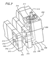
- FIG. 7 is an exemplary die adapter assembly 200 for mounting the die assembly 100 and for supplying fluids thereto.
- the die adapter assembly 200 includes a die assembly mounting interface 210 having a first fluid outlet port 212, a second fluid outlet port 214, and a control or third fluid outlet port 216, which are each coupled by corresponding conduits to corresponding fluid inlets ports 213, 215, and 217 on a body portion 220 of the adapter 200.
- the die adapter assembly 200 includes a second interface 230 with a first fluid outlet port 232, a second fluid outlet port 234, and a control or third fluid outlet port 236, which are also coupled by corresponding conduit extensions, not shown, to corresponding fluid inlets ports 213, 215, and 217 on the body portion 220 of the adapter 200.
- the second mounting interface 230 is oriented at an angle relative to the first mounting interface 210, which in the exemplary embodiment is a 90 degree angle.
- the die assembly 100 is coupled to the adapter 200 by mounting the die assembly 100 on the mounting interface 210 or 230.
- a sealing member like an o-ring, not shown, is disposed in a seat about each of the fluid outlets of the mounting interface 210 and 230 to provide a seal between the die assembly 100 and the adapter 200.
- the die assembly 100 and mounting interfaces 210 and 230 may also include mating alignment tabs to facilitate alignment and mounting of the die assembly 100 on the adapter 200.
- the die assembly 100 is mounted between the adapter interface 210 and a corresponding retaining plate 240, which retains the die assembly 100 mounted on the interface.
- a threaded bolt is disposed through a central bore 232 of the retaining plate 230, and through a central bore of the die assembly 100, and into a threaded bore 222 of the body portion 220 of the adapter assembly 200, which permits ready installation and removal of the die assembly 100 relative to the adapter assembly 200.
- a similar retaining plate is mounted on the unused mounting interface to seal the fluid outlet ports thereon.
- a second die assembly 100 is mounted on the second mounting interface so that the adapter 200 supplies fluids simultaneously to two die assemblies.
- FIG. 3a is a die assembly fluid switching interface plate for diverting a single fluid flow to form either the second fluid flow or the third fluid flow as discussed above.
- the fluid flow switching plate includes a first fluid inlet 132, a switched fluid inlet 190, a primary fluid flow path 192 which couples the fluid inlet 190 with the third fluid inlet 172, and a secondary fluid flow path 194 which couples the fluid inlet 190 with the second fluid inlet 152.
- the primary fluid flow path 192 is a path of least resistance resulting from an asymmetry between the primary path 192 and the secondary path 194 so that fluid supplied to the fluid inlet 190 has a tendency to follow the curved primary fluid flow path 192 toward the third fluid inlet 172.
- the fluid from the fluid inlet 190 is diverted from the primary path 192 to the secondary path 194 by introducing an obstruction along the primary path 192, which causes the fluid to flow along the secondary path 194 toward the second fluid inlet 152.
- the obstruction is a control air flow introduced from a control fluid inlet 193, which urges the switched fluid toward the secondary fluid flow path 194.
- the plate of FIG. 3a also includes a slot 195 with opposing end portions coupled by corresponding ports 196 and 197 in the plate of FIG. 3b to a recess 198 formed in the adjacent plates of FIGS. 3c and 3d for fluid pressure balancing.
- the first fluid outlet 212, the second fluid outlet 214, and the control fluid outlet 216 of the die assembly adapter 200 are coupled, respectively, to the first fluid inlet 132, the switched fluid inlet 190, and the control fluid inlet 193 of the switching plate of FIG. 3a to supply fluid to the die assembly 100.
- the die assembly adapter 200 is coupled to an MR-1300 nozzle module available from ITW Dynatec, Hendersonville, Tennessee, USA which includes a pneumatically actuatable valve for controlling the supply of first fluid to the first fluid inlet 213 of the die assembly adapter 200.
- the control air inlet 215 of the adapter 200 is coupled to the MR-1300 valve actuation air supply to supply control air to the control fluid inlet 193 of the die assembly 100, which directs fluid from the switched fluid inlet 190 to the fluid inlet 152 of the die assembly when the MR-1300 valve is opened to supply first fluid to the first fluid inlet 132 of the die assembly 100.
- the first fluid and the second fluid supplied to the die assembly 100 are dispensed from the first and second orifices 110 and 120 as discussed above. And when the MR-1300 valve is closed to terminate the first fluid supply, control air to the control fluid inlet 193 of the die assembly 100 is terminated, wherein fluid from the switched fluid inlet 190 is directed to the fluid inlet 172 to form the converging air flows, which block first fluid from the first orifices as discussed above.
- FIG. 3z is a die assembly fluid interface plate useable as an alternative to the die assembly fluid switching interface plate in FIG 3a, wherein the fluid inlet 190 of the die assembly 100 is coupled directly to the second fluid inlet 152, and the fluid inlet 193 of the die assembly 100 is coupled directly to the third fluid inlet 172.
- the control air inlet 215 of the adapter 200 is coupled to the MR-1300 valve actuation air supply to supply a control air to the fluid inlet 193 of the die assembly 100 when the MR-1300 valve is closed to terminate first fluid to the first fluid inlet 132 of the die assembly 100.
- This dedicated configuration provides more responsive residual first fluid flow blocking since there is no switching delay required to form the converging third fluid flows.
- the converging third fluid flows of the die assembly thus form high pressure zones in the presence of, but are unaffected by, the second fluid flows, which draw and attenuate the first fluid flows.
- the fluid supplied to the fluid inlet 193 is unrelated to the MR-1300 valve actuation air supply tc provide still more control over the respective fluid flows.
- the meltblowing method and apparatus disclosed herein dispense meltblown adhesives onto substrates in manufacturing processes including the production of bodily fluid absorbing hygienic articles.
- a configuration for these applications which is shown in FIG. 7, a plurality of at least two adjacent die assemblies 100 are disposed in corresponding die assembly adapters 200 arranged side by side to form a linear array of the plurality of corresponding adjacent first and second orifices 110 and 120 of each of the adjacent die assemblies 100.
- the first and second orifices of the die assembly have dimensions between approximately 0.001 and 0.030 inches (0.025 and 0.75 mm) on each side. These dimensions are not limiting however, and may be more or less for these and other applications.
- At least one of the endmost first orifices of the plurality of adjacent die assemblies has a modified first fluid flow vacillation to control the edge profile or edge definition of meltblown adhesive dispensed from the array of die assemblies according to the aspects and embodiments of the invention discussed above.
- the plurality of first orifices of the plurality of adjacent die assemblies are oriented to produce a slightly diverging pluralities of first fluid flows, which provide a uniform meltblown adhesive application onto the substrates.
- at least one or more of the plurality of first fluid flows are at different mass flow rates according to one or more configurations discussed above.
- the plates of the die assembly 100 may be assembled by soldering, brazing, mechanical clamping, fusion under high temperture and pressure, and adhesive bonding among other means.
Landscapes
- Engineering & Computer Science (AREA)
- Textile Engineering (AREA)
- Mechanical Engineering (AREA)
- Manufacturing & Machinery (AREA)
- Spinning Methods And Devices For Manufacturing Artificial Fibers (AREA)
- Nonwoven Fabrics (AREA)
- Absorbent Articles And Supports Therefor (AREA)
Claims (18)
- Appareil de fusion-soufflage ayant un premier orifice de fluide (12) dans un élément corps (10),
deux deuxièmes orifices de fluide (14) dans l'élément corps (10) qui flanquent le premier orifice de fluide (12) sur des côtés sensiblement opposés de celui-ci,
le premier orifice de fluide (12) faisant saillie par rapport aux deux deuxièmes orifices de fluide (14),
le premier orifice de fluide (12) et les deuxièmes orifices de fluide (14) ayant chacun un conduit de fluide correspondant situé dans l'élément corps (10), et
dans lequel un filament (FF) émane du premier orifice de fluide (12),
caractérisé par le fait qu'il est prévu des moyens destinés à faire vaciller le filament (FF) sensiblement dans un plan entre les deux deuxièmes orifices de fluide (14) sur des côtés sensiblement opposés du premier orifice de fluide (12). - Appareil selon la revendication 1, comprenant en outre un ensemble de premiers orifices de fluide (12) dans l'élément corps (10) et un ensemble de deuxièmes orifices de fluide (14) dans l'élément corps (10), chaque premier orifice de fluide (12) étant flanqué, sur des côtés sensiblement opposés, de deux deuxièmes orifices de fluide séparés (14), l'ensemble de premiers orifices de fluide (12) et l'ensemble de deuxièmes orifices de fluide (14) ayant chacun des conduits de fluide correspondants situés dans l'élément corps (10).
- Appareil selon la revendication 2, dans lequel un filament (FF) émane de chacun de l'ensemble de premiers orifices de fluide (12), les filaments (FF) vacillant chacun sensiblement dans un plan entre les deux deuxièmes orifices de fluide (14) sur des côtés sensiblement opposés du premier orifice de fluide (12) correspondant.
- Appareil selon la revendication 3, dans lequel l'ensemble de premiers orifices de fluide (12) et l'ensemble de deuxièmes orifices de fluide (14) sont alignés en une série.
- Appareil selon l'une des revendications 1 à 3, dans lequel les conduits du premier orifice de fluide (12) et des deuxièmes orifices de fluide (14) sont disposés de manière non convergente dans l'élément corps (10).
- Appareil selon l'une des revendications 1 à 3, dans lequel les conduits du premier orifice de fluide (12) et des deuxièmes orifices de fluide (14) sont disposés en parallèle dans l'élément corps (10).
- Appareil selon l'une des revendications 1, 2, 5 et 6, dans lequel à chaque premier orifice de fluide (12) ne sont pas associés plus de deux deuxièmes orifices de fluide (14).
- Appareil selon l'une des revendications 1 à 3, comprenant en outre un substrat mobile ayant chaque premier orifice de fluide (12) et les deux deuxièmes orifices de fluide (14) disposés sur des côtés opposés de celui-ci et alignés non parallèlement à une direction du substrat mobile.
- Appareil selon l'une des revendications 2, 3, 4 et 8, dans lequel l'ensemble de premiers orifices de fluide (12) fait saillie par rapport à l'ensemble de deuxièmes orifices de fluide (14).
- Appareil selon l'une des revendications 1 à 9, dans lequel l'élément corps (10) comprend un ensemble d'au moins deux plaques (501-506).
- Appareil selon la revendication 10, dans lequel l'élément corps (10) comprend un ensemble de plaques parallèles (501-506).
- Procédé de fusion-soufflage comprenant la formation d'un filament (FF) par étirage d'un premier courant de fluide (F1) par deux deuxièmes courants de fluide séparés (F2) dirigés le long de côtés sensiblement opposés du premier courant de fluide (F1),
caractérisé par le fait qu'on fait vaciller le filament (FF) sensiblement dans un plan entre les deux deuxièmes courants de fluide (F2) le long de côtés sensiblement opposés de celui-ci. - Procédé selon la revendication 12, comprenant en outre la formation d'un ensemble de filaments (FF) par étirage d'un ensemble correspondant de premiers courants de fluide (F1) chacun par deux deuxièmes courants de fluide séparés (F2) correspondants dirigés le long de côtés sensiblement opposés du premier courant de fluide (F1) correspondant, et
la production de vacillement de chacun des filaments (FF) sensiblement dans un plan entre les deux deuxièmes courants de fluide (F2) correspondants le long de côtés sensiblement opposés de celui-ci. - Procédé selon l'une des revendications 12 et 13, comprenant en outre la formation de chaque premier courant de fluide (F1) avec un premier fluide émis d'un premier orifice (12) correspondant situé dans un élément corps (10), la formation de chaque deuxième courant de fluide (F2) avec un deuxième fluide émis d'un deuxième orifice (14) correspondant situé dans l'élément corps (10), chaque premier orifice (12) étant flanqué, sur des côtés sensiblement opposés, de deux deuxièmes orifices de fluide séparés (14), et chaque premier orifice (12) faisant saillie par rapport aux deux deuxièmes orifices (14) correspondants.
- Procédé selon l'une des revendications 12, 13 et 14, comprenant en outre le dépôt de chaque filament (FF) sur un substrat se déplaçant sensiblement non parallèlement au plan de vacillement de celui-ci.
- Procédé selon l'une des revendications 13 et 14, comprenant en outre la production de vacillement de l'ensemble des filaments (FF) côte à côte dans des plans sensiblement non parallèles à une direction d'un substrat mobile, et le dépôt des filaments (FF) sur le substrat mobile.
- Procédé selon l'une des revendications 12, 13 et 14, comprenant en outre le fait de diriger le premier courant de fluide (F1) et les deuxièmes courants de fluide (F2) de manière non convergente.
- Procédé selon l'une des revendications 12, 13 et 14, comprenant en outre le fait de diriger le premier courant de fluide (F1) et les deuxièmes courants de fluide (F2) en parallèle.
Applications Claiming Priority (2)
| Application Number | Priority Date | Filing Date | Title |
|---|---|---|---|
| US08/717,080 US5902540A (en) | 1996-10-08 | 1996-10-08 | Meltblowing method and apparatus |
| US717080 | 1996-10-18 |
Publications (2)
| Publication Number | Publication Date |
|---|---|
| EP0835952A1 EP0835952A1 (fr) | 1998-04-15 |
| EP0835952B1 true EP0835952B1 (fr) | 2003-02-05 |
Family
ID=24880635
Family Applications (1)
| Application Number | Title | Priority Date | Filing Date |
|---|---|---|---|
| EP97307932A Expired - Lifetime EP0835952B1 (fr) | 1996-10-08 | 1997-10-07 | Dispositif et procédé pour fusion-soufflage |
Country Status (10)
| Country | Link |
|---|---|
| US (3) | US5902540A (fr) |
| EP (1) | EP0835952B1 (fr) |
| JP (2) | JP4008547B2 (fr) |
| KR (1) | KR100239833B1 (fr) |
| CN (1) | CN1088767C (fr) |
| AU (1) | AU699826B2 (fr) |
| BR (1) | BR9704982A (fr) |
| CA (1) | CA2217684C (fr) |
| DE (1) | DE69718870T2 (fr) |
| TW (1) | TW353635B (fr) |
Cited By (5)
| Publication number | Priority date | Publication date | Assignee | Title |
|---|---|---|---|---|
| USD588617S1 (en) | 2008-04-14 | 2009-03-17 | Nordson Corporation | Nozzle assembly |
| US7798434B2 (en) | 2006-12-13 | 2010-09-21 | Nordson Corporation | Multi-plate nozzle and method for dispensing random pattern of adhesive filaments |
| US8074902B2 (en) | 2008-04-14 | 2011-12-13 | Nordson Corporation | Nozzle and method for dispensing random pattern of adhesive filaments |
| US10213805B2 (en) | 2009-07-29 | 2019-02-26 | Illinois Tool Works Inc. | Wide pattern nozzle |
| US12226792B2 (en) | 2019-03-11 | 2025-02-18 | Illinois Tool Works Inc. | Nozzle arrangement for applying fluids, and method for producing a main body of such a nozzle arrangement |
Families Citing this family (158)
| Publication number | Priority date | Publication date | Assignee | Title |
|---|---|---|---|---|
| US5902540A (en) | 1996-10-08 | 1999-05-11 | Illinois Tool Works Inc. | Meltblowing method and apparatus |
| US6680021B1 (en) | 1996-07-16 | 2004-01-20 | Illinois Toolworks Inc. | Meltblowing method and system |
| US6422848B1 (en) | 1997-03-19 | 2002-07-23 | Nordson Corporation | Modular meltblowing die |
| US5882573A (en) | 1997-09-29 | 1999-03-16 | Illinois Tool Works Inc. | Adhesive dispensing nozzles for producing partial spray patterns and method therefor |
| US6077375A (en) * | 1998-04-15 | 2000-06-20 | Illinois Tool Works Inc. | Elastic strand coating process |
| US6540831B1 (en) | 1998-04-17 | 2003-04-01 | Nordson Corporation | Method and apparatus for applying a controlled pattern of fibrous material to a moving substrate |
| US6248097B1 (en) | 1998-08-06 | 2001-06-19 | Kimberly-Clark Worldwide, Inc. | Absorbent article with more conformable elastics |
| US6652693B2 (en) * | 1998-08-06 | 2003-11-25 | Kimberly-Clark Worldwide, Inc. | Process for applying adhesive in an article having a strand material |
| US6235137B1 (en) | 1998-08-06 | 2001-05-22 | Kimberly-Clark Worldwide, Inc. | Process for manufacturing an elastic article |
| US6051180A (en) * | 1998-08-13 | 2000-04-18 | Illinois Tool Works Inc. | Extruding nozzle for producing non-wovens and method therefor |
| US6200635B1 (en) | 1998-08-31 | 2001-03-13 | Illinois Tool Works Inc. | Omega spray pattern and method therefor |
| US6602554B1 (en) * | 2000-01-14 | 2003-08-05 | Illinois Tool Works Inc. | Liquid atomization method and system |
| JP4474620B2 (ja) * | 2000-03-14 | 2010-06-09 | ノードソン株式会社 | 糸状又は紐状物体に接着剤を塗布する装置と方法 |
| US6719846B2 (en) | 2000-03-14 | 2004-04-13 | Nordson Corporation | Device and method for applying adhesive filaments to materials such as strands or flat substrates |
| US6361634B1 (en) | 2000-04-05 | 2002-03-26 | Kimberly-Clark Worldwide, Inc. | Multiple stage coating of elastic strands with adhesive |
| US8182457B2 (en) | 2000-05-15 | 2012-05-22 | Kimberly-Clark Worldwide, Inc. | Garment having an apparent elastic band |
| US6435425B1 (en) | 2000-05-15 | 2002-08-20 | Nordson Corporation | Module and nozzle for dispensing controlled patterns of liquid material |
| US6572033B1 (en) | 2000-05-15 | 2003-06-03 | Nordson Corporation | Module for dispensing controlled patterns of liquid material and a nozzle having an asymmetric liquid discharge orifice |
| US6833179B2 (en) | 2000-05-15 | 2004-12-21 | Kimberly-Clark Worldwide, Inc. | Targeted elastic laminate having zones of different basis weights |
| US6969441B2 (en) | 2000-05-15 | 2005-11-29 | Kimberly-Clark Worldwide, Inc. | Method and apparatus for producing laminated articles |
| US6375099B1 (en) | 2000-06-21 | 2002-04-23 | Illinois Tool Works Inc. | Split output adhesive nozzle assembly |
| US6520237B1 (en) * | 2000-07-24 | 2003-02-18 | Illinois Tool Works Inc | Variable spacing strand coating system and method |
| AU2001282537A1 (en) * | 2000-08-31 | 2002-03-13 | Japan Tobacco Inc. | Filter manufacturing machine |
| US20030131791A1 (en) * | 2000-11-21 | 2003-07-17 | Schultz Carl L. | Multiple orifice applicator system and method of using same |
| US6733831B2 (en) | 2001-10-30 | 2004-05-11 | Nordson Corporation | Method and apparatus for use in coating elongated bands |
| US6601741B2 (en) | 2001-11-28 | 2003-08-05 | Illinois Tool Works Inc. | Laminated distribution manifold plate system |
| US6939334B2 (en) | 2001-12-19 | 2005-09-06 | Kimberly-Clark Worldwide, Inc. | Three dimensional profiling of an elastic hot melt pressure sensitive adhesive to provide areas of differential tension |
| US6805965B2 (en) | 2001-12-21 | 2004-10-19 | Kimberly-Clark Worldwide, Inc. | Method for the application of hydrophobic chemicals to tissue webs |
| US6716309B2 (en) | 2001-12-21 | 2004-04-06 | Kimberly-Clark Worldwide, Inc. | Method for the application of viscous compositions to the surface of a paper web and products made therefrom |
| US6902796B2 (en) | 2001-12-28 | 2005-06-07 | Kimberly-Clark Worldwide, Inc. | Elastic strand bonded laminate |
| US20030173024A1 (en) * | 2002-03-15 | 2003-09-18 | Nordson Corporation | Method of securing elastic strands to flat substrates and products produced by the method |
| US20050013975A1 (en) * | 2003-07-14 | 2005-01-20 | Nordson Corporation | Method of securing elastic strands to flat substrates and products produced by the method |
| US6936125B2 (en) * | 2002-03-15 | 2005-08-30 | Nordson Corporation | Method of applying a continuous adhesive filament to an elastic strand with discrete bond points and articles manufactured by the method |
| WO2003086949A2 (fr) * | 2002-04-12 | 2003-10-23 | Nordson Corporation | Applicateur et buse permettant de distribuer des motifs controles de materiau liquide |
| US6911232B2 (en) * | 2002-04-12 | 2005-06-28 | Nordson Corporation | Module, nozzle and method for dispensing controlled patterns of liquid material |
| US8012495B2 (en) * | 2002-05-07 | 2011-09-06 | Georgia-Pacific Consumer Products Lp | Lotion-treated tissue and towel |
| US7169400B2 (en) * | 2002-05-07 | 2007-01-30 | Fort James Corporation | Waterless lotion and lotion-treated substrate |
| US7335273B2 (en) | 2002-12-26 | 2008-02-26 | Kimberly-Clark Worldwide, Inc. | Method of making strand-reinforced elastomeric composites |
| US7015155B2 (en) | 2002-07-02 | 2006-03-21 | Kimberly-Clark Worldwide, Inc. | Elastomeric adhesive |
| US7316840B2 (en) | 2002-07-02 | 2008-01-08 | Kimberly-Clark Worldwide, Inc. | Strand-reinforced composite material |
| US6978486B2 (en) | 2002-07-02 | 2005-12-27 | Kimberly-Clark Worldwide, Inc. | Garment including an elastomeric composite laminate |
| US7316842B2 (en) | 2002-07-02 | 2008-01-08 | Kimberly-Clark Worldwide, Inc. | High-viscosity elastomeric adhesive composition |
| US6977026B2 (en) * | 2002-10-16 | 2005-12-20 | Kimberly-Clark Worldwide, Inc. | Method for applying softening compositions to a tissue product |
| EP1410900A1 (fr) * | 2002-10-17 | 2004-04-21 | Reifenhäuser GmbH & Co. Maschinenfabrik | Procédé de fabrication d'une bande stratifiée |
| US6761800B2 (en) * | 2002-10-28 | 2004-07-13 | Kimberly-Clark Worldwide, Inc. | Process for applying a liquid additive to both sides of a tissue web |
| US20040081794A1 (en) * | 2002-10-29 | 2004-04-29 | Titone David M. | Method for applying adhesive filaments to multiple strands of material and articles formed with the method |
| US7029756B2 (en) | 2002-11-06 | 2006-04-18 | Kimberly-Clark Worldwide, Inc. | Soft tissue hydrophilic tissue products containing polysiloxane and having unique absorbent properties |
| US6964725B2 (en) * | 2002-11-06 | 2005-11-15 | Kimberly-Clark Worldwide, Inc. | Soft tissue products containing selectively treated fibers |
| US6949168B2 (en) * | 2002-11-27 | 2005-09-27 | Kimberly-Clark Worldwide, Inc. | Soft paper product including beneficial agents |
| US7601218B2 (en) * | 2002-12-05 | 2009-10-13 | Valco Cincinnati, Inc. | Auto-tracking dispenser |
| ES2264289B1 (es) * | 2003-01-17 | 2007-12-01 | Universidad De Sevilla | Nuevo metodo de generacion de micro-corrientes fluidas para la produccion de micro-burbujas, micro-espumas, micro-gotas, micro-emulsiones, y micro-capsulas. |
| US7578882B2 (en) * | 2003-01-22 | 2009-08-25 | Nordson Corporation | Module, nozzle and method for dispensing controlled patterns of liquid material |
| US7462240B2 (en) * | 2003-01-24 | 2008-12-09 | Nordson Corporation | Module, nozzle and method for dispensing controlled patterns of liquid material |
| US7018188B2 (en) * | 2003-04-08 | 2006-03-28 | The Procter & Gamble Company | Apparatus for forming fibers |
| US7396593B2 (en) * | 2003-05-19 | 2008-07-08 | Kimberly-Clark Worldwide, Inc. | Single ply tissue products surface treated with a softening agent |
| US7041171B2 (en) * | 2003-09-10 | 2006-05-09 | Kastalon, Inc. | Nozzle for use in rotational casting apparatus |
| US6989061B2 (en) * | 2003-08-22 | 2006-01-24 | Kastalon, Inc. | Nozzle for use in rotational casting apparatus |
| US7270711B2 (en) * | 2004-06-07 | 2007-09-18 | Kastalon, Inc. | Nozzle for use in rotational casting apparatus |
| US7168932B2 (en) * | 2003-12-22 | 2007-01-30 | Kimberly-Clark Worldwide, Inc. | Apparatus for nonwoven fibrous web |
| US6972104B2 (en) * | 2003-12-23 | 2005-12-06 | Kimberly-Clark Worldwide, Inc. | Meltblown die having a reduced size |
| US7470345B2 (en) * | 2003-12-30 | 2008-12-30 | Kimberly-Clark Worldwide, Inc. | Rolled paper product having high bulk and softness |
| US7601657B2 (en) | 2003-12-31 | 2009-10-13 | Kimberly-Clark Worldwide, Inc. | Single sided stretch bonded laminates, and methods of making same |
| US20050233667A1 (en) * | 2004-04-16 | 2005-10-20 | Tamko Roofing Products, Inc. | System and method for manufacturing polymer mat with reduced capacity spinning pumps |
| US7067009B2 (en) * | 2004-06-09 | 2006-06-27 | Illinois Tool Works Inc. | Strand guide implements or mechanisms for use in connection with material dispensing and coating nozzles |
| US7316552B2 (en) | 2004-12-23 | 2008-01-08 | Kimberly-Clark Worldwide, Inc. | Low turbulence die assembly for meltblowing apparatus |
| US7465367B2 (en) * | 2005-01-07 | 2008-12-16 | Innovative Elastics Limited | Process for forming a laminate |
| US7906722B2 (en) | 2005-04-19 | 2011-03-15 | Palo Alto Research Center Incorporated | Concentrating solar collector with solid optical element |
| CN100518950C (zh) * | 2005-06-14 | 2009-07-29 | 侯红蕾 | 热熔胶可控喷丝方法及装置 |
| US20070102841A1 (en) * | 2005-11-04 | 2007-05-10 | Nordson Corporation | Applicators and methods for dispensing a liquid material |
| US20070169806A1 (en) * | 2006-01-20 | 2007-07-26 | Palo Alto Research Center Incorporated | Solar cell production using non-contact patterning and direct-write metallization |
| US7799371B2 (en) * | 2005-11-17 | 2010-09-21 | Palo Alto Research Center Incorporated | Extruding/dispensing multiple materials to form high-aspect ratio extruded structures |
| US20070107773A1 (en) * | 2005-11-17 | 2007-05-17 | Palo Alto Research Center Incorporated | Bifacial cell with extruded gridline metallization |
| US7765949B2 (en) * | 2005-11-17 | 2010-08-03 | Palo Alto Research Center Incorporated | Extrusion/dispensing systems and methods |
| US20070125886A1 (en) * | 2005-12-01 | 2007-06-07 | 3M Innovative Properties Company | Methods of spraying multi-component liquids |
| WO2007064625A1 (fr) * | 2005-12-01 | 2007-06-07 | 3M Innovative Properties Company | Systèmes de pulvérisation de liquide à composants multiples |
| EP1954399A4 (fr) * | 2005-12-01 | 2008-11-26 | 3M Innovative Properties Co | Systèmes de pulvérisation de liquide à composants multiples |
| US8388992B2 (en) | 2006-03-28 | 2013-03-05 | Georgia-Pacific Consumer Products Lp | Anti-microbial hand towel with time-delay chromatic transfer indicator and absorbency rate delay |
| US7851693B2 (en) | 2006-05-05 | 2010-12-14 | Palo Alto Research Center Incorporated | Passively cooled solar concentrating photovoltaic device |
| US20080008865A1 (en) * | 2006-06-23 | 2008-01-10 | Georgia-Pacific Consumer Products Lp | Antimicrobial hand towel for touchless automatic dispensers |
| US7807591B2 (en) * | 2006-07-31 | 2010-10-05 | 3M Innovative Properties Company | Fibrous web comprising microfibers dispersed among bonded meltspun fibers |
| US7858163B2 (en) * | 2006-07-31 | 2010-12-28 | 3M Innovative Properties Company | Molded monocomponent monolayer respirator with bimodal monolayer monocomponent media |
| US7905973B2 (en) * | 2006-07-31 | 2011-03-15 | 3M Innovative Properties Company | Molded monocomponent monolayer respirator |
| US9770058B2 (en) | 2006-07-17 | 2017-09-26 | 3M Innovative Properties Company | Flat-fold respirator with monocomponent filtration/stiffening monolayer |
| US7902096B2 (en) * | 2006-07-31 | 2011-03-08 | 3M Innovative Properties Company | Monocomponent monolayer meltblown web and meltblowing apparatus |
| US7947142B2 (en) * | 2006-07-31 | 2011-05-24 | 3M Innovative Properties Company | Pleated filter with monolayer monocomponent meltspun media |
| US8029723B2 (en) * | 2006-07-31 | 2011-10-04 | 3M Innovative Properties Company | Method for making shaped filtration articles |
| EP2049720B1 (fr) | 2006-07-31 | 2013-09-04 | 3M Innovative Properties Company | Procédé de fabrication d'articles filtrants profilés |
| US7754041B2 (en) * | 2006-07-31 | 2010-07-13 | 3M Innovative Properties Company | Pleated filter with bimodal monolayer monocomponent media |
| US20100019058A1 (en) * | 2006-09-13 | 2010-01-28 | Vanderzwet Daniel P | Nozzle assembly for cold gas dynamic spray system |
| US8226391B2 (en) * | 2006-11-01 | 2012-07-24 | Solarworld Innovations Gmbh | Micro-extrusion printhead nozzle with tapered cross-section |
| US7922471B2 (en) * | 2006-11-01 | 2011-04-12 | Palo Alto Research Center Incorporated | Extruded structure with equilibrium shape |
| US7780812B2 (en) * | 2006-11-01 | 2010-08-24 | Palo Alto Research Center Incorporated | Extrusion head with planarized edge surface |
| US8322025B2 (en) * | 2006-11-01 | 2012-12-04 | Solarworld Innovations Gmbh | Apparatus for forming a plurality of high-aspect ratio gridline structures |
| US7928015B2 (en) | 2006-12-12 | 2011-04-19 | Palo Alto Research Center Incorporated | Solar cell fabrication using extruded dopant-bearing materials |
| US7638438B2 (en) * | 2006-12-12 | 2009-12-29 | Palo Alto Research Center Incorporated | Solar cell fabrication using extrusion mask |
| USD550261S1 (en) | 2006-12-13 | 2007-09-04 | Nordson Corporation | Adhesive dispensing nozzle |
| US8177938B2 (en) | 2007-01-19 | 2012-05-15 | Georgia-Pacific Consumer Products Lp | Method of making regenerated cellulose microfibers and absorbent products incorporating same |
| WO2008093108A1 (fr) * | 2007-02-02 | 2008-08-07 | G24 Innovations Limited | Transport d'une toile |
| US20080185039A1 (en) * | 2007-02-02 | 2008-08-07 | Hing Wah Chan | Conductor fabrication for optical element |
| US7954449B2 (en) | 2007-05-08 | 2011-06-07 | Palo Alto Research Center Incorporated | Wiring-free, plumbing-free, cooled, vacuum chuck |
| US8033243B2 (en) * | 2007-06-29 | 2011-10-11 | Illinois Tool Works Inc. | Strand positioning guide having reversely oriented V-shaped slots for use in connection with strand coating applicators |
| US8093532B2 (en) * | 2008-03-31 | 2012-01-10 | Electro Scientific Industries, Inc. | Laser machining of fired ceramic and other hard and/or thick materials |
| JP4994312B2 (ja) * | 2008-06-12 | 2012-08-08 | 日本バイリーン株式会社 | 紡糸装置及び不織布製造装置 |
| KR101593022B1 (ko) * | 2008-05-28 | 2016-02-11 | 니혼바이린 가부시기가이샤 | 방사 장치, 부직포 제조 장치 및 부직포의 제조 방법 |
| US7999175B2 (en) * | 2008-09-09 | 2011-08-16 | Palo Alto Research Center Incorporated | Interdigitated back contact silicon solar cells with laser ablated grooves |
| CA2735867C (fr) | 2008-09-16 | 2017-12-05 | Dixie Consumer Products Llc | Feuille de base d'emballage alimentaire a microfibre de cellulose regeneree |
| US20100221435A1 (en) * | 2008-11-07 | 2010-09-02 | Palo Alto Research Center Incorporated | Micro-Extrusion System With Airjet Assisted Bead Deflection |
| US20100117254A1 (en) * | 2008-11-07 | 2010-05-13 | Palo Alto Research Center Incorporated | Micro-Extrusion System With Airjet Assisted Bead Deflection |
| US8704086B2 (en) * | 2008-11-07 | 2014-04-22 | Solarworld Innovations Gmbh | Solar cell with structured gridline endpoints vertices |
| US20100118081A1 (en) * | 2008-11-07 | 2010-05-13 | Palo Alto Research Center Incorporated | Dead Volume Removal From An Extrusion Printhead |
| US8117983B2 (en) * | 2008-11-07 | 2012-02-21 | Solarworld Innovations Gmbh | Directional extruded bead control |
| US8080729B2 (en) * | 2008-11-24 | 2011-12-20 | Palo Alto Research Center Incorporated | Melt planarization of solar cell bus bars |
| US20100130014A1 (en) * | 2008-11-26 | 2010-05-27 | Palo Alto Research Center Incorporated | Texturing multicrystalline silicon |
| US20100139754A1 (en) * | 2008-12-09 | 2010-06-10 | Palo Alto Research Center Incorporated | Solar Cell With Co-Planar Backside Metallization |
| US8960120B2 (en) * | 2008-12-09 | 2015-02-24 | Palo Alto Research Center Incorporated | Micro-extrusion printhead with nozzle valves |
| US20100139756A1 (en) * | 2008-12-10 | 2010-06-10 | Palo Alto Research Center Incorporated | Simultaneously Writing Bus Bars And Gridlines For Solar Cell |
| US20100206356A1 (en) * | 2009-02-18 | 2010-08-19 | Palo Alto Research Center Incorporated | Rotational Trough Reflector Array For Solar-Electricity Generation |
| US20100206302A1 (en) * | 2009-02-18 | 2010-08-19 | Palo Alto Research Center Incorporated | Rotational Trough Reflector Array For Solar-Electricity Generation |
| US20100224123A1 (en) * | 2009-03-09 | 2010-09-09 | Illinois Tool Works Inc. | Modular nozzle unit for web moistening |
| US9186881B2 (en) * | 2009-03-09 | 2015-11-17 | Illinois Tool Works Inc. | Thermally isolated liquid supply for web moistening |
| US20100224703A1 (en) * | 2009-03-09 | 2010-09-09 | Illinois Tool Works Inc. | Pneumatic Atomization Nozzle for Web Moistening |
| US20100224122A1 (en) * | 2009-03-09 | 2010-09-09 | Illinois Tool Works Inc. | Low pressure regulation for web moistening systems |
| US8551562B2 (en) | 2009-07-17 | 2013-10-08 | Illnois Tool Works Inc. | Method for metering hot melt adhesives with variable adhesive volumes |
| CA2771144C (fr) * | 2009-08-14 | 2017-03-07 | The Procter & Gamble Company | Ensemble filiere de filature et procede de formation de fibres au moyen de cet ensemble |
| US9718081B2 (en) * | 2009-08-31 | 2017-08-01 | Illinois Tool Works Inc. | Metering system for simultaneously dispensing two different adhesives from a single metering device or applicator onto a common substrate |
| US9573159B2 (en) * | 2009-08-31 | 2017-02-21 | Illinois Tool Works, Inc. | Metering system for simultaneously dispensing two different adhesives from a single metering device or applicator onto a common substrate |
| WO2011028661A2 (fr) | 2009-09-01 | 2011-03-10 | 3M Innovative Properties Company | Appareil, système et procédé pour former des nanofibres et films de nanofibres |
| CN105399971B (zh) * | 2010-03-25 | 2019-03-01 | 3M创新有限公司 | 复合层 |
| US8586129B2 (en) | 2010-09-01 | 2013-11-19 | Solarworld Innovations Gmbh | Solar cell with structured gridline endpoints and vertices |
| US9827711B2 (en) | 2011-04-21 | 2017-11-28 | Pregis Innovative Packaging Llc | Edge attached film-foam sheet |
| EP2750856A2 (fr) * | 2011-09-02 | 2014-07-09 | 3M Innovative Properties Company | Fils de base, nappes de filets, filières et leurs procédés de production |
| US8985485B2 (en) * | 2011-10-03 | 2015-03-24 | Illinois Tool Works Inc. | Quasi melt blow down system |
| US10371468B2 (en) | 2011-11-30 | 2019-08-06 | Palo Alto Research Center Incorporated | Co-extruded microchannel heat pipes |
| US9120190B2 (en) | 2011-11-30 | 2015-09-01 | Palo Alto Research Center Incorporated | Co-extruded microchannel heat pipes |
| US8875653B2 (en) * | 2012-02-10 | 2014-11-04 | Palo Alto Research Center Incorporated | Micro-extrusion printhead with offset orifices for generating gridlines on non-square substrates |
| US9682392B2 (en) | 2012-04-11 | 2017-06-20 | Nordson Corporation | Method for applying varying amounts or types of adhesive on an elastic strand |
| CN102787374B (zh) * | 2012-07-20 | 2015-02-25 | 东华大学 | 一种制备超细纤维的熔喷模头 |
| US9480996B2 (en) | 2012-09-18 | 2016-11-01 | Ilinois Tool Works Inc. | Fluid dispensing system with nozzle heater |
| CN103966674B (zh) * | 2013-02-01 | 2017-04-12 | 郑州佳研磨具有限公司 | 用于生产不织物基体的喷丝板及其冷却成型装置 |
| US9827579B2 (en) | 2013-03-07 | 2017-11-28 | Sun Tool Corporation | Hot melt adhesive application method and hot melt adhesive application device |
| US9283579B2 (en) | 2013-03-12 | 2016-03-15 | Illinois Tool Works Inc. | Variable volume hot melt adhesive dispensing nozzle or die assembly with choke suppression |
| WO2015126761A1 (fr) | 2014-02-24 | 2015-08-27 | Nanofiber, Inc. | Procédé, appareil et filière de fusion-soufflage |
| MX2016013836A (es) | 2014-04-25 | 2017-03-09 | Firestone Building Prod Co Llc | Materiales de construccion que incluyen una capa de tela no tejida de adhesivo sensible a la presion. |
| US9561654B2 (en) | 2014-11-26 | 2017-02-07 | Illinois Tool Works Inc. | Laminated nozzle with thick plate |
| US9849480B2 (en) | 2014-11-26 | 2017-12-26 | Illinois Tool Works Inc. | Laminated nozzle with thick plate |
| KR101670382B1 (ko) * | 2015-03-10 | 2016-10-28 | 우범제 | 퍼지가스 분사 플레이트 및 그 제조 방법 |
| JP6600981B2 (ja) * | 2015-05-01 | 2019-11-06 | 日本ノズル株式会社 | 不織布製造装置 |
| US10130972B2 (en) * | 2015-09-09 | 2018-11-20 | Illinois Tool Works Inc. | High speed intermittent barrier nozzle |
| CN107775942A (zh) * | 2016-08-31 | 2018-03-09 | 岱纳包装(天津)有限公司 | 一种基于3d扫描的挤出胶胚自动调整和控制挤出吹塑的方法 |
| CN107775946A (zh) * | 2016-08-31 | 2018-03-09 | 岱纳包装(天津)有限公司 | 一种人机交互智能闭环控制全自动吹塑生产线及工艺 |
| US11267595B2 (en) | 2016-11-01 | 2022-03-08 | Pregis Innovative Packaging Llc | Automated furniture bagger and material therefor |
| US11447893B2 (en) | 2017-11-22 | 2022-09-20 | Extrusion Group, LLC | Meltblown die tip assembly and method |
| WO2019168875A1 (fr) | 2018-02-28 | 2019-09-06 | Illinois Tool Works Inc. | Buse d'évacuation d'un ou plusieurs liquides |
| CN108456940B (zh) * | 2018-05-02 | 2020-10-23 | 嘉兴学院 | 一种具有非对称模头的纤维制备装置 |
| DE102019106146A1 (de) * | 2019-03-11 | 2020-09-17 | Illinois Tool Works Inc. | Düsenanordnung zum auftragen von fluiden, system mit einer solchen düsenanordnung und verfahren zum auftragen von fluiden |
| US12173200B2 (en) | 2019-04-04 | 2024-12-24 | Avery Dennison Corporation | Reinforced label assembly |
| JP7593741B2 (ja) * | 2020-03-26 | 2024-12-03 | ノードソン コーポレーション | ノズル、接着剤塗布ヘッド、接着剤塗布装置及びおむつ製造方法 |
| CN119877126B (zh) * | 2025-03-31 | 2025-06-20 | 东华大学 | 一种熔喷纺丝模头与用其制备的中空卷曲纤维基絮片及制备方法 |
Citations (1)
| Publication number | Priority date | Publication date | Assignee | Title |
|---|---|---|---|---|
| US4785996A (en) * | 1987-04-23 | 1988-11-22 | Nordson Corporation | Adhesive spray gun and nozzle attachment |
Family Cites Families (131)
| Publication number | Priority date | Publication date | Assignee | Title |
|---|---|---|---|---|
| US33481A (en) * | 1861-10-15 | Improvement in metallic cartridges | ||
| US33448A (en) * | 1861-10-08 | Improvement in apparatus for tanning | ||
| US33159A (en) * | 1861-08-27 | Improved amalgamator | ||
| US33158A (en) * | 1861-08-27 | Improvement in harvesting-machines | ||
| US33605A (en) * | 1861-10-29 | Improvement in modes of watering cattle on railroad-cars | ||
| US2031387A (en) * | 1934-08-22 | 1936-02-18 | Schwarz Arthur | Nozzle |
| US2212448A (en) * | 1935-06-08 | 1940-08-20 | Owens Corning Fiberglass Corp | Method and apparatus for the production of fibers from molten glass and similar meltable materials |
| US2297726A (en) * | 1938-04-02 | 1942-10-06 | Thermo Plastics Corp | Method and apparatus for drying or the like |
| BE492010A (fr) | 1948-11-05 | |||
| US2628386A (en) * | 1952-04-29 | 1953-02-17 | Modern Plastic Machinery Corp | Web extrusion die |
| US3038202A (en) * | 1959-01-28 | 1962-06-12 | Multiple Extrusions Inc | Method and apparatus for making multiple tube structures by extrusion |
| DE1132896B (de) * | 1961-01-05 | 1962-07-12 | Bayer Ag | Verfahren zur Herstellung von koernigen oder zylinderfoermigen Granulaten |
| US3178770A (en) * | 1962-01-19 | 1965-04-20 | Du Pont | Variable orifice extruder die |
| NL125332C (fr) * | 1962-06-25 | |||
| US3192563A (en) * | 1962-06-25 | 1965-07-06 | Monsanto Co | Laminated spinneret |
| US3176345A (en) * | 1962-06-25 | 1965-04-06 | Monsanto Co | Spinnerette |
| US3204290A (en) * | 1962-12-27 | 1965-09-07 | Monsanto Co | Laminated spinneret |
| US3501805A (en) * | 1963-01-03 | 1970-03-24 | American Cyanamid Co | Apparatus for forming multicomponent fibers |
| US3253301A (en) * | 1963-01-14 | 1966-05-31 | Monsanto Co | Non-circular spinneret orifices |
| DE1584324A1 (de) * | 1965-04-15 | 1969-12-18 | Schneider & Co | Vorrichtung zur Herstellung keramischer Koerper |
| US3334792A (en) * | 1966-05-19 | 1967-08-08 | Herculite Protective Fab | Adhesive applicator |
| DE1969216U (de) * | 1966-10-24 | 1967-09-28 | Du Pont | Spinnpackung. |
| NL6801610A (fr) * | 1967-02-07 | 1968-08-08 | ||
| US3978185A (en) * | 1968-12-23 | 1976-08-31 | Exxon Research And Engineering Company | Melt blowing process |
| US3849241A (en) * | 1968-12-23 | 1974-11-19 | Exxon Research Engineering Co | Non-woven mats by melt blowing |
| US3613170A (en) * | 1969-05-27 | 1971-10-19 | American Cyanamid Co | Spinning apparatus for sheath-core bicomponent fibers |
| US3755527A (en) * | 1969-10-09 | 1973-08-28 | Exxon Research Engineering Co | Process for producing melt blown nonwoven synthetic polymer mat having high tear resistance |
| US3704198A (en) * | 1969-10-09 | 1972-11-28 | Exxon Research Engineering Co | Nonwoven polypropylene mats of increased strip tensile strength |
| US3650866A (en) * | 1969-10-09 | 1972-03-21 | Exxon Research Engineering Co | Increasing strip tensile strength of melt blown nonwoven polypropylene mats of high tear resistance |
| US3947537A (en) * | 1971-07-16 | 1976-03-30 | Exxon Research & Engineering Co. | Battery separator manufacturing process |
| BE787033A (fr) * | 1971-08-06 | 1973-02-01 | Solvay | |
| BE795841A (fr) | 1972-02-25 | 1973-08-23 | Montedison Spa | Procede de preparation de fibres a partir de matieres polymeres, convenant a la preparation de pulpe de papier |
| US3806289A (en) | 1972-04-05 | 1974-04-23 | Kimberly Clark Co | Apparatus for producing strong and highly opaque random fibrous webs |
| US3825379A (en) * | 1972-04-10 | 1974-07-23 | Exxon Research Engineering Co | Melt-blowing die using capillary tubes |
| US3861850A (en) * | 1972-09-05 | 1975-01-21 | Marvin E Wallis | Film forming head |
| US3920362A (en) * | 1972-10-27 | 1975-11-18 | Jeffers Albert L | Filament forming apparatus with sweep fluid channel surrounding spinning needle |
| FR2223318B1 (fr) * | 1973-03-30 | 1978-03-03 | Saint Gobain | |
| US4015964A (en) * | 1973-03-30 | 1977-04-05 | Saint-Gobain Industries | Method and apparatus for making fibers from thermoplastic materials |
| US4052183A (en) * | 1973-04-24 | 1977-10-04 | Saint-Gobain Industries | Method and apparatus for suppression of pollution in toration of glass fibers |
| US4015963A (en) * | 1973-03-30 | 1977-04-05 | Saint-Gobain Industries | Method and apparatus for forming fibers by toration |
| US3888610A (en) * | 1973-08-24 | 1975-06-10 | Rothmans Of Pall Mall | Formation of polymeric fibres |
| US4100324A (en) * | 1974-03-26 | 1978-07-11 | Kimberly-Clark Corporation | Nonwoven fabric and method of producing same |
| US3942723A (en) * | 1974-04-24 | 1976-03-09 | Beloit Corporation | Twin chambered gas distribution system for melt blown microfiber production |
| US3970417A (en) * | 1974-04-24 | 1976-07-20 | Beloit Corporation | Twin triple chambered gas distribution system for melt blown microfiber production |
| US3923444A (en) * | 1974-05-03 | 1975-12-02 | Ford Motor Co | Extrusion die |
| US3954361A (en) | 1974-05-23 | 1976-05-04 | Beloit Corporation | Melt blowing apparatus with parallel air stream fiber attenuation |
| DD115206A5 (de) * | 1974-07-13 | 1975-09-12 | Monforts Fa A | Fluidik-oszillator |
| US4052002A (en) * | 1974-09-30 | 1977-10-04 | Bowles Fluidics Corporation | Controlled fluid dispersal techniques |
| US3981650A (en) * | 1975-01-16 | 1976-09-21 | Beloit Corporation | Melt blowing intermixed filaments of two different polymers |
| NL7507443A (nl) * | 1975-06-23 | 1976-12-27 | Akzo Nv | Smeltspingarnituur. |
| US4185981A (en) * | 1975-08-20 | 1980-01-29 | Nippon Sheet Glass Co.,Ltd. | Method for producing fibers from heat-softening materials |
| DE2614596C3 (de) * | 1976-04-05 | 1980-03-13 | Vereinigte Glaswerke Gmbh, 5100 Aachen | Abstreichgießkopf zum Aufbringen gießfähiger Kunststoffschichten auf plane Unterlagen |
| US5035361A (en) * | 1977-10-25 | 1991-07-30 | Bowles Fluidics Corporation | Fluid dispersal device and method |
| US4151955A (en) * | 1977-10-25 | 1979-05-01 | Bowles Fluidics Corporation | Oscillating spray device |
| USRE33448E (en) | 1977-12-09 | 1990-11-20 | Fluidic oscillator and spray-forming output chamber | |
| USRE33605E (en) | 1977-12-09 | 1991-06-04 | Fluidic oscillator and spray-forming output chamber | |
| US4277436A (en) * | 1978-04-26 | 1981-07-07 | Owens-Corning Fiberglas Corporation | Method for forming filaments |
| US4231519A (en) | 1979-03-09 | 1980-11-04 | Peter Bauer | Fluidic oscillator with resonant inertance and dynamic compliance circuit |
| US4300876A (en) * | 1979-12-12 | 1981-11-17 | Owens-Corning Fiberglas Corporation | Apparatus for fluidically attenuating filaments |
| US4359445A (en) * | 1980-01-21 | 1982-11-16 | Owens-Corning Fiberglas Corporation | Method for producing a lofted mat |
| US4380570A (en) * | 1980-04-08 | 1983-04-19 | Schwarz Eckhard C A | Apparatus and process for melt-blowing a fiberforming thermoplastic polymer and product produced thereby |
| US4340563A (en) * | 1980-05-05 | 1982-07-20 | Kimberly-Clark Corporation | Method for forming nonwoven webs |
| US4457685A (en) * | 1982-01-04 | 1984-07-03 | Mobil Oil Corporation | Extrusion die for shaped extrudate |
| US4526733A (en) * | 1982-11-17 | 1985-07-02 | Kimberly-Clark Corporation | Meltblown die and method |
| DE3485710D1 (de) * | 1983-03-23 | 1992-06-11 | Barmag Barmer Maschf | Spinnkopf zum schmelzspinnen endloser faeden. |
| US4596364A (en) * | 1984-01-11 | 1986-06-24 | Peter Bauer | High-flow oscillator |
| US4818464A (en) * | 1984-08-30 | 1989-04-04 | Kimberly-Clark Corporation | Extrusion process using a central air jet |
| DE3506924A1 (de) * | 1985-02-27 | 1986-09-04 | Reifenhäuser GmbH & Co Maschinenfabrik, 5210 Troisdorf | Einrichtung fuer das spinnen von monofilfaeden aus thermoplastischem kunststoff |
| FR2579516B1 (fr) * | 1985-04-01 | 1987-06-12 | Solvay | Bloc d'alimentation pour filiere plate de coextrusion |
| US4694992A (en) * | 1985-06-24 | 1987-09-22 | Bowles Fluidics Corporation | Novel inertance loop construction for air sweep fluidic oscillator |
| WO1987004195A1 (fr) * | 1986-01-10 | 1987-07-16 | Ashland Oil, Inc. | Matrice de soufflage et ensemble a cadres de collecteur |
| US4874451A (en) * | 1986-03-20 | 1989-10-17 | Nordson Corporation | Method of forming a disposable diaper with continuous/intermittent rows of adhesive |
| US4818463A (en) * | 1986-04-26 | 1989-04-04 | Buehning Peter G | Process for preparing non-woven webs |
| DE3784619T2 (de) * | 1986-10-21 | 1993-06-17 | Mitsui Petrochemical Ind | Extrusionsduese zum schmelzblasen. |
| US4747986A (en) * | 1986-12-24 | 1988-05-31 | Allied-Signal Inc. | Die and method for forming honeycomb structures |
| EP0281857B1 (fr) | 1987-03-07 | 1993-07-21 | H.B. FULLER LICENSING & FINANCING, INC. | Procédé de fixation d'éléments extensibles sous forme de fils de bandes sur un support en feuille et utilisation dudit procédé pour la fabrication d'éléments de feuille froncés |
| US4711683A (en) | 1987-03-09 | 1987-12-08 | Paper Converting Machine Company | Method and apparatus for making elastic diapers |
| US4746283A (en) * | 1987-04-01 | 1988-05-24 | Hobson Gerald R | Head tooling parison adapter plates |
| USRE33481E (en) | 1987-04-23 | 1990-12-11 | Nordson Corporation | Adhesive spray gun and nozzle attachment |
| US4955547A (en) * | 1987-09-02 | 1990-09-11 | Spectra Technologies, Inc. | Fluidic oscillating nozzle |
| US4905909A (en) * | 1987-09-02 | 1990-03-06 | Spectra Technologies, Inc. | Fluidic oscillating nozzle |
| US4983109A (en) * | 1988-01-14 | 1991-01-08 | Nordson Corporation | Spray head attachment for metering gear head |
| US4923706A (en) * | 1988-01-14 | 1990-05-08 | Thomas J. Lipton, Inc. | Process of and apparatus for shaping extrudable material |
| US4812276A (en) * | 1988-04-29 | 1989-03-14 | Allied-Signal Inc. | Stepwise formation of channel walls in honeycomb structures |
| US4949668A (en) * | 1988-06-16 | 1990-08-21 | Kimberly-Clark Corporation | Apparatus for sprayed adhesive diaper construction |
| US5067885A (en) * | 1988-06-17 | 1991-11-26 | Gencorp Inc. | Rapid change die assembly |
| US5069853A (en) * | 1988-06-17 | 1991-12-03 | Gencorp Inc. | Method of configuring extrudate flowing from an extruder die assembly |
| US4844003A (en) | 1988-06-30 | 1989-07-04 | Slautterback Corporation | Hot-melt applicator |
| US4960619A (en) | 1988-06-30 | 1990-10-02 | Slautterback Corporation | Method for depositing adhesive in a reciprocating motion |
| US5114752A (en) * | 1988-12-12 | 1992-05-19 | Nordson Corporation | Method for gas-aided dispensing of liquid materials |
| US5017116A (en) * | 1988-12-29 | 1991-05-21 | Monsanto Company | Spinning pack for wet spinning bicomponent filaments |
| US5312500A (en) | 1989-01-27 | 1994-05-17 | Nippon Petrochemicals Co., Ltd. | Non-woven fabric and method and apparatus for making the same |
| US5160746A (en) * | 1989-06-07 | 1992-11-03 | Kimberly-Clark Corporation | Apparatus for forming a nonwoven web |
| DE3927254A1 (de) * | 1989-08-18 | 1991-02-21 | Reifenhaeuser Masch | Verfahren und spinnduesenaggregat fuer die herstellung von kunststoff-faeden und/oder kunststoff-fasern im zuge der herstellung von einem spinnvlies aus thermoplastischem kunststoff |
| US5013232A (en) * | 1989-08-24 | 1991-05-07 | General Motors Corporation | Extrusion die construction |
| US5124111A (en) * | 1989-09-15 | 1992-06-23 | Kimberly-Clark Corporation | Method of forming a substantially continous swirled filament |
| US5066435A (en) * | 1989-09-16 | 1991-11-19 | Rohm Gmbh Chemische Fabrik | Process and system for producing multi-layer extrudate |
| US5169071A (en) * | 1990-09-06 | 1992-12-08 | Nordson Corporation | Nozzle cap for an adhesive dispenser |
| US5065943A (en) * | 1990-09-06 | 1991-11-19 | Nordson Corporation | Nozzle cap for an adhesive dispenser |
| US5075068A (en) | 1990-10-11 | 1991-12-24 | Exxon Chemical Patents Inc. | Method and apparatus for treating meltblown filaments |
| US5145689A (en) * | 1990-10-17 | 1992-09-08 | Exxon Chemical Patents Inc. | Meltblowing die |
| DE4040242A1 (de) * | 1990-12-15 | 1992-06-17 | Peter Roger Dipl Ing Nyssen | Verfahren und vorrichtung zur herstellung von feinstfasern aus thermoplastischen polymeren |
| JP2602460B2 (ja) * | 1991-01-17 | 1997-04-23 | 三菱化学株式会社 | 紡糸ノズル及び該紡糸ノズルを用いた金属化合物の繊維前駆体の製造法ならびに無機酸化物繊維の製造法 |
| US5094792A (en) * | 1991-02-27 | 1992-03-10 | General Motors Corporation | Adjustable extrusion coating die |
| US5129585A (en) * | 1991-05-21 | 1992-07-14 | Peter Bauer | Spray-forming output device for fluidic oscillators |
| US5207970A (en) * | 1991-09-30 | 1993-05-04 | Minnesota Mining And Manufacturing Company | Method of forming a web of melt blown layered fibers |
| ATE168067T1 (de) | 1992-02-13 | 1998-07-15 | Accurate Prod Co | Schmelzblasdüse mit voreinstellbaren luftspakt und rückstellung |
| US5382312A (en) | 1992-04-08 | 1995-01-17 | Nordson Corporation | Dual format adhesive apparatus for intermittently disrupting parallel, straight lines of adhesive to form a band |
| US5165940A (en) * | 1992-04-23 | 1992-11-24 | E. I. Du Pont De Nemours And Company | Spinneret |
| JPH07508923A (ja) | 1992-07-08 | 1995-10-05 | ノードソン コーポレーション | 分離した泡状被覆物を塗布する装置及び方法 |
| CA2098784A1 (fr) * | 1992-07-08 | 1994-01-09 | Bentley Boger | Installation et methodes pour deposer un revetement conforme sur des plaquettes de circuits electroniques |
| US5354378A (en) * | 1992-07-08 | 1994-10-11 | Nordson Corporation | Slot nozzle apparatus for applying coatings to bottles |
| US5421921A (en) * | 1992-07-08 | 1995-06-06 | Nordson Corporation | Segmented slot die for air spray of fibers |
| EP0579012B1 (fr) | 1992-07-08 | 1998-04-01 | Nordson Corporation | Appareil et procédé d'application de revêtements discontinus |
| US5418009A (en) * | 1992-07-08 | 1995-05-23 | Nordson Corporation | Apparatus and methods for intermittently applying discrete adhesive coatings |
| US5275676A (en) | 1992-09-18 | 1994-01-04 | Kimberly-Clark Corporation | Method and apparatus for applying a curved elastic to a moving web |
| DE4332345C2 (de) | 1993-09-23 | 1995-09-14 | Reifenhaeuser Masch | Verfahren und Vliesblasanlage zur Herstellung von einem Spinnvlies mit hoher Filamentgeschwindigkeit |
| US5478224A (en) | 1994-02-04 | 1995-12-26 | Illinois Tool Works Inc. | Apparatus for depositing a material on a substrate and an applicator head therefor |
| US5458291A (en) | 1994-03-16 | 1995-10-17 | Nordson Corporation | Fluid applicator with a noncontacting die set |
| WO1996011982A1 (fr) | 1994-10-12 | 1996-04-25 | Kimberly-Clark Worldwide, Inc. | Composition de polypropylenes thermoplastiques extrudable a chaud et non-tisses en etant faits |
| US5476616A (en) | 1994-12-12 | 1995-12-19 | Schwarz; Eckhard C. A. | Apparatus and process for uniformly melt-blowing a fiberforming thermoplastic polymer in a spinnerette assembly of multiple rows of spinning orifices |
| US5679379A (en) | 1995-01-09 | 1997-10-21 | Fabbricante; Anthony S. | Disposable extrusion apparatus with pressure balancing modular die units for the production of nonwoven webs |
| US5618347A (en) | 1995-04-14 | 1997-04-08 | Kimberly-Clark Corporation | Apparatus for spraying adhesive |
| US5618566A (en) | 1995-04-26 | 1997-04-08 | Exxon Chemical Patents, Inc. | Modular meltblowing die |
| US5620139A (en) | 1995-07-18 | 1997-04-15 | Nordson Corporation | Nozzle adapter with recirculation valve |
| US5904298A (en) | 1996-10-08 | 1999-05-18 | Illinois Tool Works Inc. | Meltblowing method and system |
| US5862986A (en) | 1996-07-16 | 1999-01-26 | Illinois Tool Works, Inc. | Hot melt adhesive applicator with metering gear-driven head |
| US5902540A (en) * | 1996-10-08 | 1999-05-11 | Illinois Tool Works Inc. | Meltblowing method and apparatus |
| DE19715740A1 (de) | 1997-04-16 | 1998-10-22 | Forbo Int Sa | Verfahren zur Herstellung von Vliesen für textile Bodenbeläge und Vorrichtung zur Durchführung des Verfahrens |
| US5964973A (en) | 1998-01-21 | 1999-10-12 | Kimberly-Clark Worldwide, Inc. | Method and apparatus for making an elastomeric laminate web |
| US6235137B1 (en) | 1998-08-06 | 2001-05-22 | Kimberly-Clark Worldwide, Inc. | Process for manufacturing an elastic article |
-
1996
- 1996-10-08 US US08/717,080 patent/US5902540A/en not_active Expired - Lifetime
-
1997
- 1997-10-07 EP EP97307932A patent/EP0835952B1/fr not_active Expired - Lifetime
- 1997-10-07 BR BR9704982A patent/BR9704982A/pt not_active IP Right Cessation
- 1997-10-07 DE DE69718870T patent/DE69718870T2/de not_active Expired - Lifetime
- 1997-10-07 CA CA002217684A patent/CA2217684C/fr not_active Expired - Lifetime
- 1997-10-08 TW TW086114726A patent/TW353635B/zh not_active IP Right Cessation
- 1997-10-08 KR KR1019970052784A patent/KR100239833B1/ko not_active Expired - Lifetime
- 1997-10-08 CN CN97122802A patent/CN1088767C/zh not_active Expired - Lifetime
- 1997-10-08 AU AU39977/97A patent/AU699826B2/en not_active Expired
- 1997-10-08 JP JP27615797A patent/JP4008547B2/ja not_active Expired - Fee Related
-
1999
- 1999-02-20 US US09/255,906 patent/US6074597A/en not_active Expired - Lifetime
-
2000
- 2000-03-18 US US09/528,357 patent/US6890167B1/en not_active Expired - Lifetime
-
2002
- 2002-08-09 JP JP2002233258A patent/JP3556941B2/ja not_active Expired - Lifetime
Patent Citations (1)
| Publication number | Priority date | Publication date | Assignee | Title |
|---|---|---|---|---|
| US4785996A (en) * | 1987-04-23 | 1988-11-22 | Nordson Corporation | Adhesive spray gun and nozzle attachment |
Cited By (5)
| Publication number | Priority date | Publication date | Assignee | Title |
|---|---|---|---|---|
| US7798434B2 (en) | 2006-12-13 | 2010-09-21 | Nordson Corporation | Multi-plate nozzle and method for dispensing random pattern of adhesive filaments |
| USD588617S1 (en) | 2008-04-14 | 2009-03-17 | Nordson Corporation | Nozzle assembly |
| US8074902B2 (en) | 2008-04-14 | 2011-12-13 | Nordson Corporation | Nozzle and method for dispensing random pattern of adhesive filaments |
| US10213805B2 (en) | 2009-07-29 | 2019-02-26 | Illinois Tool Works Inc. | Wide pattern nozzle |
| US12226792B2 (en) | 2019-03-11 | 2025-02-18 | Illinois Tool Works Inc. | Nozzle arrangement for applying fluids, and method for producing a main body of such a nozzle arrangement |
Also Published As
| Publication number | Publication date |
|---|---|
| CA2217684C (fr) | 2001-02-06 |
| US6890167B1 (en) | 2005-05-10 |
| EP0835952A1 (fr) | 1998-04-15 |
| AU699826B2 (en) | 1998-12-17 |
| DE69718870T2 (de) | 2003-09-04 |
| TW353635B (en) | 1999-03-01 |
| JPH10183454A (ja) | 1998-07-14 |
| KR100239833B1 (ko) | 2000-01-15 |
| MX9707761A (es) | 1998-08-30 |
| AU3997797A (en) | 1998-04-23 |
| JP4008547B2 (ja) | 2007-11-14 |
| BR9704982A (pt) | 1998-12-01 |
| CN1088767C (zh) | 2002-08-07 |
| KR19980032854A (ko) | 1998-07-25 |
| DE69718870D1 (de) | 2003-03-13 |
| US6074597A (en) | 2000-06-13 |
| US5902540A (en) | 1999-05-11 |
| CN1188824A (zh) | 1998-07-29 |
| JP2003113526A (ja) | 2003-04-18 |
| JP3556941B2 (ja) | 2004-08-25 |
| CA2217684A1 (fr) | 1998-04-08 |
Similar Documents
| Publication | Publication Date | Title |
|---|---|---|
| US6074597A (en) | Meltblowing method and apparatus | |
| JP4611521B2 (ja) | ホットメルト接着剤または他のポリマー溶融物を塗布するためのセグメントダイ | |
| EP0872580B1 (fr) | Procédé et dispositif pour fusion-soufflage | |
| US6540831B1 (en) | Method and apparatus for applying a controlled pattern of fibrous material to a moving substrate | |
| JP5329797B2 (ja) | 接着剤糸状体のランダムパターンを分配するためのマルチプレートノズル及び方法 | |
| US5618566A (en) | Modular meltblowing die | |
| EP2110184B1 (fr) | Buse et procédé de distribution d'un motif aléatoire de filaments adhésifs | |
| EP0539971B1 (fr) | Méthode et appareil pour délivrer des cordons multiples d'un liquide visqueux | |
| US6422848B1 (en) | Modular meltblowing die | |
| JPH07265775A (ja) | 流体塗布機 | |
| US7886989B2 (en) | Liquid material dispensing apparatus and method utilizing pulsed pressurized air | |
| EP0866152B1 (fr) | Dispositif et procédé pour fusion-soufflage | |
| EP0987352A2 (fr) | Matrice modulaire de soufflage à chaud | |
| MXPA97007761A (en) | Method and apparatus for fusion by so | |
| MXPA98002724A (en) | Method and improved system of blowing in mass fund |
Legal Events
| Date | Code | Title | Description |
|---|---|---|---|
| PUAI | Public reference made under article 153(3) epc to a published international application that has entered the european phase |
Free format text: ORIGINAL CODE: 0009012 |
|
| AK | Designated contracting states |
Kind code of ref document: A1 Designated state(s): CH DE FR GB IT LI NL |
|
| AX | Request for extension of the european patent |
Free format text: AL;LT;LV;RO;SI |
|
| 17P | Request for examination filed |
Effective date: 19980930 |
|
| 17Q | First examination report despatched |
Effective date: 19981023 |
|
| AKX | Designation fees paid |
Free format text: CH DE FR GB IT LI NL |
|
| RBV | Designated contracting states (corrected) |
Designated state(s): CH DE FR GB IT LI NL |
|
| GRAG | Despatch of communication of intention to grant |
Free format text: ORIGINAL CODE: EPIDOS AGRA |
|
| GRAG | Despatch of communication of intention to grant |
Free format text: ORIGINAL CODE: EPIDOS AGRA |
|
| GRAH | Despatch of communication of intention to grant a patent |
Free format text: ORIGINAL CODE: EPIDOS IGRA |
|
| GRAH | Despatch of communication of intention to grant a patent |
Free format text: ORIGINAL CODE: EPIDOS IGRA |
|
| GRAA | (expected) grant |
Free format text: ORIGINAL CODE: 0009210 |
|
| AK | Designated contracting states |
Designated state(s): CH DE FR GB IT LI NL |
|
| REG | Reference to a national code |
Ref country code: GB Ref legal event code: FG4D |
|
| REG | Reference to a national code |
Ref country code: CH Ref legal event code: EP |
|
| REG | Reference to a national code |
Ref country code: CH Ref legal event code: NV Representative=s name: E. BLUM & CO. PATENTANWAELTE |
|
| REF | Corresponds to: |
Ref document number: 69718870 Country of ref document: DE Date of ref document: 20030313 Kind code of ref document: P |
|
| ET | Fr: translation filed | ||
| PLBE | No opposition filed within time limit |
Free format text: ORIGINAL CODE: 0009261 |
|
| STAA | Information on the status of an ep patent application or granted ep patent |
Free format text: STATUS: NO OPPOSITION FILED WITHIN TIME LIMIT |
|
| 26N | No opposition filed |
Effective date: 20031106 |
|
| REG | Reference to a national code |
Ref country code: CH Ref legal event code: PFA Owner name: ILLINOIS TOOL WORKS INC. Free format text: ILLINOIS TOOL WORKS INC.#3600 WEST LAKE AVENUE#GLENVIEW, ILLINOIS 60025 (US) -TRANSFER TO- ILLINOIS TOOL WORKS INC.#3600 WEST LAKE AVENUE#GLENVIEW, ILLINOIS 60025 (US) |
|
| REG | Reference to a national code |
Ref country code: FR Ref legal event code: PLFP Year of fee payment: 19 |
|
| REG | Reference to a national code |
Ref country code: FR Ref legal event code: PLFP Year of fee payment: 20 |
|
| PGFP | Annual fee paid to national office [announced via postgrant information from national office to epo] |
Ref country code: DE Payment date: 20161027 Year of fee payment: 20 Ref country code: NL Payment date: 20161026 Year of fee payment: 20 Ref country code: CH Payment date: 20161027 Year of fee payment: 20 Ref country code: FR Payment date: 20161025 Year of fee payment: 20 Ref country code: GB Payment date: 20161027 Year of fee payment: 20 |
|
| PGFP | Annual fee paid to national office [announced via postgrant information from national office to epo] |
Ref country code: IT Payment date: 20161024 Year of fee payment: 20 |
|
| REG | Reference to a national code |
Ref country code: DE Ref legal event code: R071 Ref document number: 69718870 Country of ref document: DE |
|
| REG | Reference to a national code |
Ref country code: NL Ref legal event code: MK Effective date: 20171006 |
|
| REG | Reference to a national code |
Ref country code: CH Ref legal event code: PL |
|
| REG | Reference to a national code |
Ref country code: GB Ref legal event code: PE20 Expiry date: 20171006 |
|
| PG25 | Lapsed in a contracting state [announced via postgrant information from national office to epo] |
Ref country code: GB Free format text: LAPSE BECAUSE OF EXPIRATION OF PROTECTION Effective date: 20171006 |