EP0835954A2 - Device for washing and/or drying, in particular drum washing machine - Google Patents
Device for washing and/or drying, in particular drum washing machine Download PDFInfo
- Publication number
- EP0835954A2 EP0835954A2 EP97117304A EP97117304A EP0835954A2 EP 0835954 A2 EP0835954 A2 EP 0835954A2 EP 97117304 A EP97117304 A EP 97117304A EP 97117304 A EP97117304 A EP 97117304A EP 0835954 A2 EP0835954 A2 EP 0835954A2
- Authority
- EP
- European Patent Office
- Prior art keywords
- washing
- container
- drying device
- drum
- housing
- Prior art date
- Legal status (The legal status is an assumption and is not a legal conclusion. Google has not performed a legal analysis and makes no representation as to the accuracy of the status listed.)
- Withdrawn
Links
Images


Classifications
-
- D—TEXTILES; PAPER
- D06—TREATMENT OF TEXTILES OR THE LIKE; LAUNDERING; FLEXIBLE MATERIALS NOT OTHERWISE PROVIDED FOR
- D06F—LAUNDERING, DRYING, IRONING, PRESSING OR FOLDING TEXTILE ARTICLES
- D06F37/00—Details specific to washing machines covered by groups D06F21/00 - D06F25/00
- D06F37/20—Mountings, e.g. resilient mountings, for the rotary receptacle, motor, tub or casing; Preventing or damping vibrations
-
- D—TEXTILES; PAPER
- D06—TREATMENT OF TEXTILES OR THE LIKE; LAUNDERING; FLEXIBLE MATERIALS NOT OTHERWISE PROVIDED FOR
- D06F—LAUNDERING, DRYING, IRONING, PRESSING OR FOLDING TEXTILE ARTICLES
- D06F33/00—Control of operations performed in washing machines or washer-dryers
- D06F33/30—Control of washing machines characterised by the purpose or target of the control
- D06F33/48—Preventing or reducing imbalance or noise
-
- D—TEXTILES; PAPER
- D06—TREATMENT OF TEXTILES OR THE LIKE; LAUNDERING; FLEXIBLE MATERIALS NOT OTHERWISE PROVIDED FOR
- D06F—LAUNDERING, DRYING, IRONING, PRESSING OR FOLDING TEXTILE ARTICLES
- D06F2103/00—Parameters monitored or detected for the control of domestic laundry washing machines, washer-dryers or laundry dryers
- D06F2103/26—Imbalance; Noise level
Definitions
- the invention relates to a washing and / or drying device, especially drum washing machine, with a objects to be processed, especially laundry loadable Drum, which in a container, in particular a Suds container rotatably arranged and for processing the Objects is rotated by motor, the container in a housing is movably mounted, and with one operation controlling control device.
- the invention is therefore based on the problem of a Specify washing and / or drying device by means of which the vibration-related problems mentioned above largely can be remedied.
- a washing and / or Drying device of the type mentioned in the invention provided that means inside the housing for releasable fixing of the drum rotation caused by a load-related imbalance that can be excited to vibrate Container whose vibratory movement during the period of To largely prevent fixation, are provided.
- the device has fixing means by means of which the container can be fixed and on it Way can be prevented from swinging.
- fixing means by means of which the container can be fixed and on it Way can be prevented from swinging.
- the means for fixing the container are designed and / or arranged such that the vibrating containers from a predetermined vibration-related Deflection from the rest position is fixed. Because for Eliminating the resonance problem, it is sufficient if the container is then fixed when the drum speed approaches the resonance speed, which is reflected by the corresponding Deflection expresses.
- the means can be advantageous be arranged so that they grip, if the container just the appropriate deflection experiences, that is, that the means as passive Means are formed.
- the means via a control element are controllable, which is dependent in particular of a detection result (drum speed or another Size) of a detector element detecting the deflection controls the funds. So these are active Agents that actively secure the container, these means of course also independently of one Detection result of a detector element can work and controlled for example by a time component in this way can be that in the spin operation after expiry a predetermined time, after which experience has shown the speed approaches the resonance speed.
- the control device can act as a control element to serve.
- the means are designed in this way and / or arranged that the fixed container if there is an imbalance that acts on the agent predetermined from the drum rotation Force or a moment is releasable.
- the container comes off or will be solved with particular advantage if the unbalance force exerted on the remedy will pass you by exceeds the agreed value, which of course is measured in this way is that the resonance range is left, so that after loosening, no impermissibly large vibration amplitudes may occur.
- the mean over the Control element is controllable. So in this case the force that acts on the agent directly determines that means that the predetermined force that brings about loosening is not determined by the construction of the agent itself.
- the control can of course also take place independently of force, for example by Timing control or speed-dependent such that after Expiry of a predetermined time, after which it is certain that the resonance speed is exceeded is solved.
- the means as permanent magnetic or electromagnetic means are formed, these both can act as both passive and active agents.
- the permanent magnetic means be designed so that it can exert its magnetic force is actively transported to the container area, to fix this, the same applies to the electromagnetic Means, which are already controlled as active means must become.
- the means are designed as clamping, locking or adhesive means are. It has proven to be useful here if the Means a first and a one arranged on the container fixed, in particular arranged on the housing second Have part.
- Constructions are used, for example in the form of interlocking wedge-shaped clamping elements, or but a Velcro tape that is attached to both the housing and the Container is attached and when the two are put together Parts provides a sufficient connection.
- an adhesive training in the form of a suction cup, i.e. one with Vacuum working means is conceivable.
- the locking means can any latching connection that a safe intervention provides at the same time solvability.
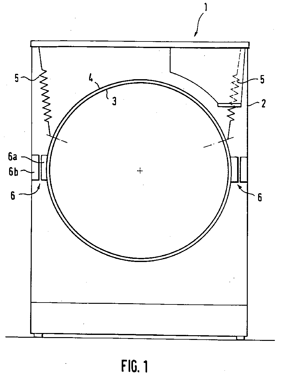
- FIG. 1 shows a washing and / or drying device 1, comprising a housing 2 in which a containing a drum 3 Container 4 is arranged, which is only here sketchy representation.
- the container 4 is shown in the Exemplary embodiment by means of spring suspensions 5 arranged swinging in the housing 2. If the drum is operational is rotated and one inside due to loading given unbalance, the container 4 leads accordingly Movements in the form of vibrations. Around especially in the resonance range, in which the vibrations have extreme amplitudes due to the resonance effect can prevent these vibrations are means 6 provided that serve to fix the container 4.
- This Means 6 comprise a first attached to the outside of the container Part 6a and a fixed, in the example shown second part 6b attached to the housing 2.
- both parts 6a, 6b are spaced apart. This means that cooperation is only possible if the container is in this direction of movement the distance experiences corresponding deflection.
- the means 6 are both in their number and in their arrangement to choose that the vibrating system, i.e. the container, is securely fixed before moving in one direction the allowable amplitude, which then corresponds to Can cause damage.
- the means 6 formed as an adhesive in Form of Velcro strips, which with appropriate deflection of the Attack the container together and so the container in the First fix the correspondingly deflected position.
- the liability of the Velcro connection is limited, it is the Container possible, if that on the connection between parts 6a, 6b acting due to unbalance, those that increase as the spin speed increases Centrifugal force increases and exceeds the adhesive force, to loosen up.
- FIG. 2 shows a device similar to that shown in FIG. 1 constructed washing and / or drying device, wherein on the one hand, another type of fixation device is provided, on the other hand, these funds are in another Direction of movement of the container provided.
- This one shown means 7 is a permanent magnetic means consisting from a first attached to the outside of the container Part 7a, for example the permanent magnetic part, and one fixed on the top or bottom of the housing attached, e.g. B. made of magnetizable material second part 7b.
- This is in the embodiment shown pot-shaped, the part 7a in Shape of a pin that engages in the closed pot. If the container now experiences a corresponding deflection, the pin-shaped part 7a begins to move and approaches the second with increasing deflection Part 7b.
- the two are liable Parts 7a, 7b due to magnetic flux to each other and fix the container. Again, the connection is increasing a force between the parts 7a, 7b acting fixation possible. Due to the constructive training the means 7 is a fixation for every possible Direction of movement possible because the parts 7a and 7b adhere to both vertical and horizontal movements to each other.
- FIG. 3 shows a further embodiment of a By means 8, which is designed here as a clamping means.
- This consists of a projecting one arranged on the container cone-shaped first part 8a, which on its front end portion 9 tapered frustoconical is.
- This is assigned a stationary on the housing arranged second part 8b, which has a recess 10 has, which in the front area with a inside tapering, large receiving opening 11 is provided.
- This is also tapered towards the rear tapered area 12, which corresponds to the Area 9 of the first part 8a is formed.
- FIG. 4 shows a further means 13 in the form of a Holding means.
- This also consists of a first part 13a, which has a spherical at its free end Approach 14 is provided.
- Part 13a is a fixed, assigned to the housing part 13b, which in a correspondingly large recess in its front area 15 has, which tapers inwards.
- the recess 15 ends in a spherical cavity 16, which is somewhat is undercut.
- This means becomes advantageous made of plastic, which allows easy snap-in, manufactured.
- the invention is not based on the fixing means shown limited.
- funds are in the form of, for example spring-loaded locking hook or the like possible, that is, there is an undercut on the container provided pin arranged on the housing Opposite is assigned which one is the undercut has engaging catch or the like for example spring-loaded or by means of an actuator can be operated to release the undercut.
Landscapes
- Engineering & Computer Science (AREA)
- Textile Engineering (AREA)
- Main Body Construction Of Washing Machines And Laundry Dryers (AREA)
- Detail Structures Of Washing Machines And Dryers (AREA)
Abstract
Wasch- und/oder Trocknungsvorrichtung, insbesondere Trommelwaschmaschine
(1), mit einer mit Wäsche beladbaren
Trommel (3), welche in einem Laugenbehälter (4) gelagert
und zur Bearbeitung der Wäsche motorisch gedreht wird. Der
Laugenbehälter (4) ist im Maschinengehäuse (2) beweglich
gehaltert. Im Inneren des Maschinengehäuses (2) sind Mittel
(6) zum lösbaren Fixieren des Laugenbehälters (4) vorgesehen.
Durch diese Mittel (6) werden während der Dauer der
Fixierung des Laugenbehälters (4) dessen Schwingungsbewegungen
infolge beladungsbedingter Umwucht weitgehend
verhindert.
Description
Die Erfindung betrifft eine Wasch- und/oder Trocknungsvorrichtung, insbesondere Trommelwaschmaschine, mit einer mit zu bearbeitenden Gegenständen, insbesondere Wäsche beladbaren Trommel, welche in einem Behälter, insbesondere einem Laugenbehälter drehbar angeordnet und zur Bearbeitung der Gegenstände motorisch gedreht wird, wobei der Behälter in einem Gehäuse beweglich gelagert ist, und mit einer den Betrieb steuernden Steuerungseinrichtung.The invention relates to a washing and / or drying device, especially drum washing machine, with a objects to be processed, especially laundry loadable Drum, which in a container, in particular a Suds container rotatably arranged and for processing the Objects is rotated by motor, the container in a housing is movably mounted, and with one operation controlling control device.
Bei derartigen Vorrichtungen mit sich in ihrem Inneren bewegenden Trommeln ergeben sich aus in der Regel herrschenden Unwuchten, die durch eine ungleichmäßige Verteilung der beladenen Gegenstände, beispielsweise der Wäsche, resultieren, Schwierigkeiten hinsichtlich etwaiger Vibrationen und Bewegungen. Zu diesem Zweck ist es bekannt, den die Trommel beinhaltenden Behälter entsprechend aufzuhängen bzw. mittels entsprechender Dämpferelemente zu dämpfen, um die unwuchtbedingten Bewegungen, die der Behälter ausfuhrt, abzufangen und einigermaßen zu verhindern, daß diese in den Boden geleitet werden bzw. das Gehäuse zu schwingen beginnt. Hierdurch wird auch in einem gewissen Grad eine Geräuschdämpfung erreicht. Dieses Schwingen, das bei bekannten Systemen trotz allem auftritt, führt aber zu einer Vielzahl von Problemen. Zum einen ist für jeden Behälter abhängig von der jeweiligen Beladung ein gewisser Resonanzdrehzahlbereich gegeben, in welchem der Behälter Schwingungen mit extremen Amplituden vollführt, die, sofern unkontrolliert, zu Beschädigungen führen können bzw. einen entsprechenden Schwingraum erfordern. Weiterhin ergeben sich aus einer zu großen Schwingung Schaum- und Abpumpprobleme infolge des kontinuierlichen Aufschüttelns des in der Regel mit Waschmittel beladenen Wassers. Auch ergeben sich aus dieser Bewegung Schwierigkeiten hinsichtlich einer Unwuchtmessung, welche häufig zur Gewinnung von Steuerungsparametern erforderlich ist. Auch sind die in den Boden geleiteten Wechselkräfte nach wie vor beachtlich, gleiches gilt für die Geräuschabstrahlung.In such devices with moving inside Drums usually result from prevailing Unbalance caused by an uneven distribution of the loaded objects, for example laundry, result, Difficulties with possible vibrations and Movements. For this purpose it is known that the drum containing container accordingly or by means of appropriate damping elements to dampen the unbalanced Intercept movements made by the container and to some extent prevent this from entering the ground conducted or the housing starts to vibrate. This also results in some degree of noise reduction reached. This swing, that of familiar ones Systems occurs in spite of everything, but leads to a multitude of problems. First, it depends on each container a certain resonance speed range from the respective load given in which the container vibrates with extreme amplitudes, which, if uncontrolled, can lead to damage or a corresponding Vibration space require. Furthermore arise from a large vibration foam and pumping problems due to the continuous shaking of the usually with detergent laden water. Also result from this movement Difficulties with measuring unbalance, which are often required to obtain control parameters is. Also are the alternating forces directed into the ground Remarkable, the same applies to the noise emission.
Der Erfindung liegt damit das Problem zugrunde, eine Wasch- und/oder Trocknungsvorrichtung anzugeben, mittels welcher die eingangs genannten schwingungsbedingten Probleme weitgehend behebbar sind.The invention is therefore based on the problem of a Specify washing and / or drying device by means of which the vibration-related problems mentioned above largely can be remedied.
Zur Lösung dieses Problems ist bei einer Wasch- und/oder Trocknungsvorrichtung der eingangs genannten Art erfindungsgemäß vorgesehen, daß im Inneren des Gehäuses Mittel zum lösbaren Fixieren des bei Trommelrotation bedingt durch eine beladungsbedingte Unwucht zu Schwingungen anregbaren Behälters, dessen Schwingungsbewegung während der Dauer der Fixierung weitgehend verhindernd, vorgesehen sind. To solve this problem is a washing and / or Drying device of the type mentioned in the invention provided that means inside the housing for releasable fixing of the drum rotation caused by a load-related imbalance that can be excited to vibrate Container whose vibratory movement during the period of To largely prevent fixation, are provided.
Erfindungsgemäß weist die Vorrichtung Fixiermittel auf, mittels welcher der Behälter fixierbar ist und auf diese Weise am Schwingen gehindert werden kann. Da damit eine Unterdrückung der zu den eingangs genannten Problemen führenden Ursache durch einfaches Fixieren des Behälters möglich ist, werden somit mit besonderem Vorteil die eingangs genannten Probleme auf einfache Weise beseitigt. Das Mittel ist vorteilhaft unabhängig von der Einbaulage der Trommel und der Lagerart des Behälters, also schwingende Aufhängung oder stehende Anordnung auf Federbeinen oder Federelemente beliebiger Bauart, anwendbar.According to the invention, the device has fixing means by means of which the container can be fixed and on it Way can be prevented from swinging. As a suppression of the problems leading to the problems mentioned at the beginning Cause possible by simply fixing the container is, the above-mentioned are therefore particularly advantageous Problems easily solved. The middle is advantageous regardless of the installation position of the drum and the type of storage of the container, i.e. swinging suspension or standing arrangement on struts or spring elements any design, applicable.
Vor allem um die eingangs genannten resonanzbedingten Probleme zu beseitigen, kann in Weiterbildung der Erfindung vorgesehen sein, daß die Mittel zum Fixieren des Behälters derart ausgebildet und/oder angeordnet sind, daß der schwingende Behälter ab einer vorbestimmten schwingungsbedingten Auslenkung aus der Ruhelage fixiert wird. Denn zur Beseitigung des Resonanzproblems ist es ausreichend, wenn der Behälter dann fixiert wird, wenn sich die Trommeldrehzahl der Resonanzdrehzahl nähert, was sich durch die entsprechende Auslenkung äußert. Die Mittel können dabei vorteilhaft entsprechend angeordnet sein, daß sie dann greifen, wenn der Behälter eben die entsprechende Auslenkung erfährt, das heißt, daß die Mittel insoweit als passive Mittel ausgebildet sind. Alternativ hierzu kann erfindungsgemäß vorgesehen sein, daß die Mittel über ein Steuerelement steuerbar sind, welches insbesondere in Abhängigkeit eines Erfassungsergebnisses (Trommeldrehzahl oder einer anderen Größe) eines die Auslenkung erfassenden Detektorelements die Mittel steuert. Hier handelt es sich also um aktive Mittel, die aktiv die Fixierung des Behälters erwirken, wobei diese Mittel natürlich auch unabhängig von einem Erfassungsergebnis eines Detektorelements arbeiten können und beispielsweise durch eine Zeitkomponente derart gesteuert werden können, daß sie beim Schleuderbetrieb nach Ablauf einer vorbestimmten Zeit, nach welcher sich erfahrungsgemäß die Drehzahl der Resonanzdrehzahl nähert, greifen. Als Steuerelement kann erfindungsgemäß die Steuereinrichtung dienen.Above all about the resonance-related problems mentioned at the beginning can be eliminated in a further development of the invention be provided that the means for fixing the container are designed and / or arranged such that the vibrating containers from a predetermined vibration-related Deflection from the rest position is fixed. Because for Eliminating the resonance problem, it is sufficient if the container is then fixed when the drum speed approaches the resonance speed, which is reflected by the corresponding Deflection expresses. The means can be advantageous be arranged so that they grip, if the container just the appropriate deflection experiences, that is, that the means as passive Means are formed. Alternatively, according to the invention be provided that the means via a control element are controllable, which is dependent in particular of a detection result (drum speed or another Size) of a detector element detecting the deflection controls the funds. So these are active Agents that actively secure the container, these means of course also independently of one Detection result of a detector element can work and controlled for example by a time component in this way can be that in the spin operation after expiry a predetermined time, after which experience has shown the speed approaches the resonance speed. According to the invention, the control device can act as a control element to serve.
Da eine Fixierung des Behälters außerhalb des Resonanzbereichs nicht unbedingt erforderlich oder nachteilig ist, da die Schwingungen dann nicht derart sind, daß die eingangs genannten Probleme im Übermaß auftreten, ist auf Basis der Erfindung ferner vorgesehen, daß die Mittel derart ausgebildet und/oder angeordnet sind, daß der fixierte Behälter bei Vorherrschen einer auf das Mittel wirkenden, unwuchtbedingt von der Trommelrotation herrührenden vorgegebenen Kraft oder eines Moments lösbar ist. Der Behälter löst sich bzw. wird mit besonderem Vorteil dann gelöst, wenn die unwuchtbedingt auf das Mittel ausgeübte Kraft einen vorbei stimmten Wert überschreitet, welcher natürlich derart bemessen ist, daß der Resonanzbereich verlassen ist, so daß nach dem Lösen keine unzulässig großen Schwingungsamplituden auftreten können. Sofern es sich um ein aktives Mittel handelt, kann auf Basis der Erfindung ferner wenigstens eine dem oder den Mitteln zugeordnete Einrichtung zum Bestimmen der wirkenden Kraft oder des Moments vorgesehen sein, abhängig von deren Bestimmungsergebnis das Mittel über das Steuerungselement steuerbar ist. In diesem Fall wird also die Kraft, die auf das Mittel wirkt, direkt bestimmt, das heißt, die vorgegebene, das Lösen bewirkende Kraft ist nicht von der Konstruktion des Mittels selbst vorgegeben. Im Falle eines aktiven Elements kann die Steuerung natürlich auch kraftunabhängig erfolgen, beispielsweise durch Zeitablaufssteuerung oder drehzahlabhängig derart, daß nach Ablauf einer vorgegebenen Zeit, nach welcher es sicher ist, daß die Resonanzdrehzahl überschritten ist, gelöst wird.Because a fixation of the container outside the resonance range is not absolutely necessary or disadvantageous because then the vibrations are not such that the input problems mentioned in excess, is based on the Invention further provided that the means are designed in this way and / or arranged that the fixed container if there is an imbalance that acts on the agent predetermined from the drum rotation Force or a moment is releasable. The container comes off or will be solved with particular advantage if the unbalance force exerted on the remedy will pass you by exceeds the agreed value, which of course is measured in this way is that the resonance range is left, so that after loosening, no impermissibly large vibration amplitudes may occur. Unless it is an active agent acts, based on the invention at least one device for determining assigned to the means the acting force or the moment can be provided, depending on the result of their determination, the mean over the Control element is controllable. So in this case the force that acts on the agent directly determines that means that the predetermined force that brings about loosening is not determined by the construction of the agent itself. In the case of an active element, the control can of course also take place independently of force, for example by Timing control or speed-dependent such that after Expiry of a predetermined time, after which it is certain that the resonance speed is exceeded is solved.
Im Rahmen einer ersten Erfindungsalternative kann vorgesehen sein, daß die Mittel als permanentmagnetische oder elektromagnetische Mittel ausgebildet sind, wobei diese sowohl als passive als auch als aktive Mittel fungieren können. Beispielsweise kann das permanentmagnetische Mittel dergestalt ausgebildet sein, daß es zur Ausübung seiner Magnetkraft aktiv in den Behälterbereich transportiert wird, um diesen zu fixieren, gleiches gilt für das elektromagnetische Mittel, welches ohnehin als aktives Mittel angesteuert werden muß. Alternativ hierzu kann vorgesehen sein, daß die Mittel als Klemm-, Rast- oder Haftmittel ausgebildet sind. Als zweckmäßig hat es sich hierbei erwiesen, wenn die Mittel einen am Behälter angeordneten ersten und einen feststehenden, insbesondere am Gehäuse angeordneten zweiten Teil aufweisen. Als Klemm-, Rast- oder Haftmittel können sämtliche einer hinreichend festen Verbindung dienenden Konstruktionen verwendet werden, beispielsweise in Form von miteinander eingreifenden keilförmigen Klemmelementen, oder aber ein Klettband, welches sowohl am Gehäuse als auch am Behälter angebracht ist und bei Zusammenfügen der beiden Teile eine hinreichende Verbindung liefert. Auch eine Haftmittelausbildung in Form eines Saugnapfes, also eines mit Unterdruck arbeitenden Mittels ist denkbar. Die Rastmittel können jedwede Rastverbindung, die ein sicheres Eingreifen bei gleichzeitiger Lösbarkeit liefert, umfassen.Within the scope of a first alternative of the invention, provision can be made be that the means as permanent magnetic or electromagnetic means are formed, these both can act as both passive and active agents. For example, the permanent magnetic means be designed so that it can exert its magnetic force is actively transported to the container area, to fix this, the same applies to the electromagnetic Means, which are already controlled as active means must become. Alternatively, it can be provided that the means are designed as clamping, locking or adhesive means are. It has proven to be useful here if the Means a first and a one arranged on the container fixed, in particular arranged on the housing second Have part. Can be used as a clamping, locking or adhesive all serving a sufficiently firm connection Constructions are used, for example in the form of interlocking wedge-shaped clamping elements, or but a Velcro tape that is attached to both the housing and the Container is attached and when the two are put together Parts provides a sufficient connection. Also an adhesive training in the form of a suction cup, i.e. one with Vacuum working means is conceivable. The locking means can any latching connection that a safe intervention provides at the same time solvability.
Weitere Vorteile, Merkmale und Einzelheiten der Erfindung ergeben sich aus den im folgenden beschriebenen Ausführungsbeispielen sowie anhand der Zeichnungen. Dabei zeigen:
- Fig. 1
- eine erste Ausführungsform mit Fixiermitteln beispielsweise in Form eines Klettbandes,
- Fig. 2
- eine zweite Ausführungsform in Form eines Permanentmagneten,
- Fig. 3
- eine Prinzipsskizze einer weiteren Ausführungsform eines als Klemmittel ausgebildeten Mittels, und
- Fig. 4
- eine weitere Ausführungsform eines als Rastmittel ausgebildeten Mittels.
- Fig. 1
- a first embodiment with fixing means, for example in the form of a Velcro strip,
- Fig. 2
- a second embodiment in the form of a permanent magnet,
- Fig. 3
- a schematic diagram of a further embodiment of a means designed as a clamping means, and
- Fig. 4
- a further embodiment of a means designed as a locking means.
Fig. 1 zeigt eine Wasch- und/oder Trocknungsvorrichtung 1,
umfassend ein Gehäuse 2, in dem ein eine Trommel 3 beinhaltender
Behälter 4 angeordnet ist, wobei es sich hier nur um
skizzenhafte Darstellung handelt. Der Behälter 4 ist im gezeigten
Ausführungsbeispiel mittels Federaufhängungen 5
schwingend im Gehäuse 2 angeordnet. Sofern die Trommel betriebsbedingt
gedreht wird und eine im Inneren beladungsbedingt
gegebene Unwucht vorliegt, führt der Behälter 4 entsprechende
Bewegungen in Form von Schwingungen durch. Um
insbesondere im Resonanzbereich, in welchem die Schwingungen
aufgrund der Resonanzwirkung extreme Amplituden besitzen
können, diese Schwingungen zu verhindern, sind Mittel 6
vorgesehen, die zum Fixieren des Behälters 4 dienen. Diese
Mittel 6 umfassen einen am Behälteräußeren angebrachten ersten
Teil 6a und einen feststehenden, im gezeigten Beispiel
am Gehäuse 2 angebrachten zweiten Teil 6b. Wie der Figur zu
entnehmen ist, sind beide Teile 6a, 6b voneinander beabstandet.
Das heißt, ein Zusammenwirken ist erst möglich,
wenn der Behälter in dieser Bewegungsrichtung eine dem Abstand
entsprechende Auslenkung erfährt. Die Mittel 6 sind
dabei sowohl in ihrer Zahl als auch in ihrer Anordnung derart
zu wählen, daß das schwingende System, also der Behälter,
sicher fixiert wird, bevor er in einer Bewegungsrichtung
die zulässige Amplitude, die dann zu entsprechenden
Beschädigungen führen kann, überschreitet. Im gezeigten
Beispiel ist das Mittel 6 als Haftmittel ausgebildet in
Form von Klettbändern, die bei entsprechendem Auslenken des
Behälters miteinander angreifen und so den Behälter in der
entsprechend ausgelenkten Stellung zunächst fixieren. Da
die Haftung der Klettverbindung begrenzt ist, ist es dem
Behälter möglich, dann, wenn die auf die Verbindung zwischen
den Teilen 6a, 6b wirkende, unwuchtbedingte Kraft,
die infolge der mit zunehmender Schleuderdrehzahl ansteigenden
Zentrifugalkraft zunimmt und die Haftkaft übersteigt,
sich zu lösen.1 shows a washing and / or
Fig. 2 zeigt eine ähnlich der in Fig. 1 gezeigten Vorrichtung
aufgebaute Wasch- und/oder Trocknungsvorrichtung, wobei
hier einerseits eine andere Art von Mittel zum Fixieren
vorgesehen ist, zum anderen sind diese Mittel in einer anderen
Bewegungsrichtung des Behälters vorgesehen. Das hier
gezeigte Mittel 7 ist ein permanentmagnetisches Mittel, bestehend
aus einem am Behälteräußeren angebrachten ersten
Teil 7a, beispielsweise dem permanentmagnetischen Teil, und
einem am Gehäuse oberseitig bzw. unterseitig feststehend
angebrachten, z. B. aus magnetisierbarem Material bestehenden
zweiten Teil 7b. Dieses ist im gezeigten Ausführungsbeispiel
topfförmig ausgebildet, das Teil 7a dagegen in
Form eines Zapfens, welcher in den geschlossenen Topf eingreift.
Erfährt nun der Behälter eine entsprechende Auslenkung,
beginnt sich der zapfenförmige Teil 7a zu bewegen und
nähert sich mit zunehmender Auslenkung immer mehr dem zweiten
Teil 7b. Ist die Auslenkung groß genug, haften die beiden
Teile 7a, 7b magnetflußbedingt aneinander und fixieren
den Behälter. Auch hier ist mit zunehmender auf die Verbindung
zwischen den Teilen 7a, 7b wirkender Kraft ein Lösen
der Fixierung möglich. Bedingt duch die konstruktive Ausbildung
des Mittels 7 ist hier eine Fixierung für jede mögliche
Bewegungsrichtung möglich, denn die Teile 7a und 7b
haften sowohl bei Vertikal- wie auch bei Horizontalbewegung
aneinander.FIG. 2 shows a device similar to that shown in FIG. 1
constructed washing and / or drying device, wherein
on the one hand, another type of fixation device
is provided, on the other hand, these funds are in another
Direction of movement of the container provided. This one
shown means 7 is a permanent magnetic means consisting
from a first attached to the outside of the
Fig. 3 zeigt schließlich eine weitere Ausführungsform eines
Mittels 8, welches hier als Klemmittel ausgebildet ist.
Dieses besteht aus einem am Behälter angeordneten, vorspringenden
zapfenförmigen ersten Teil 8a, welches an seinem
vorderen Endbereich 9 kegelstumpfförmig verjüngt ausgebildet
ist. Diesem zugeordnet ist ein am Gehäuse feststehend
angeordnetes zweites Teil 8b, welches eine Ausnehmung
10 aufweist, die im vorderen Bereich mit einer sich nach
innen verjüngenden, großen Aufnahmeöffnung 11 versehen ist.
An diese schließt sich ein sich ebenfalls nach hinten konisch
verjüngender Bereich 12 an, welcher entsprechend dem
Bereich 9 des ersten Teils 8a ausgebildet ist. Bewegt sich
nun das erste Teil 8a schwingungsbedingt in das Innere des
zweiten Teils 8b, so verklemmen beide Teile miteinander,
wenn die Bereiche 9 und 12 in Berührung miteinander kommen.
Auch hier ist ein Lösen dann wieder möglich, wenn die auf
die Verbindung wirkende Kraft größer als die Klemmkraft
ist. 3 shows a further embodiment of a
By means 8, which is designed here as a clamping means.
This consists of a projecting one arranged on the container
cone-shaped
Schließlich zeigt Fig. 4 ein weiteres Mittel 13 in Form eines
Haltemittels. Auch dieses besteht aus einem ersten Teil
13a, welches an seinem freien Ende mit einem kugelförmigen
Ansatz 14 versehen ist. Dem Teil 13a ist ein feststehendes,
am Gehäuse angeordnetes Teil 13b zugeordnet, welches in
seinem vorderen Bereich eine entsprechend große Ausnehmung
15 aufweist, die sich nach innen verjüngt. Die Ausnehmung
15 endet in einem kugelförmigen Hohlraum 16, welcher etwas
hinterschnitten ist. Wird nun schwingungsbedingt das Teil
13a in das Innere des Teils 13b bewegt, so rastet bei hinreichender
Auslenkung der Ansatz 14 in den Hohlraum 16 ein
und wird durch die Hinterschneidung dort fixiert. Bei entsprechend
großer Kraft ist auch hier ein Herausziehen und
damit ein Lösen wiederum möglich. Dieses Mittel wird vorteilhaft
aus Kunststoff, der ein einfaches Einrasten ermöglicht,
gefertigt.Finally, FIG. 4 shows a further means 13 in the form of a
Holding means. This also consists of a
Die Erfindung ist nicht auf die dargestellten Fixiermittel beschränkt. Gleichermaßen sind Mittel in Form von beispielsweise federbeaufschlagten Rasthaken oder dergleichen möglich, das heißt, am Behälter ist ein mit einer Hinterschneidung versehener Zapfen angeordnet, dem am Gehäuse ein Gegenüber zugeordnet ist, welches eine die Hinterschneidung hintergreifende Rastnase oder dergleichen aufweist, die beispielsweise federbelastet oder aber mittels eines Stellgliedes betätigt werden kann, um die Hinterschneidung freizugeben.The invention is not based on the fixing means shown limited. Similarly, funds are in the form of, for example spring-loaded locking hook or the like possible, that is, there is an undercut on the container provided pin arranged on the housing Opposite is assigned which one is the undercut has engaging catch or the like for example spring-loaded or by means of an actuator can be operated to release the undercut.
Claims (9)
Applications Claiming Priority (2)
| Application Number | Priority Date | Filing Date | Title |
|---|---|---|---|
| DE19641476 | 1996-10-09 | ||
| DE19641476A DE19641476A1 (en) | 1996-10-09 | 1996-10-09 | Washing and / or drying device, in particular drum washing machine |
Publications (2)
| Publication Number | Publication Date |
|---|---|
| EP0835954A2 true EP0835954A2 (en) | 1998-04-15 |
| EP0835954A3 EP0835954A3 (en) | 1998-10-14 |
Family
ID=7808183
Family Applications (1)
| Application Number | Title | Priority Date | Filing Date |
|---|---|---|---|
| EP97117304A Withdrawn EP0835954A3 (en) | 1996-10-09 | 1997-10-07 | Device for washing and/or drying, in particular drum washing machine |
Country Status (2)
| Country | Link |
|---|---|
| EP (1) | EP0835954A3 (en) |
| DE (1) | DE19641476A1 (en) |
Cited By (2)
| Publication number | Priority date | Publication date | Assignee | Title |
|---|---|---|---|---|
| EP1275765A1 (en) * | 2001-07-13 | 2003-01-15 | Otto Diethelm | Electronic balancing for washing machines, washdryer, laundry dryer etc |
| EP1666763A4 (en) * | 2003-09-10 | 2008-10-22 | Sintokogio Ltd | Device and method for damping vibration of rotating shaft system |
Family Cites Families (7)
| Publication number | Priority date | Publication date | Assignee | Title |
|---|---|---|---|---|
| DE1460969A1 (en) * | 1954-07-01 | 1969-04-24 | Hotchkiss Brandt | Dry friction damper for washing machines with washing drum |
| DD119628A1 (en) * | 1975-02-25 | 1976-05-05 | ||
| JPH0323894A (en) * | 1989-06-20 | 1991-01-31 | Mitsubishi Heavy Ind Ltd | Drum type washing and hydro-extracting machine |
| JPH04197293A (en) * | 1990-11-28 | 1992-07-16 | Matsushita Electric Ind Co Ltd | Oscillation preventing device of outer tank of automatic washing machine |
| KR930010163B1 (en) * | 1991-01-26 | 1993-10-15 | 삼성전자 주식회사 | Washing machine controller |
| IT1251309B (en) * | 1991-09-12 | 1995-05-08 | Whirlpool Italia | WASHING MACHINE DRIER OR SIMILAR PRESENTING MAGNETIC SHOCK ABSORBERS |
| US5427347A (en) * | 1993-04-08 | 1995-06-27 | Lord Corporation | Apparatus for controlling active mounts |
-
1996
- 1996-10-09 DE DE19641476A patent/DE19641476A1/en not_active Withdrawn
-
1997
- 1997-10-07 EP EP97117304A patent/EP0835954A3/en not_active Withdrawn
Cited By (2)
| Publication number | Priority date | Publication date | Assignee | Title |
|---|---|---|---|---|
| EP1275765A1 (en) * | 2001-07-13 | 2003-01-15 | Otto Diethelm | Electronic balancing for washing machines, washdryer, laundry dryer etc |
| EP1666763A4 (en) * | 2003-09-10 | 2008-10-22 | Sintokogio Ltd | Device and method for damping vibration of rotating shaft system |
Also Published As
| Publication number | Publication date |
|---|---|
| DE19641476A1 (en) | 1998-04-16 |
| EP0835954A3 (en) | 1998-10-14 |
Similar Documents
| Publication | Publication Date | Title |
|---|---|---|
| DE69806100T2 (en) | Process for actively damping vibrations in washing machines and washing machines for carrying out this process | |
| DE69520584T2 (en) | DEVICE FOR BALANCING A BODY SWIVELING A HORIZONTAL AXIS | |
| EP2217752B1 (en) | Method and device for determining the optimal rotational speed of a drum of a laundry treatment device | |
| EP1067233B1 (en) | Method for measuring the load in a washing machine drum | |
| EP3294941B1 (en) | Method for determining the mass as a laundry batch is introduced into a laundry drum, and laundry treatment machine for performing the method | |
| WO2008101549A1 (en) | Laundry treatment device | |
| DE4201904C2 (en) | Vibration damping device for a washing machine or the like | |
| DE2204325A1 (en) | SPIN DRUM WASHING MACHINE | |
| DE102006032337A1 (en) | Method for controlling a spin cycle of a washing machine and suitable for performing the method suitable washing machine | |
| EP2010705A1 (en) | Machine for washing and/or drying laundry | |
| DE60310917T2 (en) | AUTOMATIC BALANCING DEVICE | |
| DE4329176C2 (en) | Foot for supporting a frame of a machine with a vibrator | |
| DE102008039569A1 (en) | Drum suspension device for washing device, has actuator formed to change damping characteristic of damping device or spring characteristic of spring device depending on control signals of control device | |
| DE69029611T2 (en) | Drum washing machine and tumble dryer | |
| EP0835954A2 (en) | Device for washing and/or drying, in particular drum washing machine | |
| DE4439153C2 (en) | Drum washing machine with a swing-mounted washing unit | |
| DE102018210562A1 (en) | Washing machine with balance ring | |
| DE3741791C3 (en) | Procedure for determining the unbalance of laundry in drum washing machines | |
| DE2406682A1 (en) | VOT AND DRUM OF A WASHING MACHINE | |
| DE60014191T2 (en) | Rotating machines with an imbalance of operation | |
| DE102014001676A1 (en) | Laundry treatment device with imbalance detection device and method for detecting an imbalance in a laundry treatment device | |
| EP2379787B1 (en) | Method for determining a static and a dynamic imbalance, corresponding device and household appliance comprising said device | |
| DE69802050T2 (en) | Elastic hanging device for washing machine | |
| DE102017219081A1 (en) | Method for operating a domestic appliance for the care of laundry items with detection of an imbalance based on two input channels and household appliance | |
| EP0376919A2 (en) | Decanter with a vibration upsetting component |
Legal Events
| Date | Code | Title | Description |
|---|---|---|---|
| PUAI | Public reference made under article 153(3) epc to a published international application that has entered the european phase |
Free format text: ORIGINAL CODE: 0009012 |
|
| AK | Designated contracting states |
Kind code of ref document: A2 Designated state(s): DE FR IT NL |
|
| AX | Request for extension of the european patent |
Free format text: AL;LT;LV;RO;SI |
|
| PUAL | Search report despatched |
Free format text: ORIGINAL CODE: 0009013 |
|
| AK | Designated contracting states |
Kind code of ref document: A3 Designated state(s): AT BE CH DE DK ES FI FR GB GR IE IT LI LU MC NL PT SE |
|
| AX | Request for extension of the european patent |
Free format text: AL;LT;LV;RO;SI |
|
| AKX | Designation fees paid |
Free format text: DE FR IT NL |
|
| STAA | Information on the status of an ep patent application or granted ep patent |
Free format text: STATUS: THE APPLICATION IS DEEMED TO BE WITHDRAWN |
|
| 18D | Application deemed to be withdrawn |
Effective date: 19990415 |