EP0835966A1 - Elément pour façade avec parement décoratif - Google Patents
Elément pour façade avec parement décoratif Download PDFInfo
- Publication number
- EP0835966A1 EP0835966A1 EP97402338A EP97402338A EP0835966A1 EP 0835966 A1 EP0835966 A1 EP 0835966A1 EP 97402338 A EP97402338 A EP 97402338A EP 97402338 A EP97402338 A EP 97402338A EP 0835966 A1 EP0835966 A1 EP 0835966A1
- Authority
- EP
- European Patent Office
- Prior art keywords
- facade
- support
- fixing
- panel
- wall
- Prior art date
- Legal status (The legal status is an assumption and is not a legal conclusion. Google has not performed a legal analysis and makes no representation as to the accuracy of the status listed.)
- Withdrawn
Links
- 239000000463 material Substances 0.000 claims description 9
- 238000010276 construction Methods 0.000 claims description 7
- 238000006073 displacement reaction Methods 0.000 claims description 4
- 239000004033 plastic Substances 0.000 claims description 4
- 229920003023 plastic Polymers 0.000 claims description 4
- XLYOFNOQVPJJNP-UHFFFAOYSA-N water Substances O XLYOFNOQVPJJNP-UHFFFAOYSA-N 0.000 claims description 3
- 239000011810 insulating material Substances 0.000 claims description 2
- 239000007787 solid Substances 0.000 claims 1
- 230000002787 reinforcement Effects 0.000 description 15
- 229910052751 metal Inorganic materials 0.000 description 6
- 239000002184 metal Substances 0.000 description 6
- 239000003570 air Substances 0.000 description 3
- 229910052782 aluminium Inorganic materials 0.000 description 2
- XAGFODPZIPBFFR-UHFFFAOYSA-N aluminium Chemical compound [Al] XAGFODPZIPBFFR-UHFFFAOYSA-N 0.000 description 2
- 230000001413 cellular effect Effects 0.000 description 2
- 229920003051 synthetic elastomer Polymers 0.000 description 2
- 239000005061 synthetic rubber Substances 0.000 description 2
- 229910000831 Steel Inorganic materials 0.000 description 1
- 239000012080 ambient air Substances 0.000 description 1
- 238000013459 approach Methods 0.000 description 1
- 239000003086 colorant Substances 0.000 description 1
- 230000010339 dilation Effects 0.000 description 1
- 239000000945 filler Substances 0.000 description 1
- 239000006260 foam Substances 0.000 description 1
- 239000004570 mortar (masonry) Substances 0.000 description 1
- 229920002635 polyurethane Polymers 0.000 description 1
- 239000004814 polyurethane Substances 0.000 description 1
- 230000000717 retained effect Effects 0.000 description 1
- 239000010959 steel Substances 0.000 description 1
Images



Classifications
-
- E—FIXED CONSTRUCTIONS
- E04—BUILDING
- E04B—GENERAL BUILDING CONSTRUCTIONS; WALLS, e.g. PARTITIONS; ROOFS; FLOORS; CEILINGS; INSULATION OR OTHER PROTECTION OF BUILDINGS
- E04B2/00—Walls, e.g. partitions, for buildings; Wall construction with regard to insulation; Connections specially adapted to walls
- E04B2/88—Curtain walls
- E04B2/90—Curtain walls comprising panels directly attached to the structure
- E04B2/92—Sandwich-type panels
-
- E—FIXED CONSTRUCTIONS
- E04—BUILDING
- E04F—FINISHING WORK ON BUILDINGS, e.g. STAIRS, FLOORS
- E04F13/00—Coverings or linings, e.g. for walls or ceilings
- E04F13/07—Coverings or linings, e.g. for walls or ceilings composed of covering or lining elements; Sub-structures therefor; Fastening means therefor
- E04F13/08—Coverings or linings, e.g. for walls or ceilings composed of covering or lining elements; Sub-structures therefor; Fastening means therefor composed of a plurality of similar covering or lining elements
- E04F13/0801—Separate fastening elements
- E04F13/0803—Separate fastening elements with load-supporting elongated furring elements between wall and covering elements
- E04F13/081—Separate fastening elements with load-supporting elongated furring elements between wall and covering elements with additional fastening elements between furring elements and covering elements
Definitions
- the invention relates to building facades and elements for such facades.
- An object of the invention is to propose an element for facades in which the panel is fixed so reliable and simple to support.
- a facade element comprising a support and a panel comprising at least two parts of fixing fixed to the support and a wall generally plane extending between the two fixing parts, in which at least one of the fixing parts extends back from the wall plane and is deformable so that the wall is free to move parallel to itself with respect to the support during a change in the panel temperature.
- the support comprises a core having at least one lateral face extending along a general direction perpendicular to the wall of the panel, the support comprising means for fixing the or each fixing part extending opposite and away from the lateral face of the core.
- the fixing means are connected to a rear face of the core opposite the wall of the sign.
- the fixing means are arranged to receive the fixing part during a relative displacement of the support relative to the panel perpendicular to the wall.
- the support has a surface guide adapted to guide the fixing part from a position close to the fixing means up to these during a relative displacement of the support by relation to the panel perpendicular to the wall.
- the guide surface is shaped to distance the fixing parts one of the other when moving the support.
- the fixing part is allowed to stand deform by a large amplitude during a wall dilation.
- the support comprises a first and second assembly parts constituting the fixing means, the first assembly part being attached to the core and extending opposite it and the second assembly piece extending to the outside of the element and being attached to the first assembly piece with interposition of a seal of thermal insulating material. So, we limits heat transfers since the second assembly part in direct contact with the ambient air, and the first assembly part adjacent to the core.
- the first assembly part is profiled and extends along a lateral face of blade.
- the first assembly part constitutes a reinforcement piece improving mechanical strength of soul.
- the core comprises a material alveolar.
- the panel comprises a material full plastic.
- the panel can assume very varied according to the aesthetics desired for the facade.
- a assembly for the construction of a facade comprising two facade elements according to the invention and a gasket connection adapted to be fixed to the two facade elements when these are arranged adjacent to one another the other, so as to prevent the passage of air between the two facade elements in a direction perpendicular to the walls of the panels.
- each facade element has a lap joint arranged so that the overlap joints of two facade elements arranged adjacent to each other come in contact with each other so as to prohibit splashes of water between the two elements of facade in a direction perpendicular to the walls Signs.
- the second assembly part is suitable for receiving at least one of the joints among the cover and link joints.
- a facade is provided according to the invention. comprising facade elements according to the invention, or an assembly according to the invention.
- the facade in this embodiment of the invention, is attached to a building comprising several horizontal floors 2 made up mainly concrete and extending to levels different, one above the other. These floors 2 each have a vertical straight edge 4, these edges being parallel to each other and inscribed in a same vertical plane. The facade extends against these edges 4. Each floor 2 has two flat faces horizontal upper 5 and lower 6.
- the facade contains the first elements of facade or trumeaux 8 and second facade elements or fillers 10.
- Each of these has a general shape of a rectangular parallelepiped having in particular a large front face 12 and a large rear face 14 generally flat and parallel between them.
- Each first and second facade elements 8, 10 comprises a honeycomb core 16, for example made of foam polyurethane.
- the core 16 has a front face 15 and a rear face 17, parallel to each other and covered by two respective metal sheets having a thickness of 0.05 mm.
- Soul 16 has two flat rectilinear side faces 20 parallel between them and extending vertically.
- On each side side 20 is associated with a rigid profiled reinforcement 22 in galvanized sheet, 2.5 mm thick, covering the face side and part of the front 15 and rear 17 faces of soul.
- the reinforcement 22 is fixed to the rear face 17 of the core 16 oriented towards the floors 2 with interposition of the metal sheet, making a surface-to-surface contact with it. He's stretching over the entire height of the rear face 17 of the core.
- the filling elements 10 include in addition to two horizontal rigid profile reinforcements 24 associated in the same way with two rectilinear faces upper and lower horizontal planes of the core 16.
- Each of the first and second elements of front 8, 10 has a facing panel 25 in plastic material, for example PVC, extending look of the front face 15 of the core 16, parallel to this and hiding it from view from the outside of the building.
- the facing panel 25 extends from the side exterior of the facade element to be visible from outside the building. It has a face plane 12 constituting the front face of the element of facade.
- the facade also has joinery such as windows 26 or doors, shaped general planar and rectangular in elevation.
- the first and second facade elements 8, 10 and the joinery 26 are arranged next to each other others in the same plane adjacent to the edges 4 of floors 2.
- the first facade elements 8 are fixed to the floors 2 and only to these, by means of first fasteners or brackets 30.
- the first facade elements 8 are arranged in several vertical rows parallel to each other, spaced apart each other.
- the first facade elements 8 of each row are adjacent to each other and have their vertical side faces aligned.
- Each first facade element 8 has a dimension longitudinal or height h in the direction vertical perpendicular to the floors 3. This dimension h is equal to the distance d between the faces counterparts (for example the upper faces 5) of two floors 2 adjacent to each other according to the vertical direction. This distance d is the height of a floor of the building.
- Each first facade element 8 is fixed to two adjacent floors 2 extending to levels different. It is attached to each of these floors by two brackets 30 which also fix to this same floor 2 the first front element 8 following in the row.
- Each bracket 30 has a first and a second plates 32, 34 fixed to each other in forming a right angle.
- the first plate 32 comprises four through holes 44 for fixing to the square of the first two facade elements 8, each by two screws or rivets passing through two of the holes 44.
- the first plate 32 extends vertically, parallel to the rear face 17 of the core and is fixed to each of the first two facade elements 8, by example by means of two screws or rivets with axis 90.
- One rods through the core 16 right through following its thickness and is connected to one of the rigid reinforcements vertical 22 on either side of the core, and the other rod passes through the reinforcement 22 and the core 16.
- the second plate 34 extends horizontally and is embedded in the floor 2.
- the second plate 34 has three circular threaded housings 38 running through the thickness of the plate and arranged in a triangle.
- the square comprises three needle screws 40 engaged in the respective housings 38 so as to project of a face of the second plate 34 opposite the first deck 32.
- the bracket 30 is set up in the way next.
- a horizontal concrete slab 36 constituting the main structure of floor 2, sparing in this slab a rebate adjacent to edge 4 of the floor and having a flat face 37 generally horizontal.
- the second plate 34 has two orifices 42, one of which is close to the first stage 32, and long, and the other is far from the first circular plate, and two screws joining 39 engaged in the orifices 42 respective.
- we sink into the rebate one filling material such as mortar 41, filling all the rebate and covering the second plate horizontal 34 without covering the first plate vertical 32. This material immobilizes the square after hardening.
- one or more wedges 43 can be interposed between the second horizontal plate 34 and the upper face 37 of the rebate.
- the 30 brackets have dimensions very much smaller than the first and second facade elements 8, 10 according to the horizontal and vertical directions, including smaller than the largest dimension of these elements.
- the second facade elements 10 and the joinery 26 have the same horizontal dimensions or length, and are arranged in several rows vertical spaced from each other and alternating with the rows of the first facade elements 8. In each row, the second facade elements 10 and joinery 26 are alternated and have their faces vertical sides aligned with each other.
- the second façade elements 10 have a vertical dimension or height f
- the joinery 26 has a vertical dimension or height g. The sum of the height f and the height g is equal to the height h of first facade elements 8.
- Each second facade element 10 extends in look of the first two facade elements 8 of each adjacent row. Each second facade element 10 is attached to these first four facade elements 8 and only to these. Each joinery 26 is fixed to a first facade element 8 of each adjacent row and only to these.
- the fixing of the second facade elements 10 is carried out by means of second fasteners such as elongated flat metal legs horizontal 46 fixed to the vertical reinforcements 22 of the first facade elements 8.
- Leg 46 has six through holes 48. Two of these holes 48 receive fasteners such as screws or rivets of axis 95 passing through a vertical reinforcement 22 and the core 16 of the first associated facade element 8.
- a third orifice 48 receives a pin attachment 96 passing through a vertical reinforcement 22 and the core 16 of the second element of facade 10.
- Two other orifices 48 receive two axis 97 fasteners passing through one of the reinforcements horizontal 24 of the second facade element 10.
- the panels 25 of the first facade elements 8 have a profile in vertical section transverse to the front, such that the panel has an upper zone 25a which is close to the core 16 and a lower zone 25b which is distant from the core, and covers by outside the upper zone 25a of the first element of facade 8 adjacent in the row.
- This facade is therefore constructed by means of a assembly comprising first elements 8 comprising a cellular core 16 and adapted to be fixed to a building, second elements 10, and means for attachment 30 of the second elements 10 to the first elements 8, with the first and second elements 8, 10 extending in the same plane.
- This construction is carried out by fixing the first elements 8 to the building, arranging the first elements 8 and second elements 10 in one same vertical plane, and fixing the second elements 10 to the first elements 8.
- the facade thus obtained has a low weight and is qualified as light.
- each of the first and second facade elements comprises a core 16, in general shape of a rectangular parallelepiped, presenting two large front faces 15 and rear 17 planes and mutually parallel, two flat lateral faces 20, parallel to each other, perpendicular to large faces 15 and 17, intended to extend vertically, and two plane end faces parallel to each other, perpendicular to the large faces 15 and 17 and intended to extend horizontally.
- Each large face 15, 17 is covered by a metal sheet.
- the facade element has two reinforcements metal profiles or first assembly part 22.
- Each reinforcement 22 has a shaped transverse profile general of "U”, having a base 50, a branch front 52 and a rear branch 54, the branches being parallel to each other. The front and rear are separated from each other by a distance slightly greater than the thickness of the core 16, at find out the distance between the two large front faces 15 and rear 17 of the core.
- Reinforcement 22 has a length close to that of the vertical side faces 20 of blade.
- Each reinforcement 22 is arranged to cover one of the lateral faces 20 of the core, the front branch 52 coming opposite the front face 15, the branch rear 54 facing the rear face 17 and the base 50 coming opposite the lateral face 20.
- the rear branch 54 is fixed to the rear face 17 of the soul, through the metal sheet, at least two longitudinal ends of the reinforcement 22, this branch making surface-to-surface contact with this face.
- the front branch 52 extends parallel to distance from and facing the front face 15, and the base 50 extends opposite and at a distance from the lateral face 20.
- the base 50 has an "S" profile from one to the other of the two branches 52, 54. From the branch front 52 to rear branch 54, base 50 has a first flat portion 50a which moves away from the side face 20 while being inclined, then a second middle portion 50b which approaches the lateral face 20, and a third flat portion 50c parallel to the lateral face 20.
- the facade element has two second assembly parts 60 associated with the first parts respective assembly 22.
- Each second piece 60 is made of aluminum, is profiled and has a length equal to that of the first assembly part 22.
- the second assembly part 60 has a profile transverse in "S" similar to that of branch 50 of the first assembly part 22, with a first portion 60a, a second portion 60b and a third portion 60c.
- the third portion 50c of the first piece of assembly and an area of the third portion 60c of the second assembly piece have substantially even shape and same dimensions. They are fixed one to the other, for example by means of screws or pin rivets 70 regularly spaced along the profiles and crossing right through with interposition on all their length from an interposition joint 62 in synthetic rubber forming a thermal break between the two connecting pieces 22 and 60.
- the second middle portions 50b and 60b lie opposite each other. Both first portions 50a and 60a extend opposite one on the other by being parallel to each other.
- the core 16 and the four assembly pieces 22, 60 of the element constitute a support for the element.
- the facade element has a panel 25 comprising a rectangular flat wall 66 having dimensions close to those of the large faces 15, 17 of the core 16. A front face 12 of this wall is intended to be visible from the outside of the facade.
- the panel includes four edges 68 of planar shape, extending from the sides of the rectangle of the wall 66, and opposite two by two on either side thereof.
- the edges 68 generally extend perpendicular to the wall 66 and set back from the plane of it, on the side opposite to the visible face 12.
- Each edge 68 is slightly inclined in the opposite direction to the edge 68 facing him.
- the two edges 68 intended to extend vertically constitute two fixing parts of the panel 25 to the support, these two parts extending to distance from each other and at two ends of the sign.
- the two connecting pieces 22, 60 adjacent to each edge 68 constitute means for fixing this edge to support.
- the edge 68 is intended to be inserted between the first two portions 50a and 60a to be pinched between them and retained by the reliefs 64.
- the first portion 50a of the first assembly part 22 is more strongly inclined with respect to the face lateral 20 of the core than the associated edge 68.
- She constitutes a guide surface adapted to guide the edge 68 from a position close to the means of fixing to these, the panel 25 being fixed to the support by embedding by means of a displacement relative of the support relative to the panel 25 according to a direction perpendicular to the wall 66 of the panel.
- the wall 66 extends parallel and at a distance from the front face 15 of the core that it covers. During this guidance, the two edges 68 move away from each other. In this position, the first connecting piece 22 extends inside of the facade element and the second assembly part 60 extends outside the facade element.
- edges 68 can strengthen the fixing of edges 68 to fixing means by fixing each edge 68 and the first portions 50a, 60a, for example by means of screws or of rivets of axis 80 crossing them right through and regularly spaced along the profiles.
- Each facade element has a joint of profile cover 72 in synthetic rubber attached to the second assembly part 60 in the vicinity of the middle portion 60b and generally having a lip plane extending outward from the element of facade, parallel to the wall 66.
- the set also includes a connecting joint profile 74 having a "V" shaped profile in which each branch of the "V" is extended by a leg profiled lateral 76.
- the connecting joint 74 is suitable to be fixed to the two second pieces assembly 60 by its two lateral legs 76, at neighborhood of the rear branches 54. The point of the "V" then extends towards the overlap joints 72.
- the two joints of overlap 72 come into contact and support one against each other so as to prohibit passages from projection of water between the two facade elements in a direction perpendicular to the walls 66 of panels, from front to back of the elements of facade.
- the joint 74 closes the space between the two facade elements and provides a seal at air in the same direction.
- Joints interposition 62, overlapping 72 and connecting 74 extend over the entire length of the connecting parts 22 and 60.
- the second assembly part 60 is adapted to receive the interposition seal 62, the seal at cover 72 and the associated connection joint 74 before fixing to the first assembly part 22.
- the two facade elements extend at a distance from each other.
- the edges 68 are deformable so that the wall 66 is free to move parallel to itself with respect to the support associated when the temperature of the panel 25, especially when it expands. Fixation from the panel to the support is not altered by this deformation.
- the first assembly part 22 is by example in steel and extends inside the element front and in contact with the 30 brackets.
- the second connecting piece 60 extends outside the element façade and is in direct contact with the outside air ambient. It is for example made of aluminum. Gasket interposition 74 limits heat transfers from the second connecting part 60 to the first part assembly 22.
- the wall 66 of the panel 25 can have a shape, reliefs and colors very varied according to the wishes of the facade designer. Panel 25 will advantageously a thermoformed part.
Landscapes
- Engineering & Computer Science (AREA)
- Architecture (AREA)
- Civil Engineering (AREA)
- Structural Engineering (AREA)
- Physics & Mathematics (AREA)
- Electromagnetism (AREA)
- Finishing Walls (AREA)
Abstract
Description
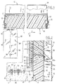
- la figure 1 est une vue partielle de face de la façade selon l'invention, depuis l'extérieur du bâtiment ;
- la figure 2 est une vue en coupe verticale, transversale à la façade, au niveau d'un premier organe de fixation ;
- la figure 3 est une vue de dessus du premier organe de fixation de la figure 2 et d'un premier élément de façade en coupe horizontale ;
- la figure 4 est une vue de face d'une deuxième organe de fixation reliés à un premier et à un deuxième éléments de façade ; et
- la figure 5 est une vue de dessus du deuxième organe de fixation de la figure 4 et des premier et deuxième éléments de façade en coupe horizontale.
- la figure 6 est une vue partielle avec arrachement d'un premier élément de façade, en coupe horizontale suivant un plan transversal perpendiculaire à ses grandes faces planes et à ses faces latérales destinées à s'étendre verticalement ;
- la figure 7 est une vue en coupe analogue à la figure 6 montrant la jonction entre un premier et un deuxième éléments de façade adjacents ; et
- la figure 8 est une vue à plus grande échelle d'un détail de la jonction.
Claims (15)
- Elément pour façade (8, 10), comportant un support et un panneau (25) comprenant au moins deux parties de fixation (68) fixées au support et une paroi (66) généralement plane s'étendant entre les deux parties de fixation (68), caractérisé en ce qu'au moins l'une des parties de fixation s'étend en retrait du plan de la paroi et est déformable de sorte que la paroi (25) est libre de se mouvoir parallèlement à elle-même par rapport au support lors d'une modification de la température du panneau.
- Elément pour façade selon la revendication 1, caractérisé en ce que le support comporte une âme (16) présentant au moins une face latérale (20) s'étendant suivant une direction générale perpendiculaire à la paroi (66) du panneau, le support comportant des moyens de fixation (22, 60) de la ou chaque partie de fixation s'étendant en regard et à distance de la face latérale (20) de l'âme.
- Elément pour façade selon la revendication 2, caractérisé en ce que les moyens de fixation sont reliés à une face arrière (17) de l'âme opposée à la paroi (66) du panneau.
- Elément pour façade selon la revendication 2 ou 3, caractérisé en ce que les moyens de fixation (22, 60) sont agencés pour recevoir la partie de fixation lors d'un déplacement relatif du support par rapport au panneau (25) perpendiculairement à la paroi (66).
- Elément pour façade selon la revendication 4, caractérisé en ce que le support comporte une surface de guidage (50a) adaptée à guider la partie de fixation (68) depuis une position voisine des moyens de fixation jusqu'à ceux-ci lors d'un déplacement relatif du support par rapport au panneau perpendiculairement à la paroi (66).
- Elément pour façade selon la revendication 5, caractérisé en ce que la surface de guidage (50a) est conformée pour éloigner les parties de fixation (68) l'une de l'autre lors du déplacement du support.
- Elément pour façade selon l'une quelconque des revendications 2 à 6, caractérisé en ce que le support comporte une première et une deuxième pièces d'assemblage (22, 60) constituant les moyens de fixation, la première pièce d'assemblage (22) étant fixée à l'âme (16) et s'étendant en regard de celle-ci et la deuxième pièce d'assemblage (60) s'étendant à l'extérieur de l'élément et étant fixée à la première pièce d'assemblage avec interposition d'un joint d'interposition (62) en matériau isolant thermique.
- Elément pour façade selon la revendication 7, caractérisé en ce que la première pièce d'assemblage (22) est profilée et s'étend le long d'une face latérale (20) de l'âme.
- Elément pour la construction d'une façade selon l'une quelconque des revendications 2 à 8, caractérisé en ce que l'âme (16) comprend un matériau alvéolaire.
- Elément pour la construction d'une façade selon l'une quelconque des revendications 1 à 9, caractérisé en ce que le panneau (25) comprend une matière plastique pleine.
- Ensemble pour la construction d'une façade caractérisé en ce qu'il comprend deux éléments de façade selon l'une quelconque des revendications 1 à 10 et un joint de liaison (74) adapté à être fixé aux deux éléments de façade lorsque ceux-ci sont disposés en étant adjacents l'un à l'autre, de façon à interdire le passage de l'air entre les deux éléments de façade suivant une direction perpendiculaire aux parois (66) des panneaux.
- Ensemble pour la construction d'une façade selon la revendication 11, caractérisé en ce que chaque élément de façade (8, 10) comporte un joint à recouvrement (72) agencé de sorte que les joints à recouvrement de deux éléments de façade disposés en étant adjacents l'un à l'autre viennent en contact l'un avec l'autre de manière à interdire des passages de projections d'eau entre les deux éléments de façade suivant une direction perpendiculaire aux parois (66) des panneaux.
- Ensemble pour la construction d'une façade selon les revendications 11 et 12, caractérisé en ce que la deuxième pièce d'assemblage (60) est adaptée à recevoir en fixation au moins l'un des joints parmi les joints de recouvrement (72) et de liaison (74).
- Façade caractérisée en ce qu'elle comporte un élément (8, 10) pour façade selon l'une quelconque des revendications 1 à 10.
- Façade caractérisée en ce qu'elle comporte un ensemble selon l'une quelconque des revendications 11 à 13.
Applications Claiming Priority (2)
| Application Number | Priority Date | Filing Date | Title |
|---|---|---|---|
| FR9612260A FR2754286B1 (fr) | 1996-10-08 | 1996-10-08 | Element pour facade avec parement decoratif |
| FR9612260 | 1996-10-08 |
Publications (1)
| Publication Number | Publication Date |
|---|---|
| EP0835966A1 true EP0835966A1 (fr) | 1998-04-15 |
Family
ID=9496469
Family Applications (1)
| Application Number | Title | Priority Date | Filing Date |
|---|---|---|---|
| EP97402338A Withdrawn EP0835966A1 (fr) | 1996-10-08 | 1997-10-06 | Elément pour façade avec parement décoratif |
Country Status (7)
| Country | Link |
|---|---|
| US (1) | US6339906B1 (fr) |
| EP (1) | EP0835966A1 (fr) |
| AU (1) | AU4560697A (fr) |
| BR (1) | BR9712222A (fr) |
| CA (1) | CA2268015A1 (fr) |
| FR (1) | FR2754286B1 (fr) |
| WO (1) | WO1998015699A1 (fr) |
Families Citing this family (2)
| Publication number | Priority date | Publication date | Assignee | Title |
|---|---|---|---|---|
| US6598359B1 (en) * | 1998-06-08 | 2003-07-29 | Heinrich Wulfert | Earthquake-immune curtain wall system |
| US6985516B1 (en) | 2000-11-27 | 2006-01-10 | Qualcomm Incorporated | Method and apparatus for processing a received signal in a communications system |
Citations (5)
| Publication number | Priority date | Publication date | Assignee | Title |
|---|---|---|---|---|
| FR1294119A (fr) * | 1960-07-20 | 1962-05-26 | Perfectionnements aux procédés de construction de bâtiments et panneaux préfabriqués obtenus par la mise en oeuvre de ce procédé | |
| EP0297192A1 (fr) * | 1986-06-27 | 1989-01-04 | Dätwyler France | Panneau de mur rideau à système d'étanchéité, système d'étanchéité, et profilé correspondant |
| EP0347159A2 (fr) * | 1988-06-13 | 1989-12-20 | Alcan International Limited | Structure à panneaux pour tandem de tôture |
| DE3903511A1 (de) * | 1989-02-06 | 1990-08-09 | Rheinhold & Mahla Gmbh | Ebenes bekleidungselement |
| EP0567087A1 (fr) * | 1992-04-23 | 1993-10-27 | Rolf Rand | Dispositif de fixation pour revêtements de façade |
Family Cites Families (9)
| Publication number | Priority date | Publication date | Assignee | Title |
|---|---|---|---|---|
| GB1459401A (en) * | 1973-01-10 | 1976-12-22 | Stoakes R L | Structural assemblies |
| BE825631A (fr) * | 1975-02-17 | 1975-06-16 | Structure de mur-rideau | |
| JPH0634990Y2 (ja) * | 1988-03-02 | 1994-09-14 | 吉田工業株式会社 | 石材パネルユニット |
| US4924647A (en) * | 1989-08-07 | 1990-05-15 | E. G. Smith Construction Products Inc. | Exterior wall panel drainage system |
| US5058344A (en) * | 1990-03-13 | 1991-10-22 | Butler Manufacturing Corporation | Wall panel system |
| US5263292A (en) * | 1991-01-07 | 1993-11-23 | American Wall Products | Building panel system |
| US5212914A (en) * | 1991-05-28 | 1993-05-25 | Alu Tech Systems, Inc. | Wall paneling system with water guttering device |
| EP0683287B1 (fr) * | 1994-05-16 | 1998-08-12 | Ul Tech Ag | Rail profilé de fixation d'objets plats |
| US5544461A (en) * | 1994-09-30 | 1996-08-13 | Sommerstein; Michael | Panel mounting structure |
-
1996
- 1996-10-08 FR FR9612260A patent/FR2754286B1/fr not_active Expired - Fee Related
-
1997
- 1997-10-06 EP EP97402338A patent/EP0835966A1/fr not_active Withdrawn
- 1997-10-06 CA CA002268015A patent/CA2268015A1/fr not_active Abandoned
- 1997-10-06 US US09/269,747 patent/US6339906B1/en not_active Expired - Fee Related
- 1997-10-06 BR BR9712222-0A patent/BR9712222A/pt not_active IP Right Cessation
- 1997-10-06 AU AU45606/97A patent/AU4560697A/en not_active Abandoned
- 1997-10-06 WO PCT/FR1997/001771 patent/WO1998015699A1/fr not_active Ceased
Patent Citations (5)
| Publication number | Priority date | Publication date | Assignee | Title |
|---|---|---|---|---|
| FR1294119A (fr) * | 1960-07-20 | 1962-05-26 | Perfectionnements aux procédés de construction de bâtiments et panneaux préfabriqués obtenus par la mise en oeuvre de ce procédé | |
| EP0297192A1 (fr) * | 1986-06-27 | 1989-01-04 | Dätwyler France | Panneau de mur rideau à système d'étanchéité, système d'étanchéité, et profilé correspondant |
| EP0347159A2 (fr) * | 1988-06-13 | 1989-12-20 | Alcan International Limited | Structure à panneaux pour tandem de tôture |
| DE3903511A1 (de) * | 1989-02-06 | 1990-08-09 | Rheinhold & Mahla Gmbh | Ebenes bekleidungselement |
| EP0567087A1 (fr) * | 1992-04-23 | 1993-10-27 | Rolf Rand | Dispositif de fixation pour revêtements de façade |
Also Published As
| Publication number | Publication date |
|---|---|
| AU4560697A (en) | 1998-05-05 |
| CA2268015A1 (fr) | 1998-04-16 |
| US6339906B1 (en) | 2002-01-22 |
| FR2754286A1 (fr) | 1998-04-10 |
| BR9712222A (pt) | 1999-11-09 |
| WO1998015699A1 (fr) | 1998-04-16 |
| FR2754286B1 (fr) | 1998-12-31 |
Similar Documents
| Publication | Publication Date | Title |
|---|---|---|
| EP2313574B1 (fr) | Moyens de cintrage de profil pour cadre a empocher | |
| CA1260211A (fr) | Corniche pour ouvrage d'art | |
| EP2497877A1 (fr) | Joint parasismique | |
| EP1783292B1 (fr) | Profil pour cadre de dalle de faux plafond, en particulier pour cadre à empocher | |
| FR2544766A1 (fr) | Panneau modulaire prefabrique d'isolation thermique par l'exterieur, procedes pour sa fabrication et dispositif pour sa fixation | |
| CA2268015A1 (fr) | Element pour facade avec parement decoratif | |
| FR2553454A1 (fr) | Dispositif de revetement pour murs, sols, meubles et applications analogues | |
| FR2692541A1 (fr) | Véhicule ferroviaire formé par assemblage modulaire. | |
| EP0136954B1 (fr) | Procédé pour l'utilisation de feuilles de stratifié pour la constitution de parois internes d'habitations, de décors, d'éléments d'ameublement et similaires | |
| EP0414654A1 (fr) | Panneau intérieur de façade légère ventilée | |
| EP0835967A1 (fr) | Façade de bâtiment comprenant des éléments de poids réduits | |
| EP0701646B1 (fr) | Profile pour un panneau mur porteur sandwich, panneau avec un tel profile et construction avec un tel panneau | |
| FR2478165A1 (fr) | Procede et dispositifs pour construire un mur isolant | |
| FR2733263A1 (fr) | Panneau composite, assemblage de panneaux et batiment de type prefabrique construit a l'aide de tels panneaux | |
| EP0431230A1 (fr) | Dispositif de fixation de panneaux vitrés dans une façade de bâtiment du type façade rideau | |
| FR2540165A1 (fr) | Dispositif de fixation pour elements de construction rapportes formant facade et procede de montage de ces elements | |
| BE834999A (fr) | Element de facade et elements de fixation a la structure d'un batiment | |
| FR2763352A1 (fr) | Systeme de montage d'un revetement constitue de panneaux juxtaposes pour former un parement de facade de batiment | |
| FR2799489A1 (fr) | Element de cloture en metal ou en matiere plastique | |
| FR2585048A1 (fr) | Construction prefabriquee | |
| FR2725744A1 (fr) | Garde-corps pour balcon a profil courbe | |
| FR2727142A1 (fr) | Structure de facade pour immeuble ou construction analogue | |
| BE841345R (fr) | Element de facade | |
| CH524032A (fr) | Panneau pour la construction de murs et cloisons | |
| FR2554846A1 (fr) | Module pour la construction d'une paroi de batiment |
Legal Events
| Date | Code | Title | Description |
|---|---|---|---|
| PUAI | Public reference made under article 153(3) epc to a published international application that has entered the european phase |
Free format text: ORIGINAL CODE: 0009012 |
|
| AK | Designated contracting states |
Kind code of ref document: A1 Designated state(s): AT BE CH DE DK ES FI FR GB GR IE IT LI LU MC NL PT SE |
|
| AX | Request for extension of the european patent |
Free format text: AL;LT;LV;RO;SI |
|
| 17P | Request for examination filed |
Effective date: 19981012 |
|
| AKX | Designation fees paid |
Free format text: AT BE CH DE DK ES FI FR GB GR IE IT LI LU MC NL PT SE |
|
| RBV | Designated contracting states (corrected) |
Designated state(s): AT BE CH DE DK ES FI FR GB GR IE IT LI LU MC NL PT SE |
|
| RAP1 | Party data changed (applicant data changed or rights of an application transferred) |
Owner name: ATOFINA Owner name: MONOPANEL S.A. |
|
| 17Q | First examination report despatched |
Effective date: 20010503 |
|
| GRAP | Despatch of communication of intention to grant a patent |
Free format text: ORIGINAL CODE: EPIDOSNIGR1 |
|
| STAA | Information on the status of an ep patent application or granted ep patent |
Free format text: STATUS: THE APPLICATION IS DEEMED TO BE WITHDRAWN |
|
| 18D | Application deemed to be withdrawn |
Effective date: 20040225 |