EP0836000B1 - Klappenschubumkehrvorrichtung mit geregeltem Leckstrom - Google Patents
Klappenschubumkehrvorrichtung mit geregeltem Leckstrom Download PDFInfo
- Publication number
- EP0836000B1 EP0836000B1 EP97402376A EP97402376A EP0836000B1 EP 0836000 B1 EP0836000 B1 EP 0836000B1 EP 97402376 A EP97402376 A EP 97402376A EP 97402376 A EP97402376 A EP 97402376A EP 0836000 B1 EP0836000 B1 EP 0836000B1
- Authority
- EP
- European Patent Office
- Prior art keywords
- door
- downstream
- flow
- thrust reverser
- jet mode
- Prior art date
- Legal status (The legal status is an assumption and is not a legal conclusion. Google has not performed a legal analysis and makes no representation as to the accuracy of the status listed.)
- Expired - Lifetime
Links
- 238000011144 upstream manufacturing Methods 0.000 claims description 18
- 230000000694 effects Effects 0.000 claims description 10
- 238000005192 partition Methods 0.000 claims 9
- 230000000903 blocking effect Effects 0.000 claims 3
- 238000001816 cooling Methods 0.000 description 2
- 210000003462 vein Anatomy 0.000 description 2
- 238000000429 assembly Methods 0.000 description 1
- 230000000712 assembly Effects 0.000 description 1
- 238000010790 dilution Methods 0.000 description 1
- 239000012895 dilution Substances 0.000 description 1
- 238000006073 displacement reaction Methods 0.000 description 1
- 238000009434 installation Methods 0.000 description 1
- 230000000750 progressive effect Effects 0.000 description 1
- 238000002407 reforming Methods 0.000 description 1
- 238000007789 sealing Methods 0.000 description 1
- 238000000926 separation method Methods 0.000 description 1
- 230000003068 static effect Effects 0.000 description 1
- 238000009966 trimming Methods 0.000 description 1
Images






Classifications
-
- F—MECHANICAL ENGINEERING; LIGHTING; HEATING; WEAPONS; BLASTING
- F02—COMBUSTION ENGINES; HOT-GAS OR COMBUSTION-PRODUCT ENGINE PLANTS
- F02K—JET-PROPULSION PLANTS
- F02K1/00—Plants characterised by the form or arrangement of the jet pipe or nozzle; Jet pipes or nozzles peculiar thereto
- F02K1/54—Nozzles having means for reversing jet thrust
- F02K1/74—Reversing at least one flow in relation to at least one other flow in a plural- flow engine
-
- F—MECHANICAL ENGINEERING; LIGHTING; HEATING; WEAPONS; BLASTING
- F02—COMBUSTION ENGINES; HOT-GAS OR COMBUSTION-PRODUCT ENGINE PLANTS
- F02K—JET-PROPULSION PLANTS
- F02K1/00—Plants characterised by the form or arrangement of the jet pipe or nozzle; Jet pipes or nozzles peculiar thereto
- F02K1/54—Nozzles having means for reversing jet thrust
- F02K1/64—Reversing fan flow
- F02K1/70—Reversing fan flow using thrust reverser flaps or doors mounted on the fan housing
Definitions
- outer casing the assembly constituted by the outer wall of the nacelle
- the reversing device consists of doors 2 forming a movable part and constituting in the inactive position, when direct jet operation, part of the enclosure exterior, and of a fixed structure carrying out this rollover outside upstream of the doors, through an upstream part 1 and downstream of the doors by a downstream part 3 and between the doors 2 by means of beams which connect the downstream part 3 from the outer casing to the upstream part of the casing outside.
- Doors 2 are mounted on a circumference of the outer casing and are pivotally mounted in an area intermediate their side walls on the beams located on either side of these doors, these walls side constituting with the upstream and downstream walls, the walls which connect the outer part 4 of the doors 2, which constitute a part of the external wall of the nacelle, to the interior part 5 of the doors 2, which constitute a part of the outer wall of the duct.
- the upstream part 1 of fixed structure comprises a front frame which serves as a support for the movement control means doors 2, constituted for example by jacks 8.
- the doors 2 tilt so that the part of the doors located downstream of the pivots 20 obstructs the duct more or less completely, and so that the upstream part of the doors clears a passage in the outer casing so as to allow the secondary flow to be channeled radially with respect to the axis of the conduit.
- the upstream part of the doors 2 protrudes outside the outer cowling for reasons of dimensioning the passage which must be capable of letting this flow pass without compromising the operation of the engine.
- the pivot angle of the doors is adjusted so as to allow the passage of the flow and so as to suppress the thrust of this flow, or even begin to generate a counter-thrust by generating a component of the flow deflected upstream.
- EP-A-0 368 725 describes a thrust reverser in which a pivoting door has an internal passage formed between the internal panel and the external door panel, having an opening at each end so as to create a separation of the flow inverted and a movable flap can be added to the opening downstream of the passage.
- the doors tilt so that the part located downstream of the pivots more or less completely obstructs the duct during the reverse jet phase.
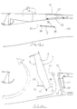
- a door 2 the external wall 4 of which constitutes, in the direct jet position, part of the external envelope of the nacelle, its internal wall 5 constituting a part of the external vein wall of the annular channel 15 forming the flow conduit comprises in its downstream part a movable flap 10 articulated around a pivot axis 11 integral with said door.
- the downstream structure of the door 2 comprises an orifice 12 located between the two webs 13 and 14, the upstream web 14 being able to constitute the downstream end of the structural part of the door connecting the external wall 4 to the inner wall 5, while the downstream web 13 has the main function of deflecting and controlling the leakage rate 17 in the reverse jet position.
- the position of the movable flap 10 is such that its external profile 18 located in the duct 15 ensures the continuity of the internal profile 5 of the door 2 while completely obstructing the orifice 12, the sealing being ensured by a seal which can be of the O-ring type, situated all around the periphery of the orifice 12 either on the movable flap 10 or on the door 2.
- the continuity of the nacelle outer envelope is ensured by a flange 3a of the fixed structure downstream 3 of the inverter which closes the orifice 12.
- the shutter 10 is maneuvered by means of at least one control rod 21, one of its ends of which is secured to the operating element 8 of the door 2 at a pivot point 7, the other end being secured to the movable flap 10 at point 9.
- most of the flow 6 is deflected by the internal profile 5 of the door 2, while the movable flap 10 pivoting about its axis 11, releases the orifice 12, thus allowing the passage of a leakage flow 17 between the webs 14 and 13, the latter deflecting the flow 17 in a defined direction making it possible to suppress the residual thrust.
- each door can be equipped with one or more movable flaps 10, located opposite one or more openings made in the internal wall of said door. The installation of the shutters and the corresponding openings can be carried out symmetrically or not with respect to the center axis of the door, over all or part of its width.
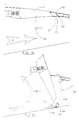
- a door 2 is equipped in its downstream part with one or more orifice (s) 12 obstructed (s) in direct jet position by a movable flap 23 articulated around an axis 22 secured to the door 2 in its downstream part between two longitudinal webs 16.
- An adjustable stop 24 secured to the downstream part 3 of the fixed structure, ensures, during the closing of the door 2, the closing of the part 23.
- a fixed or adjustable stop 25 guarantees the optimal position of the flap 23 in reverse jet.
- a system for assisting in opening or closing such as a torsion spring mounted on the axis 22, can be associated with the flap 23 in order to facilitate its opening from the start of the reverse jet phase. , or its reclosing or its progressive controlled opening according to the value of the static pressure at the bottom of the door.
- FIGS 7 and 8 show a possible alternative embodiment in which the orifice 12 of the internal panel of the door 2 located in the downstream part between the sails 14 and 13, is obstructed in direct jet phase by a fairing 28 ensuring continuity of the external profile of the annular channel 15, the contour of said fairing being suitable for trimming the orifice 12.
- Each fairing 28 is connected to the rear body of the fixed structure by means of one or more supports 27.
- flap 23 is such that during the jet inversion phase, its downstream end 23a in bearing on the external profile of the primary cover 64, the drive in rotation about the axis 22 thus releasing the passage 12.
- deflector 13 a veil 13a which releases during the opening of the door the opening 3b made in the rim 3a of the fixed structure 3, and ensures in direct jet position the continuity of the latter's external profile.
- Part 23 can also be ordered by any other known means of the skilled person, so as to rotate it around axis 22 when opening door 2.
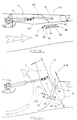
- a downstream panel 29 is rotated upstream about a pivot axis 36 by means of at least one lateral connecting rod 31 secured to the door at point 34 and connected to the downstream panel 29 at point 35.
- the internal panel 5 of the door 2 is limited in its downstream part by the wall 14 so that , that in the reverse jet position a leakage flow 17 can flow between the wall 14 and the internal profile of the annular channel.
- Downstream of the wall 14 can be installed, in the longitudinal direction, several sails 32 parallel or not to each other in a converging or diverging position symmetrically or not with respect to the center axis of the door 2, depending on the aerodynamic effects sought in reverse jet phase.
- one or more longitudinal sails 37 of profile and orientation suitable for the desired effects can be installed between the sails 32.
- the position of the points 34 and 35 as well as the length of the rod 31, are parameters such that they define a kinematics positioning the downstream panel 29 in reverse jet mode, so that its upstream end is close to, or even in contact with, with the internal profile of the annular channel 15, and following, an orientation ensuring the deflection of the leakage flow 17 by the external profile 30 of said downstream panel.
- the kinematics thus defined positions the downstream panel 29 in such a way that it seals both with the door 2 and with the downstream structure 3 and that the internal profile 26 ensures the continuity of the external profile of the annular channel.
- Figures 11 and 12 show a possible variant of the embodiment of the invention described above according to which a part 41 of the cowling 40 of the rear body 3 is connected to the downstream panel 29 by means of one or more sails 42 thus improving the control of the leakage flow 17 during the reverse jet phase, allowing at the same time its evacuation directly through the opening 44 resulting from the tilting of the cover 41.
- a suitable shape of the internal face 30 of the panel makes it possible to orient the flow 17 in a defined direction making it possible to suppress the residual thrust, or even to generate an additional counter-thrust.
- 13 and 14 represent another possible variant of the embodiment of the invention described above in which, the parameters defining the drive kinematics of the downstream panel 29 are such that the rotation of the panel takes place downstream, so that in the reverse jet position, the annular channel 15 is closed off by the downstream end of the downstream panel 29.
- the leakage flow 17 is channeled towards the outside of the nacelle between the outer wall 4 of the door 2 and the inner wall 37 of the downstream panel 29.
- the pivot axis of the panel can be fixed as in the example shown, or mobile (linked to the door) as described in French patent n ° 2,741,910 in which the leakage flow 17 could be channeled, in the reverse jet position, between the downstream end of the door and the upstream end of the downstream panel.
- a relatively cold air suction phenomenon 50 coming from the downstream end of the nacelle by a passage made through the panel between the sails 42 as required, can be generated by effect of entrainment by the flow 17, and can induce a slight depression of the annular channel 15 during the reverse jet phase downstream of the doors.
- This flow 50 can be used as a function of the aerodynamic effects sought, to promote the evacuation and / or cooling of the leakage flow 17 to generate an additional counter-thrust and / or improve the cooling of the rear part of the engine hood 64 by l flow 50.
- Figures 23 and 24 show another variant of the embodiment of the invention associated with a downstream panel 81, the latter having no fixed pivot relative to the fixed structure of the inverter.
- an example of kinematics guaranteeing the movement of the panel 81 consists of a control rod 83, one of its ends of which is integral with the operating element 8 of the door 2 in one pivot point 90, the other end being secured to the downstream panel 81 at point 91, and a parallelogram consisting of at least one pair of connecting rods 84 and 85 respectively secured to the door 2 at points 88 and 89, and to the panel downstream 81 at points 87 and 86.
- Other kinematics known to those skilled in the art can be envisaged for the operation of the downstream panel 81.
- the movable downstream panel 81 may include in its upstream part, at its external profile, a casing 81a, the aim of which is to improve the control of the leakage flow 17, and ensuring the continuity of the external profile of the door 2 when the latter has a cutout in its external profile allowing the movement of the control rod 83.
- Figures 15 and 16 show a third embodiment of the invention associated with an inverter equipped with doors whose downstream end 60 of said doors also constitutes the downstream end of the inverter, a particular configuration that can be encountered for example in the case of an inverter with a very high dilution rate.
- the door 2 has at its external profile 4, a cavity 54 allowing the housing of a movable flap 51 articulated around a pivot axis 53 generally located close to the axis of rotation 20 of the door 2 in the side beams of the fixed structure of the inverter.
- a cavity 54 allowing the housing of a movable flap 51 articulated around a pivot axis 53 generally located close to the axis of rotation 20 of the door 2 in the side beams of the fixed structure of the inverter.
- the position of points 20, 53, 56 and 57, as well as the length of the connecting rod 52, are parameters such that they define a kinematics positioning the movable flap 51 in reverse jet mode, so that its downstream end 60 is found close to or even in contact with the internal profile of the primary cover 64, and sufficiently distant downstream from the downstream end 61 of the door 2, so as to allow the evacuation of a leakage flow 17, channeled by the profile internal 58 and the spoiler 55 of the movable flap 51.
- Figures 15 and 16 show that the axis of rotation of the movable flap 51 is different from the axis of rotation 20 of the door 2, but one can consider a common axis of rotation for these two elements, the movement of the flap 51 being in this case provided by a parallelogram type system.
- FIGS. 17 and 18 represent a fourth embodiment of the invention, characterized by an operation independent or not of the door opening kinematics, the latter being equipped with two movable flaps, the first 72 located at the level of the external profile 4 and connected to the door at the level of the axis 71, the second 76 located at the level of the internal profile 5 and connected to the door at the level of the axis 77.
- a cylinder 70 is installed, the commissioning of which causes rotation towards the interior of the door, the flaps 72 and 76 respectively around the axes 71 and 77 via the connecting rods 79 and 78.
- the connecting rod 79 is secured to the jack 70 at point 80 and to the flap 72 at point 73, the connecting rod 78 being secured to the jack 70 at point 80 and in section 76 in point 75.
- the position of the flaps 72 and 76, adjustable as a function of the stroke of the jack 70, is such that they release respectively at the external profile 4 of the door 2 as well as at the internal profile 5, a passage and qu 'They are positioned so as to form downstream of the wall 74 and with the help of the latter a discharge conduit allowing the flow of a leakage flow 17. It should be noted that, depending on the geometry of the door and the aerodynamic effects sought, several assemblies consisting of a jack 70, flaps 72 and 76 and connecting rods 79 and 78, can be installed in places judiciously chosen so as to to obtain an optimal effect.
- the actuation of the jack 70 can be done at any time during the jet inversion phase, or even before the opening of the door begins.
- the flaps 72 and 76 can be subjected to the opening of the door by suitable kinematics, not involving additional cylinders.
- the opening made in the door can be located at any point of the door.
- the flow 17 can be evacuated from a zone located higher on the door, for example in the break or in the cavity.
- the mobile structure 65 comprises in its downstream part, a cowling 68 ensuring in the direct jet position the continuity of the downstream end of the external part of the nacelle, as shown in Figures 26 and 27.
- Figure 25 shows in reverse jet position, another embodiment of the invention, characterized in that that the leakage flow 17 authorized between all or part of the downstream end of the door 2 and the primary cover 64, found deflected by one or more air jets 67 sampled at primary flow level, or other high compressed air source available pressure.
- the flow rate of each air jet 17, as well that their longitudinal and radial location are defined to obtain an optimal deflection of the leakage flow 17.
- the invention can be applied to a inverter with grids and in particular to the shutter panels of the reverse jet flow.
Landscapes
- Engineering & Computer Science (AREA)
- Chemical & Material Sciences (AREA)
- Combustion & Propulsion (AREA)
- Mechanical Engineering (AREA)
- General Engineering & Computer Science (AREA)
- Structures Of Non-Positive Displacement Pumps (AREA)
- Control Of Turbines (AREA)
- Superstructure Of Vehicle (AREA)
Claims (19)
- Schubumkehrvorrichtung für Zweikreis-TL-Triebwerk mit Schwenkklappen (2), die sich in Schließstellung im Direktstrahlbetrieb in die Außenwand der Strömungsleitung hinter dem Turbotriebwerks-Gebläse einfügen und aus einem äußeren Teil (4) und einem inneren Teil (5) bestehen, wobei sie ferner alle bei Umkehrschubbetrieb unter der Einwirkung eines Bewegungs-Steuermittels wie z. B. eines Zylinders (8) um Drehachsen (20) schwenken, die an dem festen Aufbau der Schubumkehrvorrichtung sitzen, so dass sie Stromumlenkhindernisse bilden,
dadurch gekennzeichnet, dass mindestens eine Klappe (2) im hinteren Bereich einen Durchgang (12) enthält, der den inneren Teil (5) und den äußeren Teil (4) der Klappe vollständig durchquert und dessen Geometrie dergestalt ausgeführt ist, dass bei Umkehrschubbetrieb hinter und außerhalb der Klappe (2) ein Leckstrom (17) in gesteuerter Menge und gesteuerter Richtung ermöglicht wird, wobei Mittel (10) diesen Durchgang (12) im Direktstrahlbetrieb verschließen, so dass die Kontinuität der radial äußeren Fläche (18) der Strömungsleitung (15) gewährleistet ist. - Schubumkehrvorrichtung für Zweikreis-TL-Triebwerk nach Anspruch 1, bei der der innere Teil der Klappe hinten eine bewegliche Klappe (10; 23) aufweist, die um eine mit der Klappe (2) fest verbundene Drehachse (11; 22) schwenkbar angelenkt ist, im Direktstrahlbetrieb die Kontinuität der radial äußeren Fläche (18) der Strömungsleitung (15) gewährleistet und in Umkehrschubstellung einen Durchgang freigibt, der aus einer Öffnung (12) besteht, die im hinteren Bereich dieser Klappe (2) ausgeführt ist und einen Teil des sogenannten Leckstroms (17) durchlässt, wobei eine Randleiste (3a), die mit dem hinteren festen Aufbau (3) der Schubumkehrvorrichtung fest verbunden ist, ferner im Direktstrahlbetrieb diese Öffnung (12) verschließt, so dass die Kontinuität des Außenmantels der Gondel gewährleistet ist.
- Schubumkehrvorrichtung für Zweikreis-TL-Triebwerk nach Anspruch 2, bei der diese bewegliche Klappe (10) mit einem Deflektor (19) versehen ist, der diesen Leckstrom (17) im Schubumkehrbetrieb zu der Öffnung (12) führt.
- Schubumkehrvorrichtung für Zweikreis-TL-Triebwerk nach einem der Ansprüche 2 oder 3, bei der diese bewegliche Klappe (10) durch mindestens eine Stange (21) mit dem Steuerzylinder (8) der Klappe (2) verbunden ist.
- Schubumkehrvorrichtung für Zweikreis-TL-Triebwerk nach einem der Ansprüche 2 bis 4, bei der die genannte Öffnung (12) von einer vorderen Blende (14) beschränkt wird, die das Ende des hinteren Aufbauteils der Klappe (2) bildet, sowie von einer hinteren Blende (13) beschränkt wird, die in Zusammenwirkung mit mindestens zwei seitlichen, in Längsrichtung angeordneten Blenden (16) die Umlenkung und Führung des Leckstroms (17) gewährleistet, so dass der Restschub in dem hinteren Teil der Strömungsleitung verringert oder beseitigt wird.
- Schubumkehrvorrichtung für Zweikreis-TL-Triebwerk nach Anspruch 2, bei der diese bewegliche Klappe (23) im Schubumkehrbetrieb unter der Einwirkung des Drucks der Strömung geöffnet wird, wobei sie den Durchgang durch die Öffnung (12) freigibt, und im Direktstrahlbetrieb durch ein Anschlagmittel (24), das mit dem hinteren festen Aufbau (3) der Schubumkehrvorrichtung fest verbunden ist, festgehalten wird, wobei sie diese Öffnung (12) verschließt.
- Schubumkehrvorrichtung für Zweikreis-TL-Triebwerk nach Anspruch 1, bei der dieser Durchgang aus mindestens einer Öffnung (12) besteht, die von einer vorderen Blende (14) beschränkt wird, die das Ende des hinteren Aufbauteils der Klappe (2) bildet, sowie von einer hinteren Blende (13) beschränkt wird, wobei diese Öffnung (12) im Direktstrahlbetrieb von einer Verkleidung (28) verschlossen wird, die durch mindestens einen Träger (27) mit dem hinteren festen Aufbau (3) der Schubumkehrvorrichtung verbunden ist.
- Schubumkehrvorrichtung für Zweikreis-TL-Triebwerk nach Anspruch 1, die ferner eine Platte (29) aufweist, die mit jeder Klappe (2) verbunden ist, hinter dieser Klappe angeordnet ist, von einem Drehzapfen (36) getragen wird, der an dem festen Aufbau der Schubumkehrvorrichtung sitzt, und mit dieser Klappe (2) durch ein angelenktes mechanisches Mittel wie z. B. eine Stange (31) verbunden ist, wobei dieser Durchgang im Schubumkehrbetrieb zwischen einer hinteren Wand (14), die das Ende des hinteren Aufbauteils der Klappe (2) bildet, und der radial inneren Wand (64) der Strömungsleitung (15) ausgeführt ist, so dass der Leckstrom von dieser hinteren Platte (29) umgelenkt wird.
- Schubumkehrvorrichtung für Zweikreis-TL-Triebwerk nach Anspruch 8, bei der ein Teil (41) der Außenverkleidung an der hinteren Platte (29) durch mindestens eine Blende (42) fest angebracht wird, so dass im Schubumkehrbetrieb eine Auslassöffnung (44) für den Leckstrom freigegeben wird.
- Schubumkehrvorrichtung für Zweikreis-TL-Triebwerk nach Anspruch 9, bei der die Positionen des Drehzapfens (36) und der Verbindungsstange (31) der hinteren Platte (29) dergestalt bestimmt sind, dass die hintere Platte (29) die der Umkehrschubstellung entsprechende Position durch Drehung nach hinten einnimmt, so dass eine Führung des Leckstroms (17) durch die innere Wand (37) der hinteren Platte (29) gewährleistet ist, sowie ein Ansaugen des hinteren Mantelsttoms (50), der in dem äußeren Teil der hinteren Platte (29) zirkuliert, um durch die äußere Öffnung (44) gleichzeitig mit dem Leckstrom (17) ausgelassen zu werden.
- Schubumkehrvorrichtung für Zweikreis-TL-Triebwerk nach Anspruch 1, bei der jede Klappe (2) einen Hohlraum (54) enthält, der an ihrer radial äußeren Seite ausgeführt ist und in den im Direktstrahlbetrieb eine bewegliche Klappe (51) placiert wird, die die Kontinuität der Außenfläche der Gondel in der Verlängerung des äußeren Klappenteils (4) gewährleistet und das hintere Ende der Schubumkehrvorrichtung sowie den hinteren Teil der radial äußeren Wand der Strömungsleitung (15) bildet, während dieser Durchgang im Schubumkehrbetrieb zwischen der Klappe (2) und der genannten Klappe (51) gebildet wird, die die Führung des Leckstroms (17) nach Schwenken um eine an dem festen Aufbau der Schubumkehrvorrichtung sitzende Drehachse (53) unter Einwirkung einer Verbindungsstange (52) zu der Klappe (2) gewährleistet.
- Schubumkehrvorrichtung für Zweikreis-TL-Triebwerk nach Anspruch 1, bei der der äußere Teil (4) der Klappe (2) hinten eine erste bewegliche Klappe (72) aufweist, die um eine mit dieser Klappe (2) fest verbundene Drehachse (71) angelenkt ist, und bei der der innere Teil (5) der Klappe (2) hinten eine zweite bewegliche Klappe (76) aufweist, die um eine mit dieser Klappe (2) fest verbundene Drehachse (77) angelenkt ist, wobei die erste Klappe (72) und die zweite Klappe (76) geeignet sind, unter der Einwirkung eines unabhängigen Zylinders (70), der im Inneren der Klappe (2) eingebaut ist, in der Klappe (2) den genannten Durchlass zu öffnen, der von diesen Klappen (72, 76) vorne und von einer hinten zwischen der inneren Fläch (5) und der äußeren Fläche (4) der Klappe (2) angeordneten Wand (74) begrenzt wird, so dass der Leckstrom (17) im Schubumkehrbetrieb durchgelassen wird.
- Schubumkehrvorrichtung für Zweikreis-TL-Triebwerk nach Anspruch 2, bei der die genannte bewegliche Klappe (23) beim Öffnungsvorgang der Klappe (2) mit ihrem hinteren Ende (23a) an dem Außenprofil des Hauptmantels (64) des Turbotriebwerks dergestalt in Anlage kommt, dass sie um ihre Achse (22) schwenkt und dabei den Durchgang (12) freigibt.
- Schubumkehrvorrichtung für Zweikreis-TL-Triebwerk nach einem der Ansprüche 2 oder 13, bei der diese Öffnung (12) von einer hinteren Blende (13) beschränkt wird, auf der eine Blende (13a) sitzt, die beim Öffnen der Klappe (2) eine Öffnung (3b) freigibt, die in der Randleiste (3a) des hinteren festen Aufbaus (3) ausgeführt ist, und die diese Öffnung (3b) im Direktstrahlbetrieb überdeckt.
- Schubumkehrvorrichtung für Zweikreis-TL-Triebwerk nach Anspruch 1, die ferner in Verbindung mit jeder Klappe (2) eine Platte (81) aufweist, die hinter der Klappe (2) angeordnet ist, von einem Parallelogramm gehalten wird, das mindestens aus einem Paar Stangen (84, 85) besteht, die diese Platte (81) mit der Klappe (2) verbinden, und durch eine Stange (83) dergestalt mit dem Steuerzylinder (8) der Klappe (2) verbunden ist, dass der genannte Durchgang im Schubumkehrbetrieb zwischen einer hinteren Endblende (14) der Klappe (2) und der radial inneren Wand (64) der Strömungsleitung (15) ausgeführt ist, wobei der Leckstrom von dieser hinteren Platte (81) umgelenkt wird.
- Schubumkehrvorrichtung für Zweikreis-TL-Triebwerk nach Anspruch 1, bei der jede Klappe (2) an ihrem hinteren Ende einen beweglichen Aufbau (65) aufweist, der beim Öffnen dieser Klappe (2) in Vorschubbewegung zu der Klappe verschoben wird.
- Schubumkehrvorrichtung für Zweikreis-TL-Triebwerk nach Anspruch 16, bei der dieser bewegliche Aufbau (65) mindestens eine Umlenkschaufel trägt, die sich beim Öffnen der Klappe (2) in diesen Durchgang schiebt.
- Schubumkehrvorrichtung für Zweikreis-TL-Triebwerk nach einem der Ansprüche 16 oder 17, bei der dieser bewegliche Aufbau (65) in seinem hinteren Teil eine Verkleidung (68) aufweist, die im Direktstrahlbetrieb die Kontinuität der Außenlinie der Gondel gewährleistet.
- Schubumkehrvorrichtung für Zweikreis-TL-Triebwerk nach Anspruch 1, bei der aus einer Vielzahl von Luftstrahlen (67), die aus dem Primärstrom des Turbotriebwerks entnommen wurden, im Schubumkehrbetrieb dieser Leckstrom (17) wird.
Applications Claiming Priority (2)
| Application Number | Priority Date | Filing Date | Title |
|---|---|---|---|
| FR9612354A FR2754565B1 (fr) | 1996-10-10 | 1996-10-10 | Inverseur de poussee a portes a debit de fuite controle |
| FR9612354 | 1996-10-10 |
Publications (2)
| Publication Number | Publication Date |
|---|---|
| EP0836000A1 EP0836000A1 (de) | 1998-04-15 |
| EP0836000B1 true EP0836000B1 (de) | 2004-04-14 |
Family
ID=9496533
Family Applications (1)
| Application Number | Title | Priority Date | Filing Date |
|---|---|---|---|
| EP97402376A Expired - Lifetime EP0836000B1 (de) | 1996-10-10 | 1997-10-09 | Klappenschubumkehrvorrichtung mit geregeltem Leckstrom |
Country Status (8)
| Country | Link |
|---|---|
| US (1) | US5937636A (de) |
| EP (1) | EP0836000B1 (de) |
| JP (1) | JPH10122046A (de) |
| CA (1) | CA2218449A1 (de) |
| DE (1) | DE69728621D1 (de) |
| FR (1) | FR2754565B1 (de) |
| RU (1) | RU2156872C2 (de) |
| WO (1) | WO1998015731A1 (de) |
Families Citing this family (26)
| Publication number | Priority date | Publication date | Assignee | Title |
|---|---|---|---|---|
| FR2764339B1 (fr) * | 1997-06-05 | 1999-07-16 | Hispano Suiza Sa | Inverseur de poussee de turboreacteur a portes formant ecopes associees a une casquette amont mobile |
| FR2774431B1 (fr) * | 1998-02-04 | 2000-03-03 | Hispano Suiza Sa | Inverseur de poussee de turboreacteur a obstacles aval |
| RU2215168C2 (ru) * | 2001-10-25 | 2003-10-27 | Открытое акционерное общество "Авиадвигатель" | Реверсивное устройство наружного контура газотурбинного двигателя |
| FR2887854B1 (fr) * | 2005-06-30 | 2008-08-08 | Airbus France Sas | Nacelle pour aeronef et aeronef muni d'au moins une telle nacelle |
| FR2900980B1 (fr) * | 2006-05-10 | 2011-08-19 | Aircelle Sa | Nacelle pour turboreacteur double flux a grand taux de dilution |
| US8015797B2 (en) | 2006-09-21 | 2011-09-13 | Jean-Pierre Lair | Thrust reverser nozzle for a turbofan gas turbine engine |
| US8127529B2 (en) * | 2007-03-29 | 2012-03-06 | United Technologies Corporation | Variable area fan nozzle and thrust reverser |
| US8091827B2 (en) | 2007-11-16 | 2012-01-10 | The Nordam Group, Inc. | Thrust reverser door |
| US8002217B2 (en) * | 2007-11-16 | 2011-08-23 | Spirit Aerosystems, Inc. | System for adjustment of thrust reverser pivot door |
| US8052085B2 (en) | 2007-11-16 | 2011-11-08 | The Nordam Group, Inc. | Thrust reverser for a turbofan gas turbine engine |
| US7735778B2 (en) * | 2007-11-16 | 2010-06-15 | Pratt & Whitney Canada Corp. | Pivoting fairings for a thrust reverser |
| US8172175B2 (en) | 2007-11-16 | 2012-05-08 | The Nordam Group, Inc. | Pivoting door thrust reverser for a turbofan gas turbine engine |
| US8052086B2 (en) | 2007-11-16 | 2011-11-08 | The Nordam Group, Inc. | Thrust reverser door |
| US8051639B2 (en) | 2007-11-16 | 2011-11-08 | The Nordam Group, Inc. | Thrust reverser |
| FR2946696B1 (fr) * | 2009-06-10 | 2012-04-20 | Aircelle Sa | Dispositif d'inversion de poussee |
| FR2965304B1 (fr) * | 2010-09-23 | 2012-10-12 | Airbus Operations Sas | Dispositif de decharge d'air pour turboreacteur d'avion a double flux |
| FR2980825B1 (fr) | 2011-09-29 | 2013-09-13 | Aircelle Sa | Porte d'inverseur de poussee a ouvertures laterales |
| FR2982324B1 (fr) | 2011-11-09 | 2013-11-15 | Aircelle Sa | Inverseur de poussee a portes jumelles |
| FR2985782B1 (fr) * | 2012-01-17 | 2015-07-24 | Aircelle Sa | Inverseur de poussee a portes jumelles |
| UA103413C2 (en) * | 2012-03-30 | 2013-10-10 | Владимир Иосифович Белоус | Gas-turbine engine |
| US9784214B2 (en) * | 2014-11-06 | 2017-10-10 | Rohr, Inc. | Thrust reverser with hidden linkage blocker doors |
| DE102015206985A1 (de) * | 2015-04-17 | 2016-10-20 | Rolls-Royce Deutschland Ltd & Co Kg | Triebwerksverkleidung einer Fluggasturbine |
| US20170122255A1 (en) * | 2015-10-28 | 2017-05-04 | Pratt & Whitney Canada Corp. | Chevron system for gas turbine engine |
| US20170198658A1 (en) * | 2016-01-11 | 2017-07-13 | The Boeing Company | Thrust reverser |
| EP3534038B1 (de) | 2018-03-01 | 2023-05-03 | Goodrich Actuation Systems Limited | Aktuator mit doppelter stange und exzenterkupplung |
| FR3082889A1 (fr) * | 2018-06-26 | 2019-12-27 | Airbus Operations | Turboreacteur comportant une nacelle equipee de volets inverseurs pourvus de moyens pour generer des tourbillons |
Family Cites Families (17)
| Publication number | Priority date | Publication date | Assignee | Title |
|---|---|---|---|---|
| US2847823A (en) * | 1955-03-15 | 1958-08-19 | Curtiss Wright Corp | Reverse thrust nozzle construction |
| US3279182A (en) * | 1965-06-07 | 1966-10-18 | Gen Electric | Thrust reverser |
| FR1482538A (fr) * | 1965-06-07 | 1967-05-26 | Gen Electric | Inverseur de poussée |
| GB1181746A (en) * | 1968-06-19 | 1970-02-18 | Rolls Royce | Thrust Reverser for Jet Propulsion Plant |
| CH176869A4 (de) | 1969-02-05 | 1970-09-15 | ||
| US3601992A (en) * | 1970-06-10 | 1971-08-31 | Rohr Corp | Thrust reversing apparatus |
| US3605411A (en) * | 1970-07-01 | 1971-09-20 | Rohr Corp | Thrust reversing apparatus |
| US3699682A (en) * | 1971-01-04 | 1972-10-24 | Mc Donnell Douglas Corp | Turbofan engine thrust reverser |
| FR2618853B1 (fr) * | 1987-07-29 | 1989-11-10 | Hispano Suiza Sa | Inverseur de poussee de turboreacteur muni d'un deflecteur mobile de porte |
| FR2638784B1 (fr) * | 1988-11-09 | 1990-12-21 | Hispano Suiza Sa | Inverseur de poussee de turboreacteur muni de portes a mini-tuyere de deviation du flux inverse |
| CA2022439C (fr) * | 1989-08-18 | 2001-01-02 | Xavier Raymond Yves Lore | Inverseur de poussee de turboreacteur, a portes associees a un panneau amont |
| FR2651021B1 (fr) * | 1989-08-18 | 1994-05-06 | Hispano Suiza Sa | Inverseur de poussee de turboreacteur, a portes associees a un panneau amont |
| US5039171A (en) * | 1989-08-18 | 1991-08-13 | Societe Anonyme Dite Hispano-Suiza | Multi-panel thrust reverser door |
| FR2678026B1 (fr) * | 1991-06-24 | 1993-10-15 | Hurel Dubois Avions | Perfectionnement aux inverseurs de poussee de moteur a reaction. |
| RU2044912C1 (ru) * | 1992-11-02 | 1995-09-27 | Акционерное общество открытого типа "Авиадвигатель" | Реверсивное устройство |
| FR2730764B1 (fr) | 1995-02-21 | 1997-03-14 | Hispano Suiza Sa | Inverseur de poussee a portes associees a un panneau aval |
| FR2741910B1 (fr) * | 1995-11-30 | 1998-01-02 | Hispano Suiza Sa | Inverseur de poussee de turboreacteur a portes a panneau arriere articule |
-
1996
- 1996-10-10 FR FR9612354A patent/FR2754565B1/fr not_active Expired - Fee Related
-
1997
- 1997-10-02 US US08/941,633 patent/US5937636A/en not_active Expired - Fee Related
- 1997-10-08 CA CA002218449A patent/CA2218449A1/fr not_active Abandoned
- 1997-10-09 WO PCT/FR1997/001801 patent/WO1998015731A1/fr not_active Ceased
- 1997-10-09 DE DE69728621T patent/DE69728621D1/de not_active Expired - Lifetime
- 1997-10-09 RU RU98112764/06A patent/RU2156872C2/ru active
- 1997-10-09 JP JP9277815A patent/JPH10122046A/ja active Pending
- 1997-10-09 EP EP97402376A patent/EP0836000B1/de not_active Expired - Lifetime
Also Published As
| Publication number | Publication date |
|---|---|
| WO1998015731A1 (fr) | 1998-04-16 |
| EP0836000A1 (de) | 1998-04-15 |
| FR2754565A1 (fr) | 1998-04-17 |
| US5937636A (en) | 1999-08-17 |
| JPH10122046A (ja) | 1998-05-12 |
| CA2218449A1 (fr) | 1998-04-10 |
| DE69728621D1 (de) | 2004-05-19 |
| FR2754565B1 (fr) | 1999-01-08 |
| RU2156872C2 (ru) | 2000-09-27 |
Similar Documents
| Publication | Publication Date | Title |
|---|---|---|
| EP0836000B1 (de) | Klappenschubumkehrvorrichtung mit geregeltem Leckstrom | |
| EP0822327B1 (de) | Schubumkehrvorrichtung für ein Bläsertriebwerk mit Umkehrklappen, die Kanäle formen | |
| CA2002466C (fr) | Inverseur de poussee de turboreacteur muni de portes a mini-tuyere de deviation du flux inverse | |
| CA2191179C (fr) | Inverseur de poussee de turboreacteur a portes a panneau arriere articule | |
| EP0806563B1 (de) | Klappen mit Leitflächen für eine Schubumkehrvorrichtung eines Bläsertriebwerkes | |
| CA2763523A1 (fr) | Inverseur de poussee pour nacelle de turboreacteur double flux | |
| CA2776262A1 (fr) | Dispositif d'inversion de poussee | |
| EP0882881B1 (de) | Schubumkehrvorrichtung für ein Strahltriebwerk dessen Umkehrklappen mit optimal entfaltbaren Leitflächen versehen sind | |
| EP0848153A1 (de) | Schubumkehrvorrichtung für ein Strahltriebwerk mit Umlenkklappen und an der festen Trägerstruktur behalteten Leitflächen | |
| WO1999046498A1 (fr) | Inverseur de poussee de turboreacteur a portes formant ecopes associees a une grille mobile | |
| EP0807753B1 (de) | Schubumkehrvorrichtung eines Strahltriebwerkes mit an der Vorseite der Klappen verbundenem Wandteil | |
| EP0807752B1 (de) | Schubumkehrvorrichtung mit beweglichen Auskleidungen in den Klappen | |
| EP0764779A1 (de) | Schubumkehrvorrichtung mit einem mit Primärteil verbundenen Klappen | |
| CA2274767A1 (fr) | Inverseur de poussee de turboreacteur a portes formant ecopes a section d'echappement adaptable | |
| EP0864740A1 (de) | Schubumkehrvorrichtung eines Turbofans mit federbelasteter Klappenaussenwand | |
| EP0728933B1 (de) | Schubumkehrvorrichtung mit dem Hinterteil verbundenen Klappen | |
| EP2550471A1 (de) | Umkehrschubvorrichtung | |
| WO2010066957A1 (fr) | Nacelle de turboreacteur a section de tuyere variable | |
| WO2010012874A2 (fr) | Dispositif d'inversion de poussée | |
| FR2717859A1 (fr) | Turbomoteur à double flux équipé d'un système d'inversion de poussée et d'un dispositif de restriction du canal d'éjection des gaz froids, et dispositif de restriction équipant un tel turbomoteur. | |
| FR2627806A1 (fr) | Inverseur de poussee pour moteur a reaction |
Legal Events
| Date | Code | Title | Description |
|---|---|---|---|
| PUAI | Public reference made under article 153(3) epc to a published international application that has entered the european phase |
Free format text: ORIGINAL CODE: 0009012 |
|
| 17P | Request for examination filed |
Effective date: 19971023 |
|
| AK | Designated contracting states |
Kind code of ref document: A1 Designated state(s): DE FR GB IT |
|
| AX | Request for extension of the european patent |
Free format text: AL;LT;LV;RO;SI |
|
| AKX | Designation fees paid |
Free format text: DE FR GB IT |
|
| RBV | Designated contracting states (corrected) |
Designated state(s): DE FR GB IT |
|
| 17Q | First examination report despatched |
Effective date: 20020514 |
|
| GRAH | Despatch of communication of intention to grant a patent |
Free format text: ORIGINAL CODE: EPIDOS IGRA |
|
| GRAH | Despatch of communication of intention to grant a patent |
Free format text: ORIGINAL CODE: EPIDOS IGRA |
|
| GRAH | Despatch of communication of intention to grant a patent |
Free format text: ORIGINAL CODE: EPIDOS IGRA |
|
| GRAA | (expected) grant |
Free format text: ORIGINAL CODE: 0009210 |
|
| AK | Designated contracting states |
Kind code of ref document: B1 Designated state(s): DE FR GB IT |
|
| RAP1 | Party data changed (applicant data changed or rights of an application transferred) |
Owner name: HUREL-HISPANO |
|
| REG | Reference to a national code |
Ref country code: GB Ref legal event code: FG4D Free format text: NOT ENGLISH |
|
| REF | Corresponds to: |
Ref document number: 69728621 Country of ref document: DE Date of ref document: 20040519 Kind code of ref document: P |
|
| GBT | Gb: translation of ep patent filed (gb section 77(6)(a)/1977) |
Effective date: 20040519 |
|
| PG25 | Lapsed in a contracting state [announced via postgrant information from national office to epo] |
Ref country code: DE Free format text: LAPSE BECAUSE OF FAILURE TO SUBMIT A TRANSLATION OF THE DESCRIPTION OR TO PAY THE FEE WITHIN THE PRESCRIBED TIME-LIMIT Effective date: 20040715 |
|
| PG25 | Lapsed in a contracting state [announced via postgrant information from national office to epo] |
Ref country code: GB Free format text: LAPSE BECAUSE OF NON-PAYMENT OF DUE FEES Effective date: 20041009 |
|
| PLBE | No opposition filed within time limit |
Free format text: ORIGINAL CODE: 0009261 |
|
| STAA | Information on the status of an ep patent application or granted ep patent |
Free format text: STATUS: NO OPPOSITION FILED WITHIN TIME LIMIT |
|
| 26N | No opposition filed |
Effective date: 20050117 |
|
| GBPC | Gb: european patent ceased through non-payment of renewal fee |
Effective date: 20041009 |
|
| PG25 | Lapsed in a contracting state [announced via postgrant information from national office to epo] |
Ref country code: FR Free format text: LAPSE BECAUSE OF NON-PAYMENT OF DUE FEES Effective date: 20050630 |
|
| REG | Reference to a national code |
Ref country code: FR Ref legal event code: ST |
|
| PG25 | Lapsed in a contracting state [announced via postgrant information from national office to epo] |
Ref country code: IT Free format text: LAPSE BECAUSE OF NON-PAYMENT OF DUE FEES;WARNING: LAPSES OF ITALIAN PATENTS WITH EFFECTIVE DATE BEFORE 2007 MAY HAVE OCCURRED AT ANY TIME BEFORE 2007. THE CORRECT EFFECTIVE DATE MAY BE DIFFERENT FROM THE ONE RECORDED. Effective date: 20051009 |