EP0836008A2 - Vakuumpumpgerät - Google Patents
Vakuumpumpgerät Download PDFInfo
- Publication number
- EP0836008A2 EP0836008A2 EP97109427A EP97109427A EP0836008A2 EP 0836008 A2 EP0836008 A2 EP 0836008A2 EP 97109427 A EP97109427 A EP 97109427A EP 97109427 A EP97109427 A EP 97109427A EP 0836008 A2 EP0836008 A2 EP 0836008A2
- Authority
- EP
- European Patent Office
- Prior art keywords
- casing
- pumping device
- vacuum pump
- vacuum
- inner space
- Prior art date
- Legal status (The legal status is an assumption and is not a legal conclusion. Google has not performed a legal analysis and makes no representation as to the accuracy of the status listed.)
- Granted
Links
- 238000005086 pumping Methods 0.000 title claims abstract description 73
- 238000001816 cooling Methods 0.000 claims description 37
- 239000007788 liquid Substances 0.000 claims description 12
- 239000011347 resin Substances 0.000 claims description 2
- 229920005989 resin Polymers 0.000 claims description 2
- 239000007789 gas Substances 0.000 description 9
- 238000010276 construction Methods 0.000 description 2
- 239000002826 coolant Substances 0.000 description 2
- 230000006835 compression Effects 0.000 description 1
- 238000007906 compression Methods 0.000 description 1
- 239000004020 conductor Substances 0.000 description 1
- 230000001419 dependent effect Effects 0.000 description 1
- 239000012530 fluid Substances 0.000 description 1
- 239000000314 lubricant Substances 0.000 description 1
- 230000000284 resting effect Effects 0.000 description 1
- 230000000717 retained effect Effects 0.000 description 1
- 238000007789 sealing Methods 0.000 description 1
Images


Classifications
-
- F—MECHANICAL ENGINEERING; LIGHTING; HEATING; WEAPONS; BLASTING
- F04—POSITIVE - DISPLACEMENT MACHINES FOR LIQUIDS; PUMPS FOR LIQUIDS OR ELASTIC FLUIDS
- F04D—NON-POSITIVE-DISPLACEMENT PUMPS
- F04D19/00—Axial-flow pumps
- F04D19/02—Multi-stage pumps
- F04D19/04—Multi-stage pumps specially adapted to the production of a high vacuum, e.g. molecular pumps
-
- F—MECHANICAL ENGINEERING; LIGHTING; HEATING; WEAPONS; BLASTING
- F04—POSITIVE - DISPLACEMENT MACHINES FOR LIQUIDS; PUMPS FOR LIQUIDS OR ELASTIC FLUIDS
- F04D—NON-POSITIVE-DISPLACEMENT PUMPS
- F04D25/00—Pumping installations or systems
- F04D25/02—Units comprising pumps and their driving means
- F04D25/06—Units comprising pumps and their driving means the pump being electrically driven
- F04D25/068—Mechanical details of the pump control unit
-
- F—MECHANICAL ENGINEERING; LIGHTING; HEATING; WEAPONS; BLASTING
- F04—POSITIVE - DISPLACEMENT MACHINES FOR LIQUIDS; PUMPS FOR LIQUIDS OR ELASTIC FLUIDS
- F04D—NON-POSITIVE-DISPLACEMENT PUMPS
- F04D27/00—Control, e.g. regulation, of pumps, pumping installations or pumping systems specially adapted for elastic fluids
-
- F—MECHANICAL ENGINEERING; LIGHTING; HEATING; WEAPONS; BLASTING
- F04—POSITIVE - DISPLACEMENT MACHINES FOR LIQUIDS; PUMPS FOR LIQUIDS OR ELASTIC FLUIDS
- F04D—NON-POSITIVE-DISPLACEMENT PUMPS
- F04D29/00—Details, component parts, or accessories
- F04D29/58—Cooling; Heating; Diminishing heat transfer
- F04D29/582—Cooling; Heating; Diminishing heat transfer specially adapted for elastic fluid pumps
Definitions
- the present invention relates to a vacuum pumping device, particularly of the type comprising a turbomolecular pump.
- a turbomolecular vacuum pump comprises a plurality of pumping stages housed within a substantially cylindrical casing and provided with an axial inlet port of the sucked gases located at one end, and with a radial or axial exhaust port of the gases located at the opposite end.
- Said pumping stages generally comprise a rotor disk, secured to the rotatable shaft of the pump, that is driven by an electric motor at a speed usually not lower than 25,000 rpm and in case as high as 100,000 rpm.
- the rotor disk rotates within stator rings fastened to the pump casing and defining the stator of the pumping stage, with a very small gap therebetween.
- a pumping channel of the sucked gases In the space between a rotor disk and the associated stator disk it is further defined a pumping channel of the sucked gases.
- the pumping channel defined between the rotor and the stator in each pumping stage communicates with both the preceding and the subsequent pumping stages through a suction port and an exhaust port, respectively, provided through the stator in correspondence of the pumping channel of the sucked gases.
- a turbomolecular pump of the above type is disclosed, for example, in EP-A-0 445 855 in the name of the present applicant.
- turbomolecular pump described in EP-A-0 445 855 employes both pumping stages provided with rotors formed as flat disks and pumping stages provided with rotors equipped with blades.
- control unit comprises means for converting the available AC mains voltage into the rated voltage level suitable for the operation of the vacuum pump motor, and means for adjusting the feeding voltage level during the pump working cycle on the basis of the residual pressure within the vacuum pump and the operating conditions of the pump motor, from the starting condition to the steady state rotating condition.
- said known unit must be mounted separatedly from the turbomolecular pump and be equipped with dedicated cooling devices in addition to those already provided for cooling the pump.
- the object of the present invention is to realize a vacuum pumping device, particularly of the turbomolecular type, that is compact and of small size.
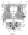
- the vacuum pumping device in accordance with the present invention comprises a substantially cylindrical turbomolecular vacuum pump 100 and an electronic control unit 1.
- the turbomolecular pump 100 comprises a substantially cylindrical casing 101, having a first portion 102 and a second portion 103, coaxial to the former and with a smaller cross section.
- the first portion 102 houses the gas pumping stages, while the second portion 103 houses an electric motor 121 and a bearing 122 for supporting the rotatable shaft 123 of the turbomolecular pump 100.
- Rotor disks 113 having flat surfaces and rotor disks 114 equipped with blades are mounted to the rotatable shaft 123 of the pump 100, cooperating with stator rings 115 and 116, respectively, that are secured to the casing 101 of the pump 100 and forming with them gas pumping channels.
- the casing 101 is further provided with an axial port 119 located at one end thereof for sucking the gases, and with a radial port 120 for exhausting the gases, located at the opposite end, this latter port being shown in Figure 5.
- a plurality of annular grooves 104 defining a series of cooling fins or rings 105 is provided on the outer surface of the first (cross-sectionally) larger portion 102 of the casing 101.
- the turbomolecular pump 100 is further provided with an annular protruding ring or flange 110 with peripherally spaced holes 117 for securing the turbomolecular pump 100 to a vessel or chamber (not shown) in which vacuum is to be created.
- a cylindrical extension 118 due to the presence within the pump 100 of the bearing and the motor is provided on casing 101, on the opposite side with respect to the flange 110, in correspondence of the base of said second smaller portion 103.
- Annular grooves 108, defining a series of cooling rings 109 are provided on the outer surface of the second smaller portion 103 of the casing 101.
- control unit 1 comprises a housing 2 having a lower resting surface 3, an upper closure surface or cover 4, and side portions or sides 5 and 6 together defining an inner space 17.
- the side 6 comprises a rounded portion 12 and two rectilinear or straight portions 13, substantially parallel to each other.
- This circuit is fed through a plurality of leads 50 for the connection to the public power distribution network and comprises two main (printed circuit) boards 56 and 55, the first one being disposed on the bottom of the housing 2 and parallel to the face 3, and the second one being near and parallel to one of the straight portions 13 of the side 6.
- a removable plug 10 for accessing to a safety fuse (not shown), a sealing ring 11 for the passage of the supply cable 50 of the electronic control unit 1, and connectors 51, 52 and 53 for the exchange of communication and control signals between unit 1 and an external unit (not shown), if required.
- the upper closure surface 4 is provided with a circular opening 16 allowing the passagge of the second portion 103 of the already discussed cylindrical casing 101 into the space 17.
- the second portion 103 is therefore completely contained inside the space provided in the housing 2, while the first portion 102 of the cylindrical casing 101 is located outside the housing 2.
- the air flow for cooling the inner space of the housing 2 is generated by a cooling fan 54 located internally to the housing 2, in correspondence of the opening 7 in the side 5.
- said symmetrical passages there are located the electronic components operating at the highest temperature of said electronic circuit, such as power transistors, microprocessors and transformers.
- a thermistor 57 for sensing the temperature of the electronic components in the control unit 1.
- the thermistor 57 is located substantially at the center of the lower circular opening 16 in the cover 4 through which the second portion 103 of the cylindrical casing 101 passes.
- the thermistor 57 is further mounted at the top of an upstanding post 59 on the board 56 parallel to the base of the the housing 2 of the control unit 1.
- the surface of the thermistor 57 is substantially in thermal contact with the cylindrical extension 118, i.e the extension due to the presence of the bearing and the pump motor inside the pump 100, when the pump 100 is inserted into the housing 2.
- a resin layer 58 is interposed between the surface of the thermistor 57 and the cylindrical extension 118.
- the thermistor 57 can be used for detecting the maximum temperature of the vacuum pumping device and generating interruption control signals when a predetermined threshold of risk is reached.
- the length of the leads 60 connecting the feeding electronic unit to the turbomolecular pump 100 is reduced to a minimum, while maintainaing said leads 60 entirely inside the housing 2.
- the electronic circuit for generating the voltage system adapted to feed the electric motor 121 comprises a pair of transistors, one pair for each phase of the voltage system, directly connected to the mains voltage and controlled by signals generated by gate drivers circuits under the control of signals generated by a microprocessor.
- the adjustment of the feeding voltage value to that required by the motor 121 of the vacuum pump 100 can be achieved, for example, by superimposing an ON/OFF pulsating signal generated by the microprocessor, having a constant frequency and a duration capable of being modulated (PWM), to one or more control signals of the gate driver circuits.
- PWM pulse width modulated
- the electronic circuit for generating a voltage system for feeding the electric motor 121 can comprises a voltage transformer that converts the voltage value of the public distribution network into a value suitable for actuating the motor of the vacuum pump.
- Suitable voltage regulators can be provided in this case to modify the level of the feeding voltage applied to the motor 121 of the vacuum pump 100.
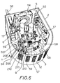
- Figures 8 and 9 illustrate a first alternative embodiment of the pumping device according to the invention providing for a substantially prismatic shape of the smaller portion 103' of the casing 101' housing the bearing of the vacuum pump 100' and the electric motor of the vacuum pump.
- the power electronic components 62 correspond to the power transistors, for example of the MOSFET type, driven by the gate drivers and directly connected to the mains voltage.
- the power components 62 are further mounted on a circular board 63 that carries the other electronic components of the feeding circuit.
- This circular board 63 and the smaller portion 103' of the casing 101' of the vacuum pump 100' are contained within the inner space 17' of a substantially cylindrical housing 2'.
- the housing 2' is further provided with two diametrally opposite series of slots 9' for the air inlet and outlet.
- the outer surface of the larger portion 102' of the casing 101' is further equipped with a plurality of annular grooves defining a series of cooling rings 105'.
- the device described with reference to Figures 8 and 9 can be equipped with a cooling system using either air or a liquid as a refrigerating fluid.
- the forced air flow is generaterd by a fan 54' located outside the vacuum pumping device and positioned between the walls of a shroud 19, formed by a box-like polyhedral member fastened to the casing 101' of the pump 100'.
- the shroud is fastened to the casing 101' and the two opposite bases thereof are open for the air inlet and outlet, so that one of the open bases is partially superimposed both to the larger portion 102' of the casing 101' - where the cooling rings 105' are located - and to the slots 9' of the housing 2' containing both the smaller portion 103' of the casing 101' of the vacuum pump 100' and the electronic components of the motor feeding circuit.
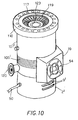
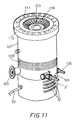
- FIG 11 illustrates a liquid cooling system of the pumping device shown in Figures 8 and 9.
- a refrigerating liquid circulates along an annular channel, substantially coplanar with the rotor disks and formed within the wall of the portion 103' of the vacuum pump 100'.
- An inlet fitting 124 and an outlet fitting 125 are provided for connecting this annular channel to delivery and return ducts (not shown) of the cooling circuit.
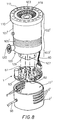
- Figure 12 illustrates a second embodiment of the pumping device according to the invention wherein the electric motor 121'' of the vacuum pump 100'' comprises a rotor 30 and a stator 31 separated by a cup-shaped casing 32 having an outwardly folded rim for securing the cup-shaped casing 32 to the body of the vacuum pump by means of screws 34.
- the electric motor 121'' of the vacuum pump 100'' comprises a rotor 30 and a stator 31 separated by a cup-shaped casing 32 having an outwardly folded rim for securing the cup-shaped casing 32 to the body of the vacuum pump by means of screws 34.
- a bearing 122 for supporting the rotor 30 of the electric motor 121''.
- the casing 101'' of the vacuum pump 100'' has a first (cross-sectionally) larger portion 102'' and a second (cross-sectionally) smaller portion 103'', this latter substantially corresponding to the cup-shaped casing 32 disposed between the rotor 30 and the stator 31 of the motor 121'' of the vacuum pump 100''.
- stator 31 of the electric motor 121'' is located outside the space of the pumping device maintained under vacuum and can be subjected to a more effective cooling, e.g. by disposing a heat sink 35 about the stator 31.
- a circular board 36 provided with a central bore and mounting the electronic components of the motor feeding circuit of the vacuum pump 100'' is secured to the base of the heat sink 35.
- the smaller portion 103'' of the casing 101'' of the vacuum pump 100'' is disposed within the space 17'' defined inside a housing 2'' having a substantially cylindrical shape.
- This housing 2'' is further equipped with aerating slots 9'' for allowing the passage of un air flow generated by a fan 54'' disposed outside of the casing 2'' and located between the walls of a shroud 19.
- the shroud 19 has opposite bases that are open for allowing the air inlet and outlet, and the shroud is preferably secured to the casing 101'' so that one of the open bases is partially superimposed to the larger portion 102'' of the casing 101'' where the cooling rings 105'' are located, and is partially superimposed to the slots 9'' of the housing 2'' containing both the smaller portion 103'' of the casing 101'' and the electronic components of the feeding circuit.
- the temperature inside the space 17'' can be controlled through a pair of thermistors 64 and 65 that are in thermal contatct with the heat sink 35 and the cup-shaped casing 32, respectively.
- FIG 13 illustrates a second embodiment of the pumping device according to the invention as described with reference to Figure 12, in which the vacuum pumping device is cooled through a liquid flow instead of an air flow.
- FIGs 14 and 15 illustrate further embodiments of the pumping devices according to the invention in which the coolant of the vacuum pumping device is air or a liquid, respectively.
- the devices are those illustrated in Figures 12 and 13, respectively, and are equipped with an electronic circuit for generating a voltage system capable to feed the electric motor of the vacuum pump and comprising a toroidal voltage transformer 40.
- the transformer 40 is located inside the casing 2'', in the same space 17'' containing the remaining electronic components of the feeding circuit.
- the transformer 40 is located between the base of the housing 2'' and the smaller portion 103'' of the casing 101'' of the vacuum pump 100''.
- the transformer 40 is fixed to the body of the vacuum pump 100'' by means of a sleeve 41 that is retained by a screw 42 against the base of the cup-shaped casing 32.
Landscapes
- Engineering & Computer Science (AREA)
- Mechanical Engineering (AREA)
- General Engineering & Computer Science (AREA)
- Physics & Mathematics (AREA)
- Thermal Sciences (AREA)
- Non-Positive Displacement Air Blowers (AREA)
- Jet Pumps And Other Pumps (AREA)
- Applications Or Details Of Rotary Compressors (AREA)
- Structures Of Non-Positive Displacement Pumps (AREA)
Applications Claiming Priority (2)
| Application Number | Priority Date | Filing Date | Title |
|---|---|---|---|
| IT96TO000821A IT1288737B1 (it) | 1996-10-08 | 1996-10-08 | Dispositivo di pompaggio da vuoto. |
| ITTO960821 | 1996-10-08 |
Publications (3)
| Publication Number | Publication Date |
|---|---|
| EP0836008A2 true EP0836008A2 (de) | 1998-04-15 |
| EP0836008A3 EP0836008A3 (de) | 1998-07-01 |
| EP0836008B1 EP0836008B1 (de) | 2002-11-20 |
Family
ID=11414944
Family Applications (1)
| Application Number | Title | Priority Date | Filing Date |
|---|---|---|---|
| EP97109427A Revoked EP0836008B1 (de) | 1996-10-08 | 1997-06-11 | Vakuumpumpgerät |
Country Status (5)
| Country | Link |
|---|---|
| US (1) | US5971725A (de) |
| EP (1) | EP0836008B1 (de) |
| JP (1) | JPH10131887A (de) |
| DE (1) | DE69717231T2 (de) |
| IT (1) | IT1288737B1 (de) |
Cited By (5)
| Publication number | Priority date | Publication date | Assignee | Title |
|---|---|---|---|---|
| WO2003040568A1 (de) * | 2001-11-09 | 2003-05-15 | Leybold Vakuum Gmbh | Vakuumpumpe |
| WO2009133394A1 (en) * | 2008-05-02 | 2009-11-05 | Edwards Limited | Vacuum pump |
| CN103089668A (zh) * | 2011-11-08 | 2013-05-08 | 株式会社岛津制作所 | 一体型涡轮分子泵 |
| US9234519B2 (en) | 2009-06-09 | 2016-01-12 | Oerlikon Leybold Vacuum Gmbh | Vacuum pump |
| EP1936198B1 (de) * | 2006-12-13 | 2018-01-24 | Pfeiffer Vacuum Gmbh | Vakuumpumpe |
Families Citing this family (51)
| Publication number | Priority date | Publication date | Assignee | Title |
|---|---|---|---|---|
| JP4104098B2 (ja) * | 1999-03-31 | 2008-06-18 | エドワーズ株式会社 | 真空ポンプ |
| US6149406A (en) * | 1999-09-07 | 2000-11-21 | Chang; Chin-Chin | Heat dissipating fan for an induction motor |
| GB9921983D0 (en) * | 1999-09-16 | 1999-11-17 | Boc Group Plc | Improvements in vacuum pumps |
| DE19951954A1 (de) * | 1999-10-28 | 2001-05-03 | Pfeiffer Vacuum Gmbh | Turbomolekularpumpe |
| US6314749B1 (en) * | 2000-02-03 | 2001-11-13 | Leon R. Van Steenburgh, Jr. | Self-clearing vacuum pump with external cooling for evacuating refrigerant storage devices and systems |
| JP3482373B2 (ja) * | 2000-04-28 | 2003-12-22 | ミネベア株式会社 | 送風機 |
| JP2002276587A (ja) * | 2001-03-19 | 2002-09-25 | Boc Edwards Technologies Ltd | ターボ分子ポンプ |
| JP2003269369A (ja) * | 2002-03-13 | 2003-09-25 | Boc Edwards Technologies Ltd | 真空ポンプ |
| JP2003269367A (ja) * | 2002-03-13 | 2003-09-25 | Boc Edwards Technologies Ltd | 真空ポンプ |
| DE10354205A1 (de) * | 2003-11-20 | 2005-06-23 | Leybold Vakuum Gmbh | Verfahren zur Steuerung eines Antriebsmotors einer Vakuum-Verdrängerpumpe |
| US6982532B2 (en) | 2003-12-08 | 2006-01-03 | A. O. Smith Corporation | Electric machine |
| JP2006242069A (ja) * | 2005-03-02 | 2006-09-14 | Shimadzu Corp | ターボ分子ポンプ |
| DE102006016405B4 (de) * | 2006-04-07 | 2024-08-01 | Pfeiffer Vacuum Gmbh | Vakuumpumpe mit Antriebsgerät |
| US7729118B2 (en) * | 2006-11-03 | 2010-06-01 | Fu Zhun Precision Industry (Shen Zhen) Co., Ltd. | Miniature liquid cooling device having an integral pump |
| WO2008062598A1 (en) * | 2006-11-22 | 2008-05-29 | Edwards Japan Limited | Vacuum pump |
| DE102006058842A1 (de) * | 2006-12-13 | 2008-06-19 | Pfeiffer Vacuum Gmbh | Vakuumpumpe mit Lüfter |
| US20090047158A1 (en) * | 2007-08-13 | 2009-02-19 | Hsing Lei-Shung | Self-cooling back-connect driver motor assembly |
| DE202007012070U1 (de) * | 2007-08-30 | 2009-01-08 | Oerlikon Leybold Vacuum Gmbh | Stromdurchführung einer Vakuumpumpe |
| JP5211408B2 (ja) * | 2008-10-14 | 2013-06-12 | 株式会社大阪真空機器製作所 | 分子ポンプのロータ |
| JP5218220B2 (ja) * | 2009-03-31 | 2013-06-26 | 株式会社島津製作所 | ターボ分子ポンプ装置およびその制御装置 |
| JP5545358B2 (ja) * | 2010-03-11 | 2014-07-09 | 株式会社島津製作所 | ターボ分子ポンプ装置 |
| KR101047300B1 (ko) | 2010-03-23 | 2011-07-07 | 문명선 | 진공챔버용 모터의 냉각장치 |
| JP5353838B2 (ja) * | 2010-07-07 | 2013-11-27 | 株式会社島津製作所 | 真空ポンプ |
| CN103228923B (zh) * | 2010-10-19 | 2016-09-21 | 埃地沃兹日本有限公司 | 真空泵 |
| DE102011088976A1 (de) * | 2011-01-31 | 2012-08-02 | Continental Automotive Gmbh | Anordnung zur Ansteuerung einer elektrischen Vakuum-Pumpe |
| CN103047152B (zh) * | 2011-10-17 | 2016-06-22 | 株式会社岛津制作所 | 真空泵 |
| JP5768670B2 (ja) * | 2011-11-09 | 2015-08-26 | 株式会社島津製作所 | ターボ分子ポンプ装置 |
| GB2498816A (en) | 2012-01-27 | 2013-07-31 | Edwards Ltd | Vacuum pump |
| DE202013008468U1 (de) * | 2013-09-24 | 2015-01-08 | Oerlikon Leybold Vacuum Gmbh | Vakuumpumpengehäuse |
| KR101637827B1 (ko) * | 2015-04-13 | 2016-07-07 | 엘지전자 주식회사 | 진공 청소기 |
| US10851793B2 (en) * | 2016-01-14 | 2020-12-01 | Lg Innotek Co., Ltd. | Fan motor comprising a housing and a printed circuit board disposed outside of a lower housing and coupled to a concavely formed board coupling portion at a lower surface of the housing |
| JP6642033B2 (ja) * | 2016-01-22 | 2020-02-05 | 株式会社島津製作所 | 真空ポンプ用電源装置 |
| GB2553321A (en) * | 2016-09-01 | 2018-03-07 | Edwards Ltd | Pump |
| JP6753759B2 (ja) * | 2016-10-21 | 2020-09-09 | エドワーズ株式会社 | 真空ポンプ及び該真空ポンプに適用される防水構造、制御装置 |
| JP6852457B2 (ja) * | 2017-02-27 | 2021-03-31 | 株式会社島津製作所 | 電源一体型真空ポンプ |
| JP6916413B2 (ja) * | 2017-04-25 | 2021-08-11 | 株式会社島津製作所 | 電源一体型真空ポンプ |
| JP6834814B2 (ja) * | 2017-06-30 | 2021-02-24 | 株式会社島津製作所 | 真空ポンプ用制御装置および真空ポンプ |
| JP7022265B2 (ja) * | 2017-10-25 | 2022-02-18 | 株式会社島津製作所 | 真空ポンプ |
| JP7087418B2 (ja) * | 2018-02-02 | 2022-06-21 | 株式会社島津製作所 | 真空ポンプ |
| JP7088688B2 (ja) * | 2018-02-16 | 2022-06-21 | エドワーズ株式会社 | 真空ポンプと真空ポンプの制御装置 |
| JP7096006B2 (ja) * | 2018-02-16 | 2022-07-05 | エドワーズ株式会社 | 真空ポンプと真空ポンプの制御装置 |
| JP6954238B2 (ja) * | 2018-07-04 | 2021-10-27 | 株式会社島津製作所 | 真空ポンプ用電源装置および真空ポンプ装置 |
| DE102018219253A1 (de) * | 2018-11-12 | 2020-05-14 | KSB SE & Co. KGaA | Elektromotor |
| JP7244328B2 (ja) * | 2019-03-28 | 2023-03-22 | エドワーズ株式会社 | 真空ポンプ及び該真空ポンプの制御装置 |
| JP7220692B2 (ja) * | 2019-10-07 | 2023-02-10 | プファイファー・ヴァキューム・ゲーエムベーハー | 真空ポンプ、スクロールポンプ及びその製造方法 |
| EP3754200B1 (de) | 2019-10-07 | 2021-12-08 | Pfeiffer Vacuum Gmbh | Scrollvakuumpumpe und montageverfahren |
| CN214092394U (zh) * | 2020-12-17 | 2021-08-31 | 中山大洋电机股份有限公司 | 一种直流引风机 |
| JP7533324B2 (ja) * | 2021-04-01 | 2024-08-14 | 株式会社島津製作所 | 真空ポンプ |
| EP4663959A3 (de) * | 2021-12-30 | 2026-03-11 | Pfeiffer Vacuum Technology AG | Vakuumpumpe |
| KR102522429B1 (ko) * | 2022-07-07 | 2023-04-19 | 주식회사 부쉬코리아 | 냉각을 위한 방폭팬과 라디에이터를 포함하는 진공펌프유닛 |
| JP2024176741A (ja) * | 2023-06-09 | 2024-12-19 | 株式会社島津製作所 | 真空ポンプ |
Family Cites Families (8)
| Publication number | Priority date | Publication date | Assignee | Title |
|---|---|---|---|---|
| US4722669A (en) * | 1985-03-25 | 1988-02-02 | Control Resources, Inc. | Fan speed controller |
| US5443368A (en) * | 1993-07-16 | 1995-08-22 | Helix Technology Corporation | Turbomolecular pump with valves and integrated electronic controls |
| US5238362A (en) * | 1990-03-09 | 1993-08-24 | Varian Associates, Inc. | Turbomolecular pump |
| IT1241431B (it) * | 1990-03-09 | 1994-01-17 | Varian Spa | Pompa turbomolecolare perfezionata. |
| JP2998441B2 (ja) * | 1992-08-19 | 2000-01-11 | 株式会社日立製作所 | ターボ真空ポンプ |
| DE4237971B4 (de) * | 1992-11-11 | 2004-05-06 | Unaxis Deutschland Holding Gmbh | Vakuumpumpe mit Wandler |
| US5368446A (en) * | 1993-01-22 | 1994-11-29 | Copeland Corporation | Scroll compressor having high temperature control |
| DE9417422U1 (de) * | 1994-10-31 | 1995-02-09 | Leybold AG, 50968 Köln | Reibungsvakuumpumpe mit Gehäuse |
-
1996
- 1996-10-08 IT IT96TO000821A patent/IT1288737B1/it active IP Right Grant
-
1997
- 1997-06-11 EP EP97109427A patent/EP0836008B1/de not_active Revoked
- 1997-06-11 DE DE69717231T patent/DE69717231T2/de not_active Revoked
- 1997-10-07 US US08/958,208 patent/US5971725A/en not_active Expired - Lifetime
- 1997-10-08 JP JP9290524A patent/JPH10131887A/ja active Pending
Cited By (8)
| Publication number | Priority date | Publication date | Assignee | Title |
|---|---|---|---|---|
| WO2003040568A1 (de) * | 2001-11-09 | 2003-05-15 | Leybold Vakuum Gmbh | Vakuumpumpe |
| US6999840B2 (en) | 2001-11-09 | 2006-02-14 | Leybold Vakuum Gmbh | Vacuum pump |
| EP1936198B1 (de) * | 2006-12-13 | 2018-01-24 | Pfeiffer Vacuum Gmbh | Vakuumpumpe |
| WO2009133394A1 (en) * | 2008-05-02 | 2009-11-05 | Edwards Limited | Vacuum pump |
| US9234519B2 (en) | 2009-06-09 | 2016-01-12 | Oerlikon Leybold Vacuum Gmbh | Vacuum pump |
| EP2440788B1 (de) * | 2009-06-09 | 2017-01-18 | Leybold GmbH | Vakuumpumpe |
| CN103089668A (zh) * | 2011-11-08 | 2013-05-08 | 株式会社岛津制作所 | 一体型涡轮分子泵 |
| CN103089668B (zh) * | 2011-11-08 | 2015-09-02 | 株式会社岛津制作所 | 一体型涡轮分子泵 |
Also Published As
| Publication number | Publication date |
|---|---|
| EP0836008A3 (de) | 1998-07-01 |
| EP0836008B1 (de) | 2002-11-20 |
| DE69717231D1 (de) | 2003-01-02 |
| JPH10131887A (ja) | 1998-05-19 |
| DE69717231T2 (de) | 2003-09-11 |
| IT1288737B1 (it) | 1998-09-24 |
| ITTO960821A1 (it) | 1998-04-08 |
| US5971725A (en) | 1999-10-26 |
Similar Documents
| Publication | Publication Date | Title |
|---|---|---|
| EP0836008B1 (de) | Vakuumpumpgerät | |
| EP0913910B1 (de) | Pumpenmotor mit Flüssigkeitskühlungsystem | |
| CN107453551B (zh) | 带有增强的空气冷却的具有切向结构的电机 | |
| US6841957B2 (en) | Low profile motor | |
| US20090289513A1 (en) | Cooling System for a Motor and Associated Electronics | |
| US10833566B2 (en) | Inverter integrated motor | |
| US20250052245A1 (en) | Integrated electric motor drive and dry runner centrifugal pump assembly with such an integrated electric motor drive | |
| US9543807B2 (en) | Electric motor | |
| EP3551891B1 (de) | Vakuumpumpe mit anordnung zur kühlung des motors und der steuereinheit | |
| CN115943260A (zh) | 具有冷却的两部分电子模块的泵马达 | |
| US3458739A (en) | Air cooled motor | |
| US5940576A (en) | Electronic control unit for a vacuum pump | |
| WO2021150584A1 (en) | Motor assembly for driving a pump or rotary device having a cooling duct | |
| US7101157B2 (en) | Cooling arrangement for an electromotor | |
| JP2000209810A (ja) | モ―タ機器における電力半導体素子の固定構造及び流体ポンプ装置 | |
| JP3830209B2 (ja) | 可変速ポンプ装置 | |
| WO2023110448A1 (en) | Pump assembly | |
| JP2023545202A (ja) | 駆動装置を備えた遠心ポンプ | |
| GB2557360A (en) | Vacuum Pump | |
| JP2004316548A (ja) | 液体電動ポンプの制御器冷却構造 | |
| CN220291828U (zh) | 电机和泵 | |
| WO2024260636A1 (en) | Pump assembly and method for operating such | |
| JPS62178800A (ja) | 電動ポンプ | |
| JP2005054730A (ja) | キャビネット型の給水装置 | |
| GB2642512A (en) | Compressor housing |
Legal Events
| Date | Code | Title | Description |
|---|---|---|---|
| PUAI | Public reference made under article 153(3) epc to a published international application that has entered the european phase |
Free format text: ORIGINAL CODE: 0009012 |
|
| AK | Designated contracting states |
Kind code of ref document: A2 Designated state(s): DE FR GB IT |
|
| AX | Request for extension of the european patent |
Free format text: AL;LT;LV;RO;SI |
|
| PUAL | Search report despatched |
Free format text: ORIGINAL CODE: 0009013 |
|
| AK | Designated contracting states |
Kind code of ref document: A3 Designated state(s): AT BE CH DE DK ES FI FR GB GR IE IT LI LU MC NL PT SE |
|
| AX | Request for extension of the european patent |
Free format text: AL;LT;LV;RO;SI |
|
| 17P | Request for examination filed |
Effective date: 19980820 |
|
| AKX | Designation fees paid |
Free format text: DE FR GB IT |
|
| RBV | Designated contracting states (corrected) |
Designated state(s): DE FR GB IT |
|
| GRAG | Despatch of communication of intention to grant |
Free format text: ORIGINAL CODE: EPIDOS AGRA |
|
| 17Q | First examination report despatched |
Effective date: 20020325 |
|
| GRAG | Despatch of communication of intention to grant |
Free format text: ORIGINAL CODE: EPIDOS AGRA |
|
| GRAH | Despatch of communication of intention to grant a patent |
Free format text: ORIGINAL CODE: EPIDOS IGRA |
|
| GRAH | Despatch of communication of intention to grant a patent |
Free format text: ORIGINAL CODE: EPIDOS IGRA |
|
| GRAA | (expected) grant |
Free format text: ORIGINAL CODE: 0009210 |
|
| AK | Designated contracting states |
Kind code of ref document: B1 Designated state(s): DE FR GB IT |
|
| REG | Reference to a national code |
Ref country code: GB Ref legal event code: FG4D |
|
| REF | Corresponds to: |
Ref document number: 69717231 Country of ref document: DE Date of ref document: 20030102 |
|
| ET | Fr: translation filed | ||
| PLBI | Opposition filed |
Free format text: ORIGINAL CODE: 0009260 |
|
| PLBQ | Unpublished change to opponent data |
Free format text: ORIGINAL CODE: EPIDOS OPPO |
|
| PLAX | Notice of opposition and request to file observation + time limit sent |
Free format text: ORIGINAL CODE: EPIDOSNOBS2 |
|
| 26 | Opposition filed |
Opponent name: PFEIFFER VACUUM GMBH Effective date: 20030814 |
|
| PLAX | Notice of opposition and request to file observation + time limit sent |
Free format text: ORIGINAL CODE: EPIDOSNOBS2 |
|
| PLBB | Reply of patent proprietor to notice(s) of opposition received |
Free format text: ORIGINAL CODE: EPIDOSNOBS3 |
|
| PLCK | Communication despatched that opposition was rejected |
Free format text: ORIGINAL CODE: EPIDOSNREJ1 |
|
| APBP | Date of receipt of notice of appeal recorded |
Free format text: ORIGINAL CODE: EPIDOSNNOA2O |
|
| APBM | Appeal reference recorded |
Free format text: ORIGINAL CODE: EPIDOSNREFNO |
|
| APBQ | Date of receipt of statement of grounds of appeal recorded |
Free format text: ORIGINAL CODE: EPIDOSNNOA3O |
|
| APAH | Appeal reference modified |
Free format text: ORIGINAL CODE: EPIDOSCREFNO |
|
| PGFP | Annual fee paid to national office [announced via postgrant information from national office to epo] |
Ref country code: FR Payment date: 20060428 Year of fee payment: 10 |
|
| PGFP | Annual fee paid to national office [announced via postgrant information from national office to epo] |
Ref country code: GB Payment date: 20060607 Year of fee payment: 10 |
|
| PGFP | Annual fee paid to national office [announced via postgrant information from national office to epo] |
Ref country code: IT Payment date: 20060630 Year of fee payment: 10 Ref country code: DE Payment date: 20060630 Year of fee payment: 10 |
|
| APBU | Appeal procedure closed |
Free format text: ORIGINAL CODE: EPIDOSNNOA9O |
|
| RDAF | Communication despatched that patent is revoked |
Free format text: ORIGINAL CODE: EPIDOSNREV1 |
|
| PLBN | Opposition rejected |
Free format text: ORIGINAL CODE: 0009273 |
|
| RDAG | Patent revoked |
Free format text: ORIGINAL CODE: 0009271 |
|
| STAA | Information on the status of an ep patent application or granted ep patent |
Free format text: STATUS: PATENT REVOKED |
|
| 27O | Opposition rejected |
Effective date: 20070515 |
|
| 27W | Patent revoked |
Effective date: 20070515 |
|
| GBPR | Gb: patent revoked under art. 102 of the ep convention designating the uk as contracting state |
Free format text: 20070515 |