EP0836010A1 - Pompe de drainage - Google Patents
Pompe de drainage Download PDFInfo
- Publication number
- EP0836010A1 EP0836010A1 EP97117317A EP97117317A EP0836010A1 EP 0836010 A1 EP0836010 A1 EP 0836010A1 EP 97117317 A EP97117317 A EP 97117317A EP 97117317 A EP97117317 A EP 97117317A EP 0836010 A1 EP0836010 A1 EP 0836010A1
- Authority
- EP
- European Patent Office
- Prior art keywords
- vane
- small
- pump chamber
- pump
- drainage
- Prior art date
- Legal status (The legal status is an assumption and is not a legal conclusion. Google has not performed a legal analysis and makes no representation as to the accuracy of the status listed.)
- Granted
Links
- 238000007599 discharging Methods 0.000 claims abstract description 9
- 230000002093 peripheral effect Effects 0.000 claims abstract description 8
- XLYOFNOQVPJJNP-UHFFFAOYSA-N water Substances O XLYOFNOQVPJJNP-UHFFFAOYSA-N 0.000 abstract description 9
- 239000003657 drainage water Substances 0.000 description 15
- 230000007423 decrease Effects 0.000 description 4
- 230000003247 decreasing effect Effects 0.000 description 2
- 230000000630 rising effect Effects 0.000 description 2
- 239000006096 absorbing agent Substances 0.000 description 1
- 238000001816 cooling Methods 0.000 description 1
- 230000000670 limiting effect Effects 0.000 description 1
- 230000035939 shock Effects 0.000 description 1
Images

Classifications
-
- F—MECHANICAL ENGINEERING; LIGHTING; HEATING; WEAPONS; BLASTING
- F04—POSITIVE - DISPLACEMENT MACHINES FOR LIQUIDS; PUMPS FOR LIQUIDS OR ELASTIC FLUIDS
- F04D—NON-POSITIVE-DISPLACEMENT PUMPS
- F04D1/00—Radial-flow pumps, e.g. centrifugal pumps; Helico-centrifugal pumps
- F04D1/02—Radial-flow pumps, e.g. centrifugal pumps; Helico-centrifugal pumps having non-centrifugal stages, e.g. centripetal
-
- F—MECHANICAL ENGINEERING; LIGHTING; HEATING; WEAPONS; BLASTING
- F04—POSITIVE - DISPLACEMENT MACHINES FOR LIQUIDS; PUMPS FOR LIQUIDS OR ELASTIC FLUIDS
- F04D—NON-POSITIVE-DISPLACEMENT PUMPS
- F04D29/00—Details, component parts, or accessories
- F04D29/40—Casings; Connections of working fluid
- F04D29/42—Casings; Connections of working fluid for radial or helico-centrifugal pumps
- F04D29/44—Fluid-guiding means, e.g. diffusers
- F04D29/445—Fluid-guiding means, e.g. diffusers especially adapted for liquid pumps
Definitions
- the present invention relates to drainage pumps and, more particularly, to drainage pumps equipped in air conditioners.
- a prior art drainage pump comprises a housing having a suction inlet at the lower portion, an opening at the upper portion, and a discharging outlet on the side, and a vane mounted rotatively inside the housing, wherein said vane rotates by a motor fixed via a cover to the upper portion of the opening of the housing.
- the rotation shaft of the motor extends through the cover rotatively and is connected to the shaft of the vane.
- the cover is equipped with a through hole for connecting air and the housing.
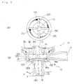
- FIG. 3 The operation of a drainage pump of the prior art of the above type disclosed in Japanese Patent Laid-Open No. H8-144996 is shown in FIG. 3.
- (A) shows the upper view of the interior of the drainage pump
- (B) shows the front view of the interior of the drainage pump
- G 2 shows the bubbles.
- a pump body 10 of a drainage pump 1A comprises a pump chamber 12, a suction inlet 15 and a discharging outlet 17.
- a rotation vane 100 equipped inside the body 10 is connected to a motor (not shown) mounted on the upper portion of the pump body 10 and comprises a shaft 110, four large vanes 120 and a cutwater board 34, wherein a gap 32 is formed between the shaft 110 and the cover 30 of the body.
- Underneath the large vane 120 is a small vane 130 for raising the drainage water sucked in from the suction inlet.
- a disc 150 is connected to the lower peripheral of the large vane 120.
- the disc 150 includes a hollow portion 155 for keeping back and dividing a portion of the drainage water rising from the suction inlet.
- the present invention aims at providing a drainage pump with decreased noise even when the stage of the water is high or the lift is high.
- the drainage pump of the present invention comprises a motor, a rotation vane connected to a driving shaft of the motor, and a pump body for accommodating the rotation vane
- the rotation vane comprises a shaft portion connected to the driving shaft of the motor, a plurality of plate-shaped large vanes extending to the radial direction from the outer peripheral of the shaft portion, a small vane formed to extend to the lower direction of said large vane and parallel to said shaft portion, and a ring mounted between said large vane and said small vane and having an opening in its center portion
- said pump body comprises a cylindrical-shaped small vane pump chamber for accommodating said small vane and whose end portion being connected to a suction inlet, a large vane pump chamber for accommodating said large vane and whose peripheral wall portion being connected to a discharging outlet, and a slope portion formed on the connection between the small vane pump chamber and the large vane pump chamber.
- Such structure allows the drainage water to widen toward the radial direction along the slope portion when it rises along the small vane pump chamber even when the stage of the water or the lift is high.
- the liquid-vapor boundary surface will be divided by the ring, and a portion of the drainage water will be kept back, reducing the amount of water contacting the large vane at the upper portion of the ring and the load to be received by the rotation vane.
- the collision of the bubble against the vane will decrease, and thus noise and vibration will be decreased.
- FIG. 1 is an explanatory view showing a cross-sectional view of the body of the drainage pump and the front view of the rotation vane of the present invention.
- the body 200 of the drainage pump of the present invention includes a suction inlet 210 and a discharging outlet 220.
- a rotation vane 300 positioned inside the body 200 comprises a small vane 350 having four plate-type vanes extending to the radial direction, and a large vane 320 connected to the small vane 350.
- the peripheral of the large vane 320 is surrounded by a circumference wall 325, and a tapered ring 330 is connected to the lower end of the circumference wall 325 covering the low end of the large vane 320.
- a rim portion 360 of the large vane 320 continuing to the small vane 350 is formed in a tapered shape.
- the center of the tapered ring 330 has an opening 332 which connects through to the area of the small vane 350.
- the upper portion of the pump body 200 is covered by a cover member 215, and a shaft 310 of the rotation vane 300 passes through a through hole 217 of the cover member 215 and projects toward the driving shaft of the motor.
- the pump body 200 comprises a small vane pump chamber 230 for accommodating the small vane 350 and a large vane pump chamber 240 surrounding the large vane 320, wherein the cylindrical small vane pump chamber 230 and the large vane pump chamber 240 is connected by a slope portion 250.
- the outer rim of the rotation vane 300 opposing the slope portion 250 of the body 200 is also formed as a slope portion 360.
- the angle of the slope portion 250 of the body 200 and the angle of the slope portion 360 of the rotation vane 300 are substantially the same.
- FIG. 2 is a cross-sectional view explaining the shape of the liquid-vapor boundary surface W 3 formed on the inner side of the drainage flow inside the pump body 200 when the drainage pump is operated.
- the small vane pump chamber 230 of the body 200 and the large vane pump chamber 240 are connected by the slope portion 250, so the drainage water rotating and rising along the inner wall of the small vane pump chamber 230 by the centrifugal force caused by the rotation of the small vane 350 is expanded to the radial direction along the slope portion 250.
- the liquid-vapor boundary surface W 3 is likely to expand, forming a parabola with large radius size.
- the liquid-vapor boundary surface W 3 will therefore be divided by the tapered ring 330, a portion of the drainage water will be kept back, the amount of drainage water contacting the large vane 320 will be reduced, resulting in the reduction of the collision of the bubbles against the large vane, and low noise could be realized. Further, the load of the motor could be reduced. Therefore, low noise could be maintained even when the stage of the water or the lift is high.
- the drainage pump of the present invention comprising a rotation vane having a shaft portion connected to the driving shaft of the motor, a plurality of plate-shaped large vanes extending to the radial direction from the outer peripheral of the shaft portion, a plate-shaped small vane formed continuously to the lower rim of the large vane, and a slope portion formed on the connecting point of the large vane and the small vane, wherein a pump body accommodates said small vane, the end portion thereof accommodates a cylindrical small vane pump chamber and a large vane pump chamber, and having a slope portion formed on the connecting portion of the small vane pump chamber and the large vane pump chamber, a desirable liquid-vapor boundary surface could be achieved when the stage of the water or the lift is high, enabling improved performance of the pump.
Landscapes
- Engineering & Computer Science (AREA)
- Mechanical Engineering (AREA)
- General Engineering & Computer Science (AREA)
- Structures Of Non-Positive Displacement Pumps (AREA)
Applications Claiming Priority (3)
| Application Number | Priority Date | Filing Date | Title |
|---|---|---|---|
| JP270008/96 | 1996-10-11 | ||
| JP27000896 | 1996-10-11 | ||
| JP27000896A JP3910665B2 (ja) | 1996-10-11 | 1996-10-11 | 排水ポンプ |
Publications (2)
| Publication Number | Publication Date |
|---|---|
| EP0836010A1 true EP0836010A1 (fr) | 1998-04-15 |
| EP0836010B1 EP0836010B1 (fr) | 2003-07-09 |
Family
ID=17480273
Family Applications (1)
| Application Number | Title | Priority Date | Filing Date |
|---|---|---|---|
| EP97117317A Expired - Lifetime EP0836010B1 (fr) | 1996-10-11 | 1997-10-07 | Pompe de drainage |
Country Status (7)
| Country | Link |
|---|---|
| US (1) | US5961283A (fr) |
| EP (1) | EP0836010B1 (fr) |
| JP (1) | JP3910665B2 (fr) |
| KR (1) | KR100433506B1 (fr) |
| CN (1) | CN1093606C (fr) |
| DE (1) | DE69723387T2 (fr) |
| TW (1) | TW489948U (fr) |
Cited By (1)
| Publication number | Priority date | Publication date | Assignee | Title |
|---|---|---|---|---|
| EP3171032A1 (fr) * | 2015-11-18 | 2017-05-24 | Fujikoki Corporation | Pompe d'épuisement |
Families Citing this family (5)
| Publication number | Priority date | Publication date | Assignee | Title |
|---|---|---|---|---|
| JP3511044B2 (ja) | 2000-06-21 | 2004-03-29 | 株式会社鷺宮製作所 | ドレン排水ポンプ |
| JP3711998B2 (ja) | 2003-12-05 | 2005-11-02 | ダイキン工業株式会社 | ドレンポンプ及びそれを備えた空気調和装置 |
| JP2006029214A (ja) * | 2004-07-16 | 2006-02-02 | Fuji Koki Corp | 排水ポンプ |
| JP4937313B2 (ja) * | 2009-08-07 | 2012-05-23 | 株式会社不二工機 | 排水ポンプ |
| JP7515857B2 (ja) * | 2020-05-26 | 2024-07-16 | 株式会社不二工機 | 排水ポンプ |
Citations (4)
| Publication number | Priority date | Publication date | Assignee | Title |
|---|---|---|---|---|
| EP0511352A1 (fr) * | 1990-11-15 | 1992-11-04 | Fico Transpar, S.A. | Pompe destinee a un dispositif de lavage de pare-brise et pourvue d'un dispositif de detection de niveau |
| DE4128535A1 (de) * | 1991-08-28 | 1993-03-04 | Hella Kg Hueck & Co | Kreiselpumpe, insbesondere waschwasserpumpe fuer scheiben von kraftfahrzeugen |
| EP0683323A1 (fr) * | 1994-05-18 | 1995-11-22 | Societe D'etudes Et De Realisations Industrielles Et Commerciales Seric | Plongeur destiné à une pompe du type de celles destinées aux lave-vitres de véhicule automobile |
| EP0713978A1 (fr) | 1994-11-25 | 1996-05-29 | Fujikoki Mfg. Co., Ltd. | Pompe de drainage |
Family Cites Families (25)
| Publication number | Priority date | Publication date | Assignee | Title |
|---|---|---|---|---|
| GB1039426A (fr) * | 1900-01-01 | |||
| US1512243A (en) * | 1923-06-19 | 1924-10-21 | John L Shrode | Automatic expansion valve |
| US1987948A (en) * | 1933-08-01 | 1935-01-15 | Fedders Mfg Co Inc | Refrigerant control device |
| US2306768A (en) * | 1936-09-11 | 1942-12-29 | Detroit Lubricator Co | Control device |
| FR831073A (fr) * | 1936-12-23 | 1938-08-22 | D App Electr Fr Sauter S A Fab | Valve d'injection à commande thermostatique pour appareils frigorifiques à l'ammoniaque |
| US2361750A (en) * | 1943-02-10 | 1944-10-31 | Curtis Pump Co | Booster pump impeller construction |
| US2642510A (en) * | 1949-06-06 | 1953-06-16 | Mechanical Products Inc | Switch |
| GB709767A (en) * | 1952-01-29 | 1954-06-02 | Mechanical Products Inc | Improvements in and relating to electric circuit breakers |
| FR1050101A (fr) * | 1952-02-01 | 1954-01-05 | Obturateur de détente, notamment pour appareils frigorifiques | |
| US3290021A (en) * | 1963-11-29 | 1966-12-06 | Oster Mfg Co John | Portable humidifier |
| US3746465A (en) * | 1971-08-11 | 1973-07-17 | Lummus Industries | Centrifugal fan for handling material |
| US3758236A (en) * | 1971-10-14 | 1973-09-11 | March Manuf Co | Condensate pump |
| US4637779A (en) * | 1985-05-17 | 1987-01-20 | Kamyr, Inc. | Two stage medium consistency pulp pumping |
| US4826398A (en) * | 1987-07-06 | 1989-05-02 | Kamyr Ab | Medium consistency pump with self-feeding |
| US4815698A (en) * | 1988-05-02 | 1989-03-28 | Strahman Valves, Inc. | Hard seated valve |
| CH678352A5 (fr) * | 1988-06-23 | 1991-08-30 | Sulzer Ag | |
| US4890980A (en) * | 1988-08-08 | 1990-01-02 | Ingersoll-Rand Company | Centrifugal pump |
| GB2225814B (en) * | 1988-12-06 | 1993-03-24 | Johnston Eng Ltd | Fan impellers for road sweeping vehicles |
| US5209641A (en) * | 1989-03-29 | 1993-05-11 | Kamyr Ab | Apparatus for fluidizing, degassing and pumping a suspension of fibrous cellulose material |
| US4940385A (en) * | 1989-04-25 | 1990-07-10 | Gurth Max Ira | Rotary disc pump |
| FR2651839B1 (fr) * | 1989-09-22 | 1992-07-10 | Seeley Nominees Pty Ltd Ff | Pompe immergee. |
| JPH05322381A (ja) * | 1992-05-25 | 1993-12-07 | Mitsubishi Heavy Ind Ltd | 膨張弁装置 |
| NL9201782A (nl) * | 1992-10-14 | 1994-05-02 | Hubert Stavoren Bv | Inrichting en werkwijze voor het beluchten van afvalwater. |
| JP3282772B2 (ja) * | 1994-11-25 | 2002-05-20 | 株式会社不二工機 | 排水ポンプ |
| JP3580329B2 (ja) * | 1995-08-29 | 2004-10-20 | 株式会社不二工機 | 排水ポンプ |
-
1996
- 1996-10-11 JP JP27000896A patent/JP3910665B2/ja not_active Expired - Lifetime
-
1997
- 1997-05-14 CN CN97111165A patent/CN1093606C/zh not_active Expired - Lifetime
- 1997-06-11 TW TW090215044U patent/TW489948U/zh not_active IP Right Cessation
- 1997-06-14 KR KR1019970024779A patent/KR100433506B1/ko not_active Expired - Lifetime
- 1997-09-11 US US08/927,690 patent/US5961283A/en not_active Expired - Lifetime
- 1997-10-07 EP EP97117317A patent/EP0836010B1/fr not_active Expired - Lifetime
- 1997-10-07 DE DE69723387T patent/DE69723387T2/de not_active Expired - Lifetime
Patent Citations (4)
| Publication number | Priority date | Publication date | Assignee | Title |
|---|---|---|---|---|
| EP0511352A1 (fr) * | 1990-11-15 | 1992-11-04 | Fico Transpar, S.A. | Pompe destinee a un dispositif de lavage de pare-brise et pourvue d'un dispositif de detection de niveau |
| DE4128535A1 (de) * | 1991-08-28 | 1993-03-04 | Hella Kg Hueck & Co | Kreiselpumpe, insbesondere waschwasserpumpe fuer scheiben von kraftfahrzeugen |
| EP0683323A1 (fr) * | 1994-05-18 | 1995-11-22 | Societe D'etudes Et De Realisations Industrielles Et Commerciales Seric | Plongeur destiné à une pompe du type de celles destinées aux lave-vitres de véhicule automobile |
| EP0713978A1 (fr) | 1994-11-25 | 1996-05-29 | Fujikoki Mfg. Co., Ltd. | Pompe de drainage |
Cited By (1)
| Publication number | Priority date | Publication date | Assignee | Title |
|---|---|---|---|---|
| EP3171032A1 (fr) * | 2015-11-18 | 2017-05-24 | Fujikoki Corporation | Pompe d'épuisement |
Also Published As
| Publication number | Publication date |
|---|---|
| CN1220351A (zh) | 1999-06-23 |
| EP0836010B1 (fr) | 2003-07-09 |
| JPH10115294A (ja) | 1998-05-06 |
| DE69723387D1 (de) | 2003-08-14 |
| CN1093606C (zh) | 2002-10-30 |
| KR19980032163A (ko) | 1998-07-25 |
| TW489948U (en) | 2002-06-01 |
| DE69723387T2 (de) | 2004-04-22 |
| KR100433506B1 (ko) | 2004-09-01 |
| US5961283A (en) | 1999-10-05 |
| JP3910665B2 (ja) | 2007-04-25 |
Similar Documents
| Publication | Publication Date | Title |
|---|---|---|
| EP0760428B1 (fr) | Pompe de drainage | |
| KR100413177B1 (ko) | 원심 다익 팬 | |
| US7670105B2 (en) | Drain pump, and air conditioner provided therewith | |
| JPH0886299A (ja) | 遠心式送風機 | |
| JP3511044B2 (ja) | ドレン排水ポンプ | |
| EP0836010B1 (fr) | Pompe de drainage | |
| EP1024297B1 (fr) | Pompe de vidange | |
| JP2001123977A (ja) | ドレン排水ポンプ | |
| JP2908370B2 (ja) | 遠心形多翼送風機 | |
| JP3647939B2 (ja) | 排水ポンプ | |
| JP3282772B2 (ja) | 排水ポンプ | |
| JPH0533797A (ja) | 押し込み式軸流フアン | |
| JP3410406B2 (ja) | 液体排水ポンプ | |
| JPH116497A (ja) | 遠心形多翼送風機 | |
| JP2005030261A (ja) | 排水ポンプ | |
| JPH09145085A (ja) | ドレン排水ポンプ | |
| JP2001207987A (ja) | ドレン排水用ポンプ | |
| KR0164696B1 (ko) | 공기배출이 원활한 구조의 온수순환펌프 | |
| JP3864271B2 (ja) | ドレン排水ポンプ | |
| HK1049687B (zh) | 风机叶轮和风机,尤其是径向风机 | |
| KR19990056524A (ko) | 송풍기 유니트 | |
| JP2006083772A (ja) | 遠心送風機 | |
| KR19990046916A (ko) | 컨버터블 에어콘용 실내기의 풍량증대 및 소음저감구조 | |
| KR20050021810A (ko) | 팬과 쉬라우드의 조립체 | |
| JP2007107455A (ja) | 非自吸式ポンプ |
Legal Events
| Date | Code | Title | Description |
|---|---|---|---|
| PUAI | Public reference made under article 153(3) epc to a published international application that has entered the european phase |
Free format text: ORIGINAL CODE: 0009012 |
|
| AK | Designated contracting states |
Kind code of ref document: A1 Designated state(s): DE FR GB IT |
|
| AX | Request for extension of the european patent |
Free format text: AL;LT;LV;RO;SI |
|
| 17P | Request for examination filed |
Effective date: 19980515 |
|
| AKX | Designation fees paid |
Free format text: DE FR GB IT |
|
| RBV | Designated contracting states (corrected) |
Designated state(s): DE FR GB IT |
|
| 17Q | First examination report despatched |
Effective date: 20011105 |
|
| GRAH | Despatch of communication of intention to grant a patent |
Free format text: ORIGINAL CODE: EPIDOS IGRA |
|
| GRAH | Despatch of communication of intention to grant a patent |
Free format text: ORIGINAL CODE: EPIDOS IGRA |
|
| GRAA | (expected) grant |
Free format text: ORIGINAL CODE: 0009210 |
|
| AK | Designated contracting states |
Designated state(s): DE FR GB IT |
|
| REG | Reference to a national code |
Ref country code: GB Ref legal event code: FG4D |
|
| REF | Corresponds to: |
Ref document number: 69723387 Country of ref document: DE Date of ref document: 20030814 Kind code of ref document: P |
|
| PLBE | No opposition filed within time limit |
Free format text: ORIGINAL CODE: 0009261 |
|
| STAA | Information on the status of an ep patent application or granted ep patent |
Free format text: STATUS: NO OPPOSITION FILED WITHIN TIME LIMIT |
|
| ET | Fr: translation filed | ||
| 26N | No opposition filed |
Effective date: 20040414 |
|
| REG | Reference to a national code |
Ref country code: GB Ref legal event code: 746 Effective date: 20090406 |
|
| REG | Reference to a national code |
Ref country code: FR Ref legal event code: PLFP Year of fee payment: 20 |
|
| PGFP | Annual fee paid to national office [announced via postgrant information from national office to epo] |
Ref country code: FR Payment date: 20160919 Year of fee payment: 20 |
|
| PGFP | Annual fee paid to national office [announced via postgrant information from national office to epo] |
Ref country code: DE Payment date: 20161004 Year of fee payment: 20 Ref country code: GB Payment date: 20161005 Year of fee payment: 20 |
|
| PGFP | Annual fee paid to national office [announced via postgrant information from national office to epo] |
Ref country code: IT Payment date: 20161024 Year of fee payment: 20 |
|
| REG | Reference to a national code |
Ref country code: DE Ref legal event code: R071 Ref document number: 69723387 Country of ref document: DE |
|
| REG | Reference to a national code |
Ref country code: GB Ref legal event code: PE20 Expiry date: 20171006 |
|
| PG25 | Lapsed in a contracting state [announced via postgrant information from national office to epo] |
Ref country code: GB Free format text: LAPSE BECAUSE OF EXPIRATION OF PROTECTION Effective date: 20171006 |