EP0836073B1 - Drehgeschwindigkeitssensor - Google Patents
Drehgeschwindigkeitssensor Download PDFInfo
- Publication number
- EP0836073B1 EP0836073B1 EP97203115A EP97203115A EP0836073B1 EP 0836073 B1 EP0836073 B1 EP 0836073B1 EP 97203115 A EP97203115 A EP 97203115A EP 97203115 A EP97203115 A EP 97203115A EP 0836073 B1 EP0836073 B1 EP 0836073B1
- Authority
- EP
- European Patent Office
- Prior art keywords
- axis
- mode
- outer rim
- vibrating structure
- pick
- Prior art date
- Legal status (The legal status is an assumption and is not a legal conclusion. Google has not performed a legal analysis and makes no representation as to the accuracy of the status listed.)
- Expired - Lifetime
Links
Images



Classifications
-
- G—PHYSICS
- G01—MEASURING; TESTING
- G01P—MEASURING LINEAR OR ANGULAR SPEED, ACCELERATION, DECELERATION, OR SHOCK; INDICATING PRESENCE, ABSENCE, OR DIRECTION, OF MOVEMENT
- G01P3/00—Measuring linear or angular speed; Measuring differences of linear or angular speeds
- G01P3/42—Devices characterised by the use of electric or magnetic means
- G01P3/44—Devices characterised by the use of electric or magnetic means for measuring angular speed
- G01P3/46—Devices characterised by the use of electric or magnetic means for measuring angular speed by measuring amplitude of generated current or voltage
- G01P3/465—Devices characterised by the use of electric or magnetic means for measuring angular speed by measuring amplitude of generated current or voltage by using dynamo-electro tachometers or electric generator
-
- G—PHYSICS
- G01—MEASURING; TESTING
- G01C—MEASURING DISTANCES, LEVELS OR BEARINGS; SURVEYING; NAVIGATION; GYROSCOPIC INSTRUMENTS; PHOTOGRAMMETRY OR VIDEOGRAMMETRY
- G01C19/00—Gyroscopes; Turn-sensitive devices using vibrating masses; Turn-sensitive devices without moving masses; Measuring angular rate using gyroscopic effects
- G01C19/56—Turn-sensitive devices using vibrating masses, e.g. vibratory angular rate sensors based on Coriolis forces
- G01C19/567—Turn-sensitive devices using vibrating masses, e.g. vibratory angular rate sensors based on Coriolis forces using the phase shift of a vibration node or antinode
- G01C19/5677—Turn-sensitive devices using vibrating masses, e.g. vibratory angular rate sensors based on Coriolis forces using the phase shift of a vibration node or antinode of essentially two-dimensional [2D] vibrators, e.g. ring-shaped vibrators
-
- G—PHYSICS
- G01—MEASURING; TESTING
- G01P—MEASURING LINEAR OR ANGULAR SPEED, ACCELERATION, DECELERATION, OR SHOCK; INDICATING PRESENCE, ABSENCE, OR DIRECTION, OF MOVEMENT
- G01P3/00—Measuring linear or angular speed; Measuring differences of linear or angular speeds
- G01P3/02—Devices characterised by the use of mechanical means
- G01P3/24—Devices characterised by the use of mechanical means by using friction effects
-
- B—PERFORMING OPERATIONS; TRANSPORTING
- B01—PHYSICAL OR CHEMICAL PROCESSES OR APPARATUS IN GENERAL
- B01L—CHEMICAL OR PHYSICAL LABORATORY APPARATUS FOR GENERAL USE
- B01L2400/00—Moving or stopping fluids
- B01L2400/04—Moving fluids with specific forces or mechanical means
- B01L2400/0403—Moving fluids with specific forces or mechanical means specific forces
- B01L2400/0409—Moving fluids with specific forces or mechanical means specific forces centrifugal forces
- B01L2400/0412—Moving fluids with specific forces or mechanical means specific forces centrifugal forces using additionally coriolis forces
Definitions
- This invention relates to a rate sensor for sensing applied rate on at least two axes and which is preferably, but not exclusively, suitable for sensing rate on three axes.
- Rate sensors such as vibrating structure gyroscopes are known which have been constructed using a variety of different structures. These include beams, tuning forks, cylinders, hemispherical shells and rings. A common feature in all of these designs is that they maintain a resonant carrier mode oscillation. This provides the linear momentum which produces a Coriolis force when the gyro is rotated around the appropriate axis.
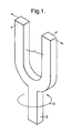
- a known balanced tuning fork configuration is perhaps the most common structural type.
- the fork tines 1 are set into motion 180° out of phase, in the plane of the fork structure.
- the drive is tuned to the resonant frequency of the mode to maximise the amplitude of motion for any given drive level.
- Accurate information the material mechanical properties and control of the dimensional tolerances is necessary to balance the frequencies of the tines 1. This ensures that there is no net force or torque around the centre of mass and reduces sensitivity to linear accelerations.
- An angular rate, ⁇ applied around the axis of a stem 2 at the fork will generate Coriolis forces in the axis orthogonal to the carrier vibration and rotation axes.
- the tines of the fork will exhibit an anti-phase vibration, as shown in Figure 1, at the carrier mode frequency. The amplitude of this vibration will be proportional to the applied rotation rate 3.
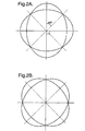
- the resonator structure is actually in motion both radially and tangentially. Usually, only radial motion is detected and thus only this motion is considered in Figure 3 which shows the Coriolis forces acting on a substantially ring-shaped vibrating structure at the anti-nodal points of a Cos 2 ⁇ carrier mode vibration when a rate is applied around the axis normal to the plane of the ring. The velocity vectors (v) at the points of maximum radial motion are marked.
- the diagram shows the extremes of deformation of the resonator vibrating structure 4 from its rest position (5) during the course of a vibration cycle. With no applied rate there will be no response mode motion.
- inertial sensing units which require two or three axes of rate sensing. This may conventionally be achieved by mounting two or three single axis gyros in the required configuration.
- a sensor with inherent multi-axis rate sensing capability would be of great benefit for this and such a device would offer a reduction in size, complexity, component count and assembly time with consequent cost reduction.
- VWOG Vibrating Wheel Gyro
- This design consists of a ring structure centrally supported by four compliant beams.
- the resonant carrier mode is a pendulous rotary motion of the ring. Rotations around the x or y axes in the plane of the ring will set the ring into a rocking motion about the input rotation axis. This motion is detected capacitively by plates located under the ring.
- Such a known device is only capable of operating for two axes rate sensing.
- an improved rate sensor for sensing applied rate on at least two axes and which preferably offers a multi axis rate sensing capability.
- an improved device should be in the form of a single vibrating structure.
- a rate sensor for sensing applied rate on at least two axes, including a vibrating structure, means for vibrating the structure in a Cos 2 ⁇ carrier mode at a Cos 2 ⁇ mode frequency such that rotation about one or other of said at least two axes in the plane of the vibrating structure will generate a Coriolis force sufficient to cause a rocking motion of the vibrating structure about the same axis at a carrier mode frequency, with the vibrating structure having a substantially planar substantially ring or hoop-like form shaped and dimensioned to match the frequencies of the Cos 2 ⁇ mode and rocking mode vibrations in the vibrating structure to give a resonant amplification of the rocking motion, which rocking mode vibration is proportional to the applied rate, and means for detecting the rocking mode vibration and thereby the applied rate.
- the vibrating structure is made of metal or of silicon.
- the vibrating structure is ring like in form having an outer rim supported by a plurality of legs extending substantially radially from a central boss.
- a sensor for sensing applied rate on two axes has a substantially planar ring-like vibrating structure made from metal, wherein the means for vibrating the vibrating structure in a Cos 2 ⁇ mode includes an electromagnetic carrier mode drive element and a capacitive carrier mode pick off element arranged at 0° and 270° respectively with respect to the outer rim of the vibrating structure and located in the plane of the outer rim radially externally thereof adjacent points of maximum radial motion of said rim when vibrating in the Cos 2 ⁇ mode, and wherein the means for detecting the rocking mode vibration includes an x axis electromagnetic drive element, an x axis capacitive pick off element, a y axis electromagnetic drive element and a y axis capacitive pick off element, located adjacent to the outer rim in superimposed relationship therewith at a perpendicular spacing therefrom, with the y axis pick off element, x axis drive element, y axis drive element and x axis pick off element being arranged
- the means for vibrating the vibrating structure additionally includes an electromagnetic response mode drive element and a capacitive response mode pick off element located in the plane of the outer rim of the vibrating structure adjacent to the points of maximum radial movement for the outer rim when vibrating in a response mode, with the response mode drive element and pick off element being arranged at 135° and 225° respectively with respect to the outer rim of the vibrating structure and located in the plane of the outer rim radially externally thereof, to sense rotation about the axis normal to the plane of the vibrating structure.
- the outer rim is substantially circular in plan view or is substantially rectangular in plan view.
- the vibrating structure is made of a nickel-iron alloy.
- a sensor for sensing applied rate on two axes has a substantially planar, substantially ring-like vibrating structure made from silicon wherein the means for vibrating structure in a Cos 2 ⁇ carrier mode includes two electromagnetic carrier mode drive elements and two capacitive carrier mode pick off elements arranged with the drive elements at 0° and 180° and the pick off elements at 90° and 270° respectively with respect to the outer rim of the vibrating structure and located radially externally of the outer rim adjacent points of maximum radial motion of the outer rim when vibrating in the Cos 2 ⁇ mode, and wherein the means for detecting the rocking mode vibration includes an x axis electromagnetic drive element, an x axis capacitive pick off element, a Y axis electromagnetic drive element and a Y axis capacitive pick off element located adjacent the outer rim in superimposed relationship therewith at a perpendicular spacing therefrom, with the y axis drive element, the x axis pick off element, the y axis pick off element, the
- the means for vibrating the vibrating structure additionally includes two electromagnetic z axis response mode drive elements and two capacitive z axis response mode pick off elements located in the plane of the outer rim of the vibrating structure radially externally thereof adjacent points of maximum radial movement for the outer rim when vibrating in a response mode, with the first z axis response mode drive element, the first z axis response mode pick off element, the second z axis response mode drive element and the second z axis response mode pick off element being arranged at 45°, 135°, 225° and 315° respectively around the outer rim of the vibrating structure.
- the outer rim is substantially circular in plan view with the outer rim and legs being suspended above an insulated substrate layer by means of the central boss which is mounted thereon.
- the vibrating structure is dimensioned to match the frequencies of the Cos 2 ⁇ and rocking mode vibration by controlled removal of material from the edge of the outer rim to modify the mass thereof or by controlled removal of material from the neutral axis of the outer rim to modify the stiffness of the outer rim.
- a rate sensor is suitable for sensing applied rate on at least two axes. It includes a vibrating structure 6 and means for vibrating the structure 6 in a Cos 2 ⁇ carrier mode at a Cos 2 ⁇ frequency such that rotation about one or other of said at least two axes in the plane of the structure 6 will generate a Coriolis force sufficient to cause a rocking motion of the vibrating structure 6 about the same axis at the Cos 2 ⁇ carrier mode frequency.
- the vibrating structure 6 has a substantially planar substantially ring or hoop like form shaped and dimensioned to match the frequencies of the Cos 2 ⁇ mode and rocking mode vibrations in the vibrating structure to give a resonant amplification of the rocking motion caused by rotations around one or other of the two axes which rocking mode vibration is proportional to the applied rate.
- the sensor also includes means for detecting the rocking mode vibration and thereby the applied rate.
- the vibrating structure 6 preferably is made of metal or of silicon and preferably is ring like in form having an outer rim 7 supported by a plurality of legs 8 extending substantially radially from a central boss 9.
- the planar ring rim 7 is supported by a multiplicity of compliant legs 8 to allow substantially undamped vibration of the Cos 2 ⁇ mode of the ring rim.
- Conventionally maximum rate sensitivity around the axis normal to the plane of the ring is obtained with the two Cos 2 ⁇ mode frequencies accurately balanced.
- each leg 8 will apply a local perturbation to the mass and stiffness of the ring rim 7.
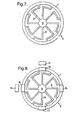
- the resultant of all the individual perturbations to each mode must be balanced. This preferably is achieved using eight legs 8 placed symmetrically around the ring rim 7 as shown in Figure 7 of the accompanying drawings.
- the sensitivity of the ring rim 7 to z-axis rotation is enhanced by matching the carrier and response mode frequencies.
- Finite element modelling of the vibrating structure enables the resonant frequencies of the various ring vibration modes to be calculated.
- the rocking modes also exist as a degenerate pair at a mutual angle of 90°.
- a schematic of the ring rim motion for these modes is shown in Figures 6A and 6B.
- the two extreme points of deformation of the vibrating structure from its rest position 6 are shown together with the direction of motion during each half of the vibration cycle (solid and hatch arrows).
- the dimensions of the vibrating structure 6 according to the present invention and the shape are selected to set the frequency of the rocking modes to match that of the carrier mode. This results in amplification of the rocking mode motion by the Q factor of the structure thus increasing the sensitivity.
- a two or three axis rate sensor according to the present invention requires additional drive and pick-off elements above and/or below the vibrating structure. While this does imply some increase in the size of the device the total volume will be considerably less than would be required for two or three appropriately oriented single axis units.
- An inertial measurement unit using a rate sensor of the present invention requires only a single carrier mode for all axes and thus a single drive circuit.
- the single axis gyro equivalent unit would require three separate drive circuits. These also operate at slightly different frequencies causing possible integration problems. The reduced electronic circuitry requirements will also result in reduced power consumption.
- the vibrating structure in Figure 7 has a ring-like shape as previously described.
- a suitable outer diameter of the vibrating structure rim 7 is 22mm with a rim width of 1mm and a thickness of 1.2mm.
- the structure is made from a Nickel-Iron alloy and operates at a frequency of vibration of substantially 5kHz.
- the structure is designed such that the Cos 2 ⁇ frequency is isolated from all other vibration modes.
- the legs 8 give a compliant support to the ring rim 7 while maintaining sufficient stiffness in the out of plane axis to make the device insensitive to vibrations at lower frequencies.
- the rocking mode resonant frequency is around 2kHz for this structure.
- the vibrating structure design is modified to match the Cos 2 ⁇ and rocking mode frequencies.
- the legs 8 need to be stiffer in comparison to the ring rim 7 and the thickness needs to be increased from the more usual 1.2mm thickness of the known conventional single axis vibrating structure design. This potentially increases the mounting sensitivity of the sensor with a possible reduction of the mechanical Q.
- Suitable dimensions for the vibrating structure ring are 22mm outer diameter, a rim width of 0.5mm, and a thickness of around 2mm.
- the resonant frequencies of interest occur at around 3.1kHz for this vibrating structure design.
- Mechanical tuning is required to achieve accurate balancing of the modes. This may be achieved by the controlled removal of material from the edge of the ring rim 7 or by mass removal at the neutral axis, affecting the stiffness or mass respectively.
- a similar procedure is required to balance the rocking and Cos 2 ⁇ modes.
- the ring rim 7 may be considered as simply a carried mass at the end of the legs 8. Removal of material from the edge of the ring rim 7 will thus reduce this carried mass giving an increase in the resonant frequency.
- the stiffness is reduced leading to a reduction in the frequency.
- the two mode frequencies can thus be differentially shifted enabling them to be brought accurately into balance.
- a rate sensor utilising a vibrating structure 6 as shown in Figure 7, for sensing applied rate on two axes is shown diagrammatically in Figure 8.
- the substantially planar ring-like vibrating structure 8 is made from metal.
- the means for vibrating the structure may be electromagnetic, electrostatic or piezoelectric and the means for detecting movement may be capacitive, electromagnetic, piezoelectric, optical or strain gauge.
- electromagnetic drive elements and capacitive pick off elements are employed.
- a rate sensor for sensing applied rate on two axes has means for vibrating the structure 6 in a Cos 2 ⁇ mode which includes an electromagnetic carrier mode drive element 13 and a capacitive carrier mode pick off element 14 arranged at 0° and 270° respectively with respect to the other rim 7 of the structure 6 and located in the plane of the outer rim 7 radially externally thereto adjacent points of maximum radial motion of the rim 7 when vibrating in the Cos 2 ⁇ mode.
- the means for detecting the rocking mode vibration includes an x axis electromagnetic drive element 15, an x axis capacitive pick off element 16, a y axis electromagnetic drive element 17 and a y axis capacitive pick-off element 18 located adjacent to the outer rim 7 in superimposed relationship therewith at a perpendicular spacing therefrom out of plane with respect to the outer rim 7.
- the y axis pick-off element 18, x axis drive element 15, y axis drive element 17 and x axis pick-off element 16 are arranged at 0°, 90°, 180° and 270° respectively around the outer rim 7.
- the same carrier mode is employed but with a deliberate mismatch between the two cos2 ⁇ mode frequencies.
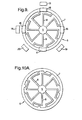
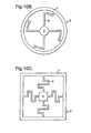
- This mismatch can be built in during the manufacture process by perturbing the mass or stiffness at four equidistant points on the ring rim 7 as shown in Figure 10A.
- a vibration structure design utilising only four support legs 8 as shown in Figure 10B will also split the two Cos 2 ⁇ mode frequencies.
- the use of a non-radially symmetric shape, such as a planar square as shown in Figure 10C capable of sustaining the same basic mode of oscillation is also satisfactory.
- the embodiment of the invention illustrated in Figure 9 is a rate sensor for sensing applied rate on three axes.
- the Cos 2 ⁇ carrier and response mode frequencies must be matched and thus only a vibrating structure such as shown in Figure 7 is suitable.
- the sensor is basically the same as the embodiment of Figure 8 and like parts have been given like reference numbers and will not be further described in detail.
- the means for vibrating the vibrating structure 6 additionally includes an electromagnetic response mode drive element 19 and a capacitive response mode pick-off element 20 located in the plane of the outer rim 7 of the vibrating structure 6 adjacent the points of maximum radial movement for the outer rim 7 when vibrating in a response mode.
- the response mode drive element 19 and pick off element 20 are arranged at 135° and 225° respectively with respect to the outer rim 7 of the vibrating structure 6 and are located in the plane of the outer rim radially externally thereof to sense rotation about the axis normal to the plane of the vibrating structure. Rotation about this latter axis will generate Coriolis forces which cause vibration of the Cos 2 ⁇ response mode in the plane of the rim 7. The amplitude of this vibrator will be proportional to the applied rate.
- the sensor of Figure 9 may be operated in a forced feedback configuration in which the motion detected at the response mode pick-off element 20 is nulled using the response mode drive element 19. Rotation of the sensor about the x axis will induce an oscillation at the x axis pick-off element 16. This motion is nulled using the x axis drive element 15.
- the y axis pick-off element 18 and drive element 17 operate identically. This mode of operation prevents any out of plane motion of the ring rim 7 which might generate noise on the in plane pick-off elements.
- the drive elements 15 and 17 also serve to excite the rocking modes for balancing purposes.
- the sensor of the embodiments of Figures 8 and 9 incorporates a metal vibrating structure 6.
- the sensor may also be manufactured from any material which possesses suitable properties and is capable of being set into resonance and the resulting motion detected as previously set forth.
- An alternative is to manufacture the vibrating structure by micromachining techniques from materials such as crystalline silicon, poly silicon, quartz or metal.
- FIG 11 of the accompanying drawings shows diagrammatically a sensor according to a third embodiment of the present invention using a silicon vibrating structure 6 as previously described in connection with the embodiments of Figures 8 and 9, drive elements may be electromagnetic, electrostatic, piezo, thermal or optical in actuation and the vibrating structure 6 motion may be detected using electrostatic, electromagnetic, piezo or optical techniques.
- Figure 11 shows a two axes rate sensor in silicon using electrostatic drive elements and electrostatic pick-offs.
- the vibrating structure 6 has a substantially planar substantially ring-like shape conveniently having an outer rim 7, legs 8 and a central boss 8 as previously described.
- the structure 6 is located via the boss 9 on an insulating substrate layer 21 which may be made of glass or silicon with an insulating oxide surface layer.
- the vibrating structure 6 is maintained at a fixed voltage with respect to all the conductors which act as the drive and pick-off elements.
- the means for vibrating the vibrating structure 6 in a Cos 2 ⁇ carrier mode includes two electrostatic carrier drive elements 22 and two electrostatic carrier mode pick-off elements 23 arranged with the drive elements 22 at 0° and 180° and the pick-off elements 23 at 90° and 270° respectively with respect to the outer rim 7 of the vibrating structure and located radially externally of the outer rim adjacent the points of maximum radial motion of the rim 7 when vibrating in the Cos 2 ⁇ mode.
- These carrier mode drive elements 22 are used to set the vibrating structure 6 into oscillation.
- the carrier mode pick-off elements 23 which are located at the carrier mode anti-nodal points, sense the radial motion of the vibrating structure 6.
- the means for detecting the rocking mode vibration includes an x axis electrostatic drive element 24, an x axis electrostatic pick-off element 25, a y axis electrostatic drive element 26 and a y axis electrostatic pick-off element 27 located adjacent the outer rim in superimposed relationship therewith at a perpendicular spacing therefrom with the y axis drive element 26, the x axis pick-off element 25, the y axis pick-off element 27 and the x axis drive element 24 being arranged at 0°, 90°, 180° and 270° respectively around the outer rim 7.
- the rocking motion of the x axis rate response mode is detected at the pick-off element 25 located on the surface of the support substrate under the rim 7.
- This motion is nulled using the x axis drive element 24 similarly located under the opposite side of the rim 7.
- the y axis rate response motion is similarly detected by pick-off element 27 and nulled by drive element 26.
- the various drive and pick-off conductive sites are connected, via tracking 28 laid onto the substrate layer surface 21, to bond pads 29.
- the drive and pick-off circuitry is then connected to these bond pads.
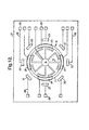
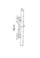
- a cross section of the sensor of Figure 11 is shown in Figure 13. This shows the topography of the in plane and surface conductors more clearly.
- Figure 12 of the accompanying drawings shows in plan a sensor according to a fourth embodiment of the present invention for sensing applied rate on three axes.
- This rate sensor is basically the same as that of Figure 11 and like parts have been given like reference numerals and will not be further described in detail.
- the means for vibrating the vibrating structure 6 additionally includes two electrostatic z axis response mode drive elements 30 and two electrostatic z axis response mode pick-off elements 31 located in the plane of the outer rim 7 of the vibrating structure 6 radially externally thereof adjacent points of maximum radial movement for the outer rim 7 when vibrating in a response mode.
- the first z axis response mode drive element 30, the first z axis response mode pick-off element 31, the second z axis response mode drive element 30 and the second z axis response mode pick-off element 31 are arranged at 45°, 135°, 225° and 315° respectively around the outer rim 7 of the vibrating structure 6.
- the z axis rate response mode motion is detected by the pick-off elements 31.
- Material removal from the vibrating structure 6 to adjust the mass and stiffness in the Figures 11 and 12 embodiments may be carried out using laser ablation techniques. Additionally although the two axis rate sensor of Figure 11 has been shown with an eight leg vibrating structure it may alternatively use vibrating structures having a shape and form corresponding to those of Figures 10A, 10B and 10C.
Landscapes
- Physics & Mathematics (AREA)
- General Physics & Mathematics (AREA)
- Engineering & Computer Science (AREA)
- Radar, Positioning & Navigation (AREA)
- Remote Sensing (AREA)
- Gyroscopes (AREA)
Claims (11)
- Drehgeschwindigkeitssensor zur Feststellung einer um wenigstens zwei Achsen angelegten Drehgeschwindigkeit mit einer Vibrationsstruktur (4, 6) mit Mitteln, um diese Struktur (4, 6) in einem Cos 2 - Trägermodus bei einer Cos 2 -Modenfrequenz derart in Vibration zu versetzen, dass die Drehung um die eine oder andere der wenigstens zwei Achsen (10, 11) in der Ebene der Vibrationsstruktur (4, 6) eine Corioliskraft erzeugt, die ausreicht, um eine Drehschwingungsbewegung in dem Vibrationsaufbau um die gleiche Achse bei der Trägermodenfrequenz zu erzeugen, wobei die Vibrationsstruktur (4, 6) eine im Wesentlichen ringförmige oder reifenförmige Form besitzt, die so gestaltet und dimensioniert ist, dass die Frequenzen des Cos 2 - Modus und der Drehschwingungs-Modenvibrationen in der Vibrationsstruktur eine Resonanzverstärkung der Drehschwingungsbewegung ergeben, wobei die Drehschwingungs-Modenvibration proportional zu der angelegten Drehgeschwindigkeit ist und wobei Mittel vorgesehen sind, um die Drehschwingungs-Modenvibration und demgemäß die angelegte Drehgeschwindigkeit festzustellen.
- Sensor nach Anspruch 1, bei welchem die Vibrationsstruktur (4, 6) aus Metall oder Silizium besteht.
- Sensor nach Anspruch 2, bei welchem die Vibrationsstruktur (4, 6) ringförmig ausgebildet ist und einen äußeren Rand (7) aufweist, der durch mehrere Arme (8) abgestützt wird, welche sich im Wesentlichen radial von einer mittleren Nabe (9) erstrecken.
- Sensor nach Anspruch 3 zur Feststellung einer um zwei Achsen (10, 11) angelegten Drehgeschwindigkeit mit einer im Wesentlichen ebenen ringförmigen Vibrationsstruktur (4, 6) aus Metall, wobei die Mittel zur Vibration der Vibrationsstruktur in einem Cos 2 - Modus ein elektromagnetisches Trägermodus-Antriebselement (13) und ein kapazitives Trägermodus-Abnahmeelement (14) aufweisen, die bei 0° bzw. 270° in Bezug auf den äußeren Rand (7) der Vibrationsstruktur (6) liegen und in einer Ebene des äußeren Randes (7) radial außerhalb desselben in der Nähe der Punkte maximaler radialer Bewegung des Randes (7) bei Vibration im Cos 2 - Modus liegen und wobei die Mittel zur Feststellung der Drehschwingungsvibration ein elektromagnetisches x-Achsen-Antriebselement (15), ein kapazitives x-Achsen-Abnahmeelement (16), ein elektromagnetisches y-Achsen-Antriebselement (17) und ein kapazitives y-Achsen-Abnahmeelement (18) aufweisen, die benachbart zum äußeren Rand (7) über diesem liegend in einem senkrechten Abstand hiervon angeordnet sind, wobei das y-Achsen-Abnahmeetement (18), das x-Achsen-Antriebselement (15), das y-Achsen-Antriebselement (17) und das x-Achsen-Abnahmeelement (16) bei 0°, 90°, 180° bzw. 270° rings um den äußeren Rand (7) herum angeordnet sind.
- Sensor nach Anspruch 4 zur Feststellung einer auf drei Achsen (10,11, 12) angelegten Drehgeschwindigkeit, bei welchem die Mittel zur Vibration der Vibrationsstruktur (6) außerdem ein elektromagnetisches Ansprechmoden-Antriebselement (19) und ein kapazitives Ansprechmoden-Abnahmeelement (20) aufweisen, die in der Ebene des äußeren Randes (7) der Vibrationsstruktur (6) benachbart zu den Punkten maximaler radialer Bewegung des äußeren Randes (7) bei Vibration in einem Ansprechmodus liegen, wobei das Ansprechmoden-Antriebselement (19) und das Abnahmeelement (20) bei 735° bzw. 225° gegenüber dem äußeren Rand (7) der Vibrationsstruktur in der Ebene des äußeren Randes radial außerhalb hiervon liegen, um die Drehung um die Achse normal zur Ebene der Vibrationsstruktur (6) festzustellen.
- Sensor nach Anspruch 3, bei welchem der äußere Rand (7) im Grundriss im Wesentlichen kreisförmig oder im Wesentlichen rechteckig ausgebildet ist.
- Sensor nach einem der Ansprüche 2 bis 6, bei welchem die Vibrationsstruktur (6) aus einer Nickel-Eisen-Legierung besteht.
- Sensor nach Anspruch 3 zur Feststellung einer um zwei Achsen angelegten Drehgeschwindigkeit mit einer im Wesentlichen ebenen im Wesentlichen ringförmigen Vibrationsstruktur (6), die aus Silizium besteht, wobei die Mittel zur Vibration der Vibrationsstruktur in einem Cos 2 - Modus zwei elektrostatische Trägermoden-Antriebselemente (22) und zwei elektrostatische Trägermoden-Abnahmeelemente (23) aufweisen, wobei die Antriebselemente (22) bei 0° und 180° liegen und die Abnahmeelemente (23) bei 90° bzw. 270° gegenüber dem äußeren Rand (7) der Vibrationsstruktur (6), und zwar radial außerhalb des äußeren Randes benachbart zu den Punkten maximaler radialer Bewegung des äußeren Randes, wenn dieser in dem Cos 2 - Modus vibriert, und wobei die Mittel zur Feststellung der Drehschwingungsvibration ein elektrostatisches x-Achsen-Antriebselement (24), ein elektrostatisches x-Achsen-Abnahmeelement (25), ein elektrostatisches y-Achsen-Antriebselement (26) und ein elektrostatisches y-Achsen-Abnahmeelement (27) aufweisen, die um den äußeren Rand (7) über diesem in einem senkrechten Abstand angeordnet sind, wobei das y-Achsen-Antriebselement (26), das x-Achsen-Abnahmeelement (25), das y-Achsen-Abnahmeelement (27) und das x-Achsen-Antriebselement (24) bei 0°, 90°, 180° bzw. 270° relativ zum Außenrand (7) angeordnet sind.
- Sensor nach Anspruch 8 zur Feststellung einer um drei Achsen herum angelegten Drehgeschwindigkeit, bei welcher die Mittel zur Vibration der Vibrationsstruktur (6) außerdem zwei elektrostatische z-Achsen-Ansprechmoden-Antriebselemente (30) und zwei elektrostatische z-Achsen-Ansprechmoden-Abnahmeelemente (31) aufweisen, die in der Ebene des äußeren Randes (7) der Vibrationsstruktur (6) radial außerhalb von dieser benachbart zu Punkten maximaler radialer Bewegung für den äußeren Rand liegen, wenn dieser in einem Ansprechmodus vibriert, wobei das erste z-Achsen-Ansprechmoden-Antriebselement (30), das erste z-Achsen-Ansprechmoden-Abnahmeelement (31), das zweite z-Achsen-Ansprechmoden-Antriebselement (30) und das zweite z-Achsen-Ansprechmoden-Abnahmeelement (31) bei 45°, 135°, 225° und 315° um den äußeren Rand (7) der Vibrationsstruktur (6) herum angeordnet sind.
- Sensor nach Anspruch 9, bei welchem der äußere Rand (7) im Grundriss im Wesentlichen kreisförmig ist, wobei der äußere Rand und die Arme (8) über einer isolierenden Substratschicht angeordnet sind, auf der sie mit der zentralen Nabe (9) montiert sind.
- Sensor nach einem der Ansprüche 3 bis 10, bei welchem die Vibrationsstruktur (6) so dimensioniert ist, dass sie den Frequenzen der Cos 2 -Modenvibrationen und der Drehschwingungs-Modenvibrationen angepasst ist, indem eine bestimmte Materialmenge vom Rand des äußeren Randes (7) abgenommen wird, um dessen Masse zu verändern oder indem eine bestimmte Materialmenge von der neutralen Achse des äußeren Randes abgenommen wird, um die Steifheit des äußeren Randes (7) zu modifizieren.
Applications Claiming Priority (2)
| Application Number | Priority Date | Filing Date | Title |
|---|---|---|---|
| GB9620982A GB2318184B (en) | 1996-10-08 | 1996-10-08 | A rate sensor |
| GB9620982 | 1996-10-08 |
Publications (3)
| Publication Number | Publication Date |
|---|---|
| EP0836073A2 EP0836073A2 (de) | 1998-04-15 |
| EP0836073A3 EP0836073A3 (de) | 1999-07-28 |
| EP0836073B1 true EP0836073B1 (de) | 2004-02-25 |
Family
ID=10801121
Family Applications (1)
| Application Number | Title | Priority Date | Filing Date |
|---|---|---|---|
| EP97203115A Expired - Lifetime EP0836073B1 (de) | 1996-10-08 | 1997-10-07 | Drehgeschwindigkeitssensor |
Country Status (7)
| Country | Link |
|---|---|
| US (1) | US5915276A (de) |
| EP (1) | EP0836073B1 (de) |
| JP (1) | JP3834397B2 (de) |
| KR (1) | KR100486129B1 (de) |
| CA (1) | CA2217683C (de) |
| DE (1) | DE69727756T2 (de) |
| GB (1) | GB2318184B (de) |
Families Citing this family (47)
| Publication number | Priority date | Publication date | Assignee | Title |
|---|---|---|---|---|
| GB2338781B (en) * | 1998-03-14 | 2002-04-03 | British Aerospace | A gyroscope |
| GB2335273B (en) | 1998-03-14 | 2002-02-27 | British Aerospace | A two axis gyroscope |
| JP2000009473A (ja) | 1998-06-22 | 2000-01-14 | Tokai Rika Co Ltd | 2軸ヨーレートセンサ及びその製造方法 |
| GB9817347D0 (en) * | 1998-08-11 | 1998-10-07 | British Aerospace | An angular rate sensor |
| US6198387B1 (en) | 1998-11-09 | 2001-03-06 | Delphi Technologies, Inc. | Restraint deployment control with central and frontal crash sensing |
| JP3796991B2 (ja) * | 1998-12-10 | 2006-07-12 | 株式会社デンソー | 角速度センサ |
| US6128954A (en) * | 1998-12-18 | 2000-10-10 | Delco Electronics Corporation | Spring for a resonance ring of an angular rate sensor |
| US6305222B1 (en) * | 1999-05-27 | 2001-10-23 | Delphi Technologies, Inc. | Road vibration compensated angular rate sensor |
| US6158282A (en) * | 1999-07-07 | 2000-12-12 | Litton Systems Inc. | Extraction of double-oscillation-frequency sinusoids in vibratory rotation sensors |
| DE19938206A1 (de) * | 1999-08-12 | 2001-02-15 | Bosch Gmbh Robert | Mikromechanischer Drehbeschleunigungssensor |
| DE19945859A1 (de) * | 1999-09-24 | 2001-03-29 | Bosch Gmbh Robert | Mikromechanischer Drehratensensor |
| US6189382B1 (en) * | 1999-11-05 | 2001-02-20 | Litton Systems, Inc. | Vibratory sensor with self-calibration and low noise digital conversion |
| GB0001294D0 (en) * | 2000-01-20 | 2000-03-08 | British Aerospace | Multi-axis sensing device |
| GB0001775D0 (en) * | 2000-01-27 | 2000-03-22 | British Aerospace | Improvements relating to angular rate sensor devices |
| FR2821422B1 (fr) * | 2001-02-23 | 2003-05-23 | Sagem | Resonateur mecanique planaire sensible selon un axe perpendiculaire a son plan |
| GB0122254D0 (en) | 2001-09-14 | 2001-11-07 | Bae Systems Plc | Vibratory gyroscopic rate sensor |
| GB0122253D0 (en) | 2001-09-14 | 2001-11-07 | Bae Systems Plc | Vibratory gyroscopic rate sensor |
| GB0122256D0 (en) | 2001-09-14 | 2001-11-07 | Bae Systems Plc | Vibratory gyroscopic rate sensor |
| GB0122258D0 (en) * | 2001-09-14 | 2001-11-07 | Bae Systems Plc | Vibratory gyroscopic rate sensor |
| GB0122252D0 (en) * | 2001-09-14 | 2001-11-07 | Bae Systems Plc | Vibratory gyroscopic rate sensor |
| TWI220155B (en) * | 2003-07-25 | 2004-08-11 | Ind Tech Res Inst | Micro vibratory dual-axis sensitive gyroscope |
| CN100483073C (zh) * | 2003-08-05 | 2009-04-29 | 财团法人工业技术研究院 | 微型振动式双轴感测陀螺仪 |
| US20050062362A1 (en) * | 2003-08-28 | 2005-03-24 | Hongyuan Yang | Oscillatory gyroscope |
| FR2863709B1 (fr) * | 2003-12-11 | 2006-02-17 | Sagem | Capteur de rotation inertiel a traitement isotrope |
| JP2006064539A (ja) * | 2004-08-26 | 2006-03-09 | Matsushita Electric Works Ltd | ジャイロセンサおよび角速度検出方法 |
| US7426860B2 (en) * | 2005-08-08 | 2008-09-23 | Litton Systems Inc. | Ring resonator gyro with folded cylinder suspension |
| US20090064783A1 (en) | 2006-01-24 | 2009-03-12 | Matsushita Electric Industrial Co., Ltd. | Inertial force sensor |
| JP5036218B2 (ja) * | 2006-05-29 | 2012-09-26 | 住友精密工業株式会社 | 角速度センサ |
| DE102007051591B4 (de) | 2007-10-12 | 2019-04-25 | Robert Bosch Gmbh | Mikromechanische Vorrichtung mit Antriebsrahmen |
| EP2210060A1 (de) * | 2007-11-08 | 2010-07-28 | Robert Bosch GmbH | Drehratensensor mit zwei sensitiven achsen |
| FR2932563B1 (fr) * | 2008-06-13 | 2010-06-18 | Sagem Defense Securite | Capteur de rotation inertiel a derive compensee. |
| WO2011086633A1 (ja) * | 2010-01-12 | 2011-07-21 | ソニー株式会社 | 角速度センサ、電子機器及び角速度の検出方法 |
| FR2958030B1 (fr) * | 2010-03-23 | 2012-04-20 | Sagem Defense Securite | Procede et dispositif de mesure angulaire avec compensation de non linearites |
| JP5652112B2 (ja) * | 2010-10-18 | 2015-01-14 | セイコーエプソン株式会社 | 物理量センサーおよび電子機器 |
| US9091544B2 (en) * | 2010-11-05 | 2015-07-28 | Analog Devices, Inc. | XY-axis shell-type gyroscopes with reduced cross-talk sensitivity and/or mode matching |
| US20140260611A1 (en) * | 2013-03-15 | 2014-09-18 | Analog Devices, Inc. | XY-Axis Gyroscopes with Electrode Configuration for Detecting Quadrature Errors and Out-of-Plane Sense Modes |
| US9599471B2 (en) * | 2013-11-14 | 2017-03-21 | Analog Devices, Inc. | Dual use of a ring structure as gyroscope and accelerometer |
| US9709595B2 (en) | 2013-11-14 | 2017-07-18 | Analog Devices, Inc. | Method and apparatus for detecting linear and rotational movement |
| US10746548B2 (en) | 2014-11-04 | 2020-08-18 | Analog Devices, Inc. | Ring gyroscope structural features |
| US9869552B2 (en) * | 2015-03-20 | 2018-01-16 | Analog Devices, Inc. | Gyroscope that compensates for fluctuations in sensitivity |
| CN106224480B (zh) * | 2016-08-08 | 2018-07-20 | 太原理工大学 | 一种基于四杆机构的大行程柔性旋转铰 |
| JP6801492B2 (ja) * | 2017-02-15 | 2020-12-16 | セイコーエプソン株式会社 | ジャイロセンサー、電子機器、および移動体 |
| GB2565298B (en) * | 2017-08-07 | 2022-03-16 | Atlantic Inertial Systems Ltd | Angular rate sensors |
| US10655964B2 (en) * | 2017-08-08 | 2020-05-19 | Hrl Laboratories, Llc | High quality factor MEMS silicon flower-of-life vibratory gyroscope |
| US11656077B2 (en) | 2019-01-31 | 2023-05-23 | Analog Devices, Inc. | Pseudo-extensional mode MEMS ring gyroscope |
| US11346668B2 (en) * | 2019-12-12 | 2022-05-31 | Enertia Microsystems Inc. | System and method for micro-scale machining |
| JP2024096569A (ja) * | 2023-01-04 | 2024-07-17 | 株式会社東芝 | センサ及び電子装置 |
Family Cites Families (7)
| Publication number | Priority date | Publication date | Assignee | Title |
|---|---|---|---|---|
| DE69102590T2 (de) * | 1990-05-18 | 1994-10-06 | British Aerospace | Trägheitssensoren. |
| US5540094A (en) * | 1990-12-22 | 1996-07-30 | British Aerospace Public Limited Company | Scale factor compensation for piezo-electric rate sensors |
| GB9207148D0 (en) * | 1992-04-01 | 1992-05-13 | British Aerospace | Planar rate sensor |
| US5555765A (en) * | 1993-02-10 | 1996-09-17 | The Charles Stark Draper Laboratory, Inc. | Gimballed vibrating wheel gyroscope |
| JPH06242135A (ja) * | 1993-02-12 | 1994-09-02 | Aisin Seiki Co Ltd | 角速度センサの駆動回路 |
| JP3453724B2 (ja) * | 1994-06-03 | 2003-10-06 | アイシン精機株式会社 | 角速度検出装置 |
| GB2299669B (en) * | 1995-04-07 | 1998-12-16 | British Aerospace | Method for actively balancing a vibrating structure gyroscope sensing element structure |
-
1996
- 1996-10-08 GB GB9620982A patent/GB2318184B/en not_active Expired - Fee Related
-
1997
- 1997-10-07 DE DE69727756T patent/DE69727756T2/de not_active Expired - Lifetime
- 1997-10-07 EP EP97203115A patent/EP0836073B1/de not_active Expired - Lifetime
- 1997-10-07 CA CA002217683A patent/CA2217683C/en not_active Expired - Fee Related
- 1997-10-08 JP JP27585297A patent/JP3834397B2/ja not_active Expired - Fee Related
- 1997-10-08 KR KR1019970051558A patent/KR100486129B1/ko not_active Expired - Fee Related
- 1997-10-08 US US08/946,830 patent/US5915276A/en not_active Expired - Lifetime
Also Published As
| Publication number | Publication date |
|---|---|
| JPH10160483A (ja) | 1998-06-19 |
| EP0836073A3 (de) | 1999-07-28 |
| US5915276A (en) | 1999-06-22 |
| KR19980032646A (ko) | 1998-07-25 |
| JP3834397B2 (ja) | 2006-10-18 |
| GB2318184A (en) | 1998-04-15 |
| CA2217683A1 (en) | 1998-04-08 |
| GB9620982D0 (en) | 1996-11-27 |
| CA2217683C (en) | 2001-02-20 |
| GB2318184B (en) | 2000-07-05 |
| EP0836073A2 (de) | 1998-04-15 |
| DE69727756D1 (de) | 2004-04-01 |
| KR100486129B1 (ko) | 2005-08-31 |
| DE69727756T2 (de) | 2004-07-29 |
Similar Documents
| Publication | Publication Date | Title |
|---|---|---|
| EP0836073B1 (de) | Drehgeschwindigkeitssensor | |
| KR100511845B1 (ko) | 자이로스코프 | |
| US6282958B1 (en) | Angular rate sensor | |
| US6990863B2 (en) | Isolated resonator gyroscope with isolation trimming using a secondary element | |
| EP1064519B1 (de) | Zweiachsiger kreisel | |
| US20040118204A1 (en) | Vibratory gyroscopic rate sensor | |
| US20040118205A1 (en) | Vibratory gyroscopic rate sensor |
Legal Events
| Date | Code | Title | Description |
|---|---|---|---|
| PUAI | Public reference made under article 153(3) epc to a published international application that has entered the european phase |
Free format text: ORIGINAL CODE: 0009012 |
|
| AK | Designated contracting states |
Kind code of ref document: A2 Designated state(s): DE FR GB IT SE |
|
| AX | Request for extension of the european patent |
Free format text: AL;LT;LV;RO;SI |
|
| PUAL | Search report despatched |
Free format text: ORIGINAL CODE: 0009013 |
|
| AK | Designated contracting states |
Kind code of ref document: A3 Designated state(s): AT BE CH DE DK ES FI FR GB GR IE IT LI LU MC NL PT SE |
|
| AX | Request for extension of the european patent |
Free format text: AL;LT;LV;RO;SI |
|
| 17P | Request for examination filed |
Effective date: 19991123 |
|
| AKX | Designation fees paid |
Free format text: DE FR GB IT SE |
|
| RAP1 | Party data changed (applicant data changed or rights of an application transferred) |
Owner name: BAE SYSTEMS PLC |
|
| GRAP | Despatch of communication of intention to grant a patent |
Free format text: ORIGINAL CODE: EPIDOSNIGR1 |
|
| GRAS | Grant fee paid |
Free format text: ORIGINAL CODE: EPIDOSNIGR3 |
|
| GRAA | (expected) grant |
Free format text: ORIGINAL CODE: 0009210 |
|
| AK | Designated contracting states |
Kind code of ref document: B1 Designated state(s): DE FR GB IT SE |
|
| REG | Reference to a national code |
Ref country code: GB Ref legal event code: FG4D |
|
| REG | Reference to a national code |
Ref country code: SE Ref legal event code: TRGR |
|
| REF | Corresponds to: |
Ref document number: 69727756 Country of ref document: DE Date of ref document: 20040401 Kind code of ref document: P |
|
| PGFP | Annual fee paid to national office [announced via postgrant information from national office to epo] |
Ref country code: SE Payment date: 20040923 Year of fee payment: 8 |
|
| ET | Fr: translation filed | ||
| PLBE | No opposition filed within time limit |
Free format text: ORIGINAL CODE: 0009261 |
|
| STAA | Information on the status of an ep patent application or granted ep patent |
Free format text: STATUS: NO OPPOSITION FILED WITHIN TIME LIMIT |
|
| 26N | No opposition filed |
Effective date: 20041126 |
|
| PG25 | Lapsed in a contracting state [announced via postgrant information from national office to epo] |
Ref country code: SE Free format text: LAPSE BECAUSE OF NON-PAYMENT OF DUE FEES Effective date: 20051008 |
|
| EUG | Se: european patent has lapsed | ||
| REG | Reference to a national code |
Ref country code: GB Ref legal event code: 732E |
|
| REG | Reference to a national code |
Ref country code: FR Ref legal event code: TP |
|
| PGFP | Annual fee paid to national office [announced via postgrant information from national office to epo] |
Ref country code: DE Payment date: 20091026 Year of fee payment: 13 |
|
| PGFP | Annual fee paid to national office [announced via postgrant information from national office to epo] |
Ref country code: IT Payment date: 20101026 Year of fee payment: 14 |
|
| REG | Reference to a national code |
Ref country code: DE Ref legal event code: R119 Ref document number: 69727756 Country of ref document: DE Effective date: 20110502 |
|
| PGFP | Annual fee paid to national office [announced via postgrant information from national office to epo] |
Ref country code: FR Payment date: 20111103 Year of fee payment: 15 |
|
| PG25 | Lapsed in a contracting state [announced via postgrant information from national office to epo] |
Ref country code: IT Free format text: LAPSE BECAUSE OF NON-PAYMENT OF DUE FEES Effective date: 20111007 |
|
| PG25 | Lapsed in a contracting state [announced via postgrant information from national office to epo] |
Ref country code: DE Free format text: LAPSE BECAUSE OF NON-PAYMENT OF DUE FEES Effective date: 20110502 |
|
| REG | Reference to a national code |
Ref country code: FR Ref legal event code: ST Effective date: 20130628 |
|
| PG25 | Lapsed in a contracting state [announced via postgrant information from national office to epo] |
Ref country code: FR Free format text: LAPSE BECAUSE OF NON-PAYMENT OF DUE FEES Effective date: 20121031 |
|
| PGFP | Annual fee paid to national office [announced via postgrant information from national office to epo] |
Ref country code: GB Payment date: 20131002 Year of fee payment: 17 |
|
| GBPC | Gb: european patent ceased through non-payment of renewal fee |
Effective date: 20141007 |
|
| PG25 | Lapsed in a contracting state [announced via postgrant information from national office to epo] |
Ref country code: GB Free format text: LAPSE BECAUSE OF NON-PAYMENT OF DUE FEES Effective date: 20141007 |