EP0836079A1 - Drehkodierer - Google Patents
Drehkodierer Download PDFInfo
- Publication number
- EP0836079A1 EP0836079A1 EP97117580A EP97117580A EP0836079A1 EP 0836079 A1 EP0836079 A1 EP 0836079A1 EP 97117580 A EP97117580 A EP 97117580A EP 97117580 A EP97117580 A EP 97117580A EP 0836079 A1 EP0836079 A1 EP 0836079A1
- Authority
- EP
- European Patent Office
- Prior art keywords
- housing
- base plate
- encoder according
- motor shaft
- guide
- Prior art date
- Legal status (The legal status is an assumption and is not a legal conclusion. Google has not performed a legal analysis and makes no representation as to the accuracy of the status listed.)
- Granted
Links
Images


Classifications
-
- G—PHYSICS
- G01—MEASURING; TESTING
- G01D—MEASURING NOT SPECIALLY ADAPTED FOR A SPECIFIC VARIABLE; ARRANGEMENTS FOR MEASURING TWO OR MORE VARIABLES NOT COVERED IN A SINGLE OTHER SUBCLASS; TARIFF METERING APPARATUS; MEASURING OR TESTING NOT OTHERWISE PROVIDED FOR
- G01D11/00—Component parts of measuring arrangements not specially adapted for a specific variable
- G01D11/24—Housings ; Casings for instruments
- G01D11/245—Housings for sensors
-
- H—ELECTRICITY
- H02—GENERATION; CONVERSION OR DISTRIBUTION OF ELECTRIC POWER
- H02K—DYNAMO-ELECTRIC MACHINES
- H02K11/00—Structural association of dynamo-electric machines with electric components or with devices for shielding, monitoring or protection
- H02K11/20—Structural association of dynamo-electric machines with electric components or with devices for shielding, monitoring or protection for measuring, monitoring, testing, protecting or switching
- H02K11/21—Devices for sensing speed or position, or actuated thereby
-
- H—ELECTRICITY
- H02—GENERATION; CONVERSION OR DISTRIBUTION OF ELECTRIC POWER
- H02K—DYNAMO-ELECTRIC MACHINES
- H02K11/00—Structural association of dynamo-electric machines with electric components or with devices for shielding, monitoring or protection
- H02K11/20—Structural association of dynamo-electric machines with electric components or with devices for shielding, monitoring or protection for measuring, monitoring, testing, protecting or switching
- H02K11/21—Devices for sensing speed or position, or actuated thereby
- H02K11/22—Optical devices
-
- H—ELECTRICITY
- H02—GENERATION; CONVERSION OR DISTRIBUTION OF ELECTRIC POWER
- H02K—DYNAMO-ELECTRIC MACHINES
- H02K11/00—Structural association of dynamo-electric machines with electric components or with devices for shielding, monitoring or protection
- H02K11/30—Structural association with control circuits or drive circuits
- H02K11/33—Drive circuits, e.g. power electronics
Definitions
- the invention relates to an encoder connected to a motor, the one with a reflection sensor, a clock disc and a circuit board.
- the circuit board contains all components required for the operation of the sensor, such as Resistor and contact bar.
- the reflection sensor is together with a clock disc that to be aligned axially on the motor shaft, in housed in a housing.
- the housing is on the shaft exit side of the engine flanged.
- a well-known type of encoder is in the HP manual on page 1 to 70.
- a base plate is attached there for mounting screwed the flange plane of the motor and then the timing disk precisely aligned on the shaft using an adjusting device.
- the housing is pressed onto the base plate from above and fixed by clip cams.
- the clock disk is mounted in the housing, with a lock with a large diameter is used.
- the well-known encoder must be locked from the top of the housing be accessible so that the housing cover is large enough should be chosen. As a result, the sensor can only move relatively far from the center of the clock disc.
- the housing dimensions are in Width and height significantly larger than they are due to the individual elements should be. It has also proven to be disadvantageous that considerable time and special tools for assembly and adjustment are needed. In addition, the assembly result is not always satisfactory, so that under unfavorable circumstances a Readjustment is required.
- the object of the present invention is therefore to overcome these disadvantages through a simple and production-oriented construction of the mini encoder to improve the dimensions by approx. 50% should be reduced compared to the previous model.
- the new mini encoder consists of 2 separate modules, whereby the reflection sensor together with the clock disc by means of a Lock washer is pre-assembled in the housing while the base plate is formed with adjusting and fixing elements.
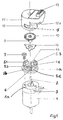
- Figure 1 shows the overall structure in an exploded view.
- Figure 2 shows the housing with all internals and one Part of the base plate in cross section.
- Figures 3a and 3b show the function of the bayonet segments in Side view.
- a motor 1 is in a vertical position with an upward protruding motor shaft 2 and with laterally led out Power connections 3 shown.
- a base plate 4 which in the axial direction on the upper side designed as a flange level the motor 1 is screwed on.
- the base plate 4 On the base plate 4 are bayonet segments arranged in a ring 5 attached.
- the bayonet locking elements are symmetrical distributed around the circumference and rise in the radial direction on the outer ring surface of the segments to the periphery of the Flange level 4a of the base plate 4.
- the Base plate 4 and mounting holes 4b for the screws 7 and a central bore 4c and guide surfaces 4d, which over the circumference of the base plate distributed on the outer surfaces of the Bayonet segments 5 are arranged.
- the motor shaft 2 When attaching the base plate 4 on the motor face 1a the motor shaft 2 is inserted through the central bore 4c and attached by screws.
- the motor shaft 2 preferably has a chamfer or rounding at its tip so that the motor shaft 2 lightly into the bore of a hub hub 9 can be introduced.
- FIG 2 is the pre-assembled housing unit with all internals shown. These consist of a hub 9 held clock 10, which by a retaining ring 14 in Housing is secured against falling out. This is the transportation the pre-assembled module without any problems and without special Transport bracket possible.
- a hub 9 held clock 10 which by a retaining ring 14 in Housing is secured against falling out.
- This is the transportation the pre-assembled module without any problems and without special Transport bracket possible.
- This centering surface 17 is for this determines a self-centering in connection with the To effect guide surface of the housing.
- a countersunk surface may be arranged at the end of the hub 9, e.g. in shape a conical depression or a catch hole 9a.
- the optical sensor 8 is in the housing 11 housed, with electrical on the top of the housing Connections 13 in the form of a plug connector are available.
- a Circuit board 8a forms the connections for the LED and the optical Sensor.
- the slots 12 are trapezoidal and have one upper inclined surface 12a, which with an inclined surface 5a Bayonet segments correspond.
- the clock disc holder and thus the clock disc 10 is through a locking ring 14 against unintentional falling out secured to the housing 11.
- the locking ring ensures 14 that sufficient play for centering the Clock disk 10 is present on the motor shaft.
- the clock disk holder has on its facing the engine End of a catch hole 9a, with which the vertical axes of Shaft and timing disk can be brought into a line.
- a centering and a fixed connection e.g. by Pressing. This can advantageously be done by that the narrowed hub is slotted and thereby a press fit between the hub and the motor shaft even at low Contact forces is effected.
- the housing is from the connection side rotated clockwise according to FIG. 1, whereby through the inclined surfaces 5a of the bayonet segments 5 and the inclined surfaces 12a of the housing 11 raise the housing, as shown in Fig. 3a, 6 takes place.
- the resulting one Gap S ensures that the surface 17 of the hub is released becomes.
- the housing is distributed along the circumference Screen marks 15 via corresponding counter-screens 6 on the Base plate 4 fixed.
Landscapes
- Engineering & Computer Science (AREA)
- Microelectronics & Electronic Packaging (AREA)
- Power Engineering (AREA)
- Physics & Mathematics (AREA)
- General Physics & Mathematics (AREA)
- Transmission And Conversion Of Sensor Element Output (AREA)
- Optical Transform (AREA)
Abstract
Description
Claims (9)
- Encoder mit teilbarem Gehäuse zum stirnseitigen Anflanschen an einen Motor (1), der zumindest an der Flanschebene eine in das Gehäuse hineinragende Motorwelle (2) aufweist,wobei in dem Gehäuse ein Sensor, eine Leiterplatte und eine Taktscheibe (10) untergebracht sind undwobei die Taktscheibendrehachse zentrisch auf der Motorwelle justiert ist,
dadurch gekennzeichnet,daß das Gehäuse aus einer Grundplatte (4) und einem Gehäuseoberteil (11) besteht, die ineinander steckbar sind,daß auf der Grundplatte (4) ringförmige Bajonettsegemente (5) angeordnet sind,die in entsprechende Aussparungen (12) des Gehäuseoberteils eingreifen,daß an oder in der Nähe des Außenrandes der Grundplatte (4) Führungsflächen (5b) ausgebildet sind, die mit entsprechenden Gegenflächen am Gehäuseoberteil eine Gleitführung bilden und die beim Einstecken durch Drehung in Umfangsrichtung zusammenwirken,und daß in einer Dachfläche des Gehäuseoberteils konzentrisch zur Motorwelle ein Anpreßring (16) für die Justierung der Taktscheibe (10) auf der Motorwelle (2) ausgebildet ist. - Encoder nach Anspruch 1,
dadurch gekennzeichnet,daß die Führungsflächen (5b) als Teil der Bajonettsegemente (5) auf der Grundplatte (4) angeordnet sind. - Encoder nach einem der vorhergehenden Ansprüche,
dadurch gekennzeichnet,daß die Taktscheibe (10) eine Nabe (9) aufweist, in die eine zur Dachfläche des Gehäuseoberteils aus der Taktscheibenebene herausragende Gegenpreßfläche (17) eingeformt ist und daß die zur Motorwelle (2) hinweisende Seite der Naben als Führungsschaft ausgebildet ist. - Encoder nach einem der vorhergehenden Ansprüche,
dadurch gekennzeichnet,daß am Austrittsende des Führungsschaftes eine Fangbohrung für das Einfangen der Motorwelle angeordnet ist. - Encoder nach einem der vorhergehenden Ansprüche,
dadurch gekennezeichnet,daß am inneren Gehäuseumfang Rastermarken (15) und an den entsprechenden Umfangsseiten der Grundplatte Gegenrasterungen (6) zur Fixierung der Gehäuseteile angeordnet sind. - Encoder nach einem der vorhergehenden Ansprüche,
dadurch gekennzeichnet,daß die Rastermarken und die Gegenrasterungen sägezahnförmig ausgebildet sind. - Encoder nach einem der vorhergehenden Ansprüche,
dadurch gekennzeichnet,daß die Bajonettsegmente (5) eine im wesentlichen parallel zur Flanschebene verlaufende Kontaktfläche und eine schräg zur Grundplattenebene verlaufende Leitfläche (5a) aufweisen und daß im Gehäuseoberteil eine entsprechend geneigte Gegenleitfläche (12a) in den Aussparungen (12) ausgebildet ist,wobei die Gegenleitfläche (12a) gegenüber der Leitfläche verlängert istund daß bei einer Drehbewegung des Gehäuseoberteils um die Taktscheibenachse die Gegenfläche (12a) auf der Leitfläche (5a) der Bajonettsegmente (5) in Achsrichtung von der Grundplatte weg beweglich ist. - Encoder nach einem der vorhergehenden Ansprüche,
dadurch gekennzeichnet,daß die Taktscheibe im Gehäuseoberteil durch einen Sicherungsring (14) mit Spiel gehalten wird. - Encoder nach einem der vorhergehenden Ansprüche,
dadurch gekennzeichnet,daß der Sicherungsring (14) radiale Verlängerungen aufweist, die im Gehäuseoberteil verklammert sindund daß in der Mittelbohrung des Sicherungsringes die Taktscheibennabe mit Spiel gehalten wird.
Applications Claiming Priority (2)
| Application Number | Priority Date | Filing Date | Title |
|---|---|---|---|
| DE19641929 | 1996-10-11 | ||
| DE19641929A DE19641929C2 (de) | 1996-10-11 | 1996-10-11 | Encoder |
Publications (2)
| Publication Number | Publication Date |
|---|---|
| EP0836079A1 true EP0836079A1 (de) | 1998-04-15 |
| EP0836079B1 EP0836079B1 (de) | 2001-08-22 |
Family
ID=7808449
Family Applications (1)
| Application Number | Title | Priority Date | Filing Date |
|---|---|---|---|
| EP97117580A Expired - Lifetime EP0836079B1 (de) | 1996-10-11 | 1997-10-10 | Drehkodierer |
Country Status (4)
| Country | Link |
|---|---|
| US (1) | US5859425A (de) |
| EP (1) | EP0836079B1 (de) |
| JP (1) | JP3137913B2 (de) |
| DE (2) | DE19641929C2 (de) |
Cited By (7)
| Publication number | Priority date | Publication date | Assignee | Title |
|---|---|---|---|---|
| EP1767906A3 (de) * | 2005-09-26 | 2008-06-18 | Pwb-Ruhlatec Industrieprodukte GmbH | Selbstzentrierende Nabe |
| EP1621854A3 (de) * | 2004-07-29 | 2012-06-13 | PWB encoders GmbH | Encoderbaugruppe und Verfahren zu ihrer Montage |
| WO2012112225A1 (en) * | 2011-02-16 | 2012-08-23 | Tyco Electronics Corporation | Sensor subsystem for a lighting assembly |
| EP1617184A3 (de) * | 2004-06-18 | 2013-05-22 | Alps Electric Co., Ltd. | Trager fur Rotationsorgan und Rotationsdetektor |
| EP2584677A3 (de) * | 2011-10-17 | 2015-11-11 | Dunkermotoren GmbH | Drehwinkelgeber für einen Elektromotor, Elektromotor und Verfahren zum Herstellen eines solchen Drehwinkelgebers |
| CN105363790A (zh) * | 2015-12-07 | 2016-03-02 | 天津市新宇彩板有限公司 | 轧机电机编码器固定装置 |
| CN106370149A (zh) * | 2016-11-16 | 2017-02-01 | 江西昌河汽车有限责任公司 | 发动机正时角度测量装置及检测方法 |
Families Citing this family (35)
| Publication number | Priority date | Publication date | Assignee | Title |
|---|---|---|---|---|
| DE19860107B4 (de) * | 1998-12-23 | 2011-03-10 | Pwb Encoders Gmbh | Taktscheibenträger |
| DE19860012A1 (de) | 1998-12-23 | 2000-06-29 | Pwb Ruhlatec Ind Prod Gmbh | Selbstzentrierende Taktscheibennabe und Verfahren zu ihrer Montage |
| DE19923900B4 (de) | 1999-05-25 | 2009-11-26 | Pwb-Ruhlatec Industrieprodukte Gmbh | Encoder mit zusammensteckbarem Gehäuse |
| US6552464B1 (en) * | 1999-11-09 | 2003-04-22 | Siemens Canada Limited | Totally integrated engine cooling module for DC motors |
| DE10016959B4 (de) * | 2000-04-06 | 2006-12-14 | Pwb-Ruhlatec Industrieprodukte Gmbh | Vorrichtung zum Positionieren von gradlinig oder rotierend bewegten Maschinenteilen |
| US6624407B1 (en) | 2001-07-03 | 2003-09-23 | Lexmark International, Inc. | Encoder with mask spacer contacting the encoder film |
| US6600151B2 (en) | 2001-09-19 | 2003-07-29 | Lexmark International, Inc. | Optical encoder assembly with non-engageable encoder housing and receiver plate comprising a through hole and window |
| DE10332167A1 (de) * | 2003-07-15 | 2005-02-10 | Pwb-Ruhlatec Industrieprodukte Gmbh | Encodersystem und Verfahren zur Montage eines Encodersystems |
| DE10356224A1 (de) | 2003-12-02 | 2005-06-30 | Pwb-Ruhlatec Industrieprodukte Gmbh | Taktscheibenbefestigung |
| DE102004044890A1 (de) * | 2004-09-14 | 2006-03-30 | Endress + Hauser Gmbh + Co. Kg | Vorrichtung zur Bestimmung und/oder Überwachung mindestens einer Prozessgröße eines Mediums |
| DE102004060864A1 (de) * | 2004-12-17 | 2006-06-22 | Dr. Johannes Heidenhain Gmbh | Winkelmesseinrichtung |
| US20060187573A1 (en) * | 2005-02-24 | 2006-08-24 | Electro-Sensors, Inc. | Sensor equipment guard |
| US7470889B2 (en) * | 2005-06-02 | 2008-12-30 | Renco Encoders, Inc. | Servo cleat for an encoder, an encoder including a servo cleat and a system including an encoder, a motor and a servo cleat |
| DE102007014781B3 (de) * | 2007-03-28 | 2008-05-15 | Bühler Motor GmbH | Encoderanordnung eines Gleichstrommotors |
| US8360554B2 (en) * | 2007-07-19 | 2013-01-29 | Xerox Corporation | Modular encoder |
| DE102007036241A1 (de) * | 2007-08-02 | 2009-02-05 | Siemens Ag | Geberabdeckung mit Montagering |
| DE102007045853A1 (de) | 2007-09-26 | 2009-04-09 | Kählig Antriebstechnik GmbH | Elektrischer Gleichstrommotor mit einem Steuer- und Logikmodul |
| JP5012502B2 (ja) * | 2007-12-28 | 2012-08-29 | 株式会社ニコン | エンコーダ |
| US8125731B2 (en) * | 2008-12-30 | 2012-02-28 | Honest Sensor Corp. | Encoder module with a sliding assembly |
| JP5384267B2 (ja) * | 2009-09-16 | 2014-01-08 | 株式会社ミクニ | 回転角検出装置 |
| FR2961593B1 (fr) * | 2010-06-16 | 2013-05-10 | Continental Automotive France | Procede de montage d'un detecteur de deplacement angulaire et dispositif de detection equipe de moyens de montage correspondants. |
| JP2013534318A (ja) | 2010-08-19 | 2013-09-02 | エレスタ・リレイズ・ゲーエムベーハー | センサヘッドホルダ |
| US8471554B2 (en) | 2011-01-24 | 2013-06-25 | Avago Technologies General Ip (Singapore) Pte. Ltd. | Encoder module with an alignment system |
| CN102502383A (zh) * | 2011-10-16 | 2012-06-20 | 枣庄矿业(集团)付村煤业有限公司 | 低速直联提升机双编码安装支架及传动轴 |
| JP6008163B2 (ja) * | 2011-11-28 | 2016-10-19 | 株式会社安川電機 | サーボモータ |
| JP6004865B2 (ja) * | 2012-09-26 | 2016-10-12 | ミネベア株式会社 | レゾルバ |
| US9488506B2 (en) | 2012-09-26 | 2016-11-08 | Minebea Co., Ltd. | Resolver |
| JP6227242B2 (ja) * | 2012-11-22 | 2017-11-08 | ミネベアミツミ株式会社 | 光学式エンコーダ、光学式エンコーダ付きモータおよびその製造方法 |
| US20160056691A1 (en) * | 2014-08-22 | 2016-02-25 | Nidec Avtron Automation Corporation | Self-centering for encoder device |
| CN108321983B (zh) * | 2018-02-06 | 2019-02-22 | 周禹轩 | 一种轻小型云台框架力矩电机与光电码盘组合式连接装置 |
| DE102019209866A1 (de) * | 2019-07-04 | 2021-01-07 | Dr. Johannes Heidenhain Gmbh | Winkelmesseinrichtung und Verfahren zum Betrieb einer Winkelmesseinrichtung |
| DE102020105685A1 (de) * | 2020-03-03 | 2021-09-09 | HELLA GmbH & Co. KGaA | Vorrichtung, umfassend ein Elektronikgehäuse und ein Funktionsgehäuse |
| CN114629303B (zh) * | 2020-08-31 | 2023-12-01 | 广东美的智能科技有限公司 | 电机及具有其的伺服控制系统 |
| US12294250B2 (en) * | 2022-01-07 | 2025-05-06 | Nidec Motor Corporation | Motor encoder anti-rotation device |
| CN114552896A (zh) * | 2022-02-24 | 2022-05-27 | 本溪钢铁(集团)机械制造有限责任公司 | 一种在电机上安装编码器的方法 |
Citations (3)
| Publication number | Priority date | Publication date | Assignee | Title |
|---|---|---|---|---|
| US4034612A (en) * | 1976-02-25 | 1977-07-12 | General Signal Corporation | Multiple purpose instrument housing |
| DE3232258A1 (de) * | 1981-10-30 | 1983-05-11 | VEB Manometerwerk Karl-Marx-Stadt, DDR 9031 Karl-Marx-Stadt | Umhuellung fuer messinstrumente, insbesondere manometer |
| US4753112A (en) * | 1987-03-09 | 1988-06-28 | Dresser Industries, Inc. | Case assembly for gauge |
Family Cites Families (14)
| Publication number | Priority date | Publication date | Assignee | Title |
|---|---|---|---|---|
| US4338517A (en) * | 1979-01-15 | 1982-07-06 | Perrine Warren L | Shaft rotation sensor |
| US4794250A (en) * | 1987-02-27 | 1988-12-27 | Hewlett-Packard Company | Self-gapping optical encoder |
| DE8801366U1 (de) * | 1988-02-04 | 1988-03-24 | Max Stegmann GmbH, Uhren- und Elektroapparatefabrik, 7710 Donaueschingen | Winkelgeber |
| DE3908932A1 (de) * | 1988-05-25 | 1989-12-07 | Heidenhain Gmbh Dr Johannes | Winkelmessvorrichtung |
| US4888481A (en) * | 1988-12-19 | 1989-12-19 | Ncr Corporation | Aligning and protective cover for a motor |
| US4933636A (en) * | 1989-02-24 | 1990-06-12 | Cipher Data Products, Inc. | Self-aligning tachometer and method of manufacturing same |
| DE9000605U1 (de) * | 1990-01-20 | 1991-05-29 | UNIVAM Peter Janssen-Weets KG, 2878 Wildeshausen | Armatur |
| US5155401A (en) * | 1990-06-07 | 1992-10-13 | Canon Kabushiki Kaisha | Recorder motor with attached encoder and cover |
| US5057684A (en) * | 1990-08-30 | 1991-10-15 | Robbins & Myers/Electro-Craft, A Wholly Owned Sub. Of Robbins & Myers, Inc. | Unitary aligning and gapping apparatus for modular optical shaft encoder |
| US5407294A (en) * | 1993-04-29 | 1995-04-18 | Daido Corporation | Encoder mounting device |
| DE19511474A1 (de) * | 1994-03-31 | 1995-10-05 | Siemens Comp Inc | Optischer Kodierer |
| US5649963A (en) | 1994-11-10 | 1997-07-22 | Innovasive Devices, Inc. | Suture anchor assembly and methods |
| US5708496A (en) * | 1996-03-11 | 1998-01-13 | Renco Encoders, Inc. | Modular optical shaft encoder having a slide gap centering mechanism and method of use |
| JP3107348U (ja) | 2004-08-23 | 2005-02-03 | 株式会社インターリコム | 体力測定ゲーム装置ユニット |
-
1996
- 1996-10-11 DE DE19641929A patent/DE19641929C2/de not_active Expired - Fee Related
- 1996-10-15 US US08/732,677 patent/US5859425A/en not_active Expired - Lifetime
- 1996-12-18 JP JP08353953A patent/JP3137913B2/ja not_active Expired - Fee Related
-
1997
- 1997-10-10 DE DE59704358T patent/DE59704358D1/de not_active Expired - Lifetime
- 1997-10-10 EP EP97117580A patent/EP0836079B1/de not_active Expired - Lifetime
Patent Citations (3)
| Publication number | Priority date | Publication date | Assignee | Title |
|---|---|---|---|---|
| US4034612A (en) * | 1976-02-25 | 1977-07-12 | General Signal Corporation | Multiple purpose instrument housing |
| DE3232258A1 (de) * | 1981-10-30 | 1983-05-11 | VEB Manometerwerk Karl-Marx-Stadt, DDR 9031 Karl-Marx-Stadt | Umhuellung fuer messinstrumente, insbesondere manometer |
| US4753112A (en) * | 1987-03-09 | 1988-06-28 | Dresser Industries, Inc. | Case assembly for gauge |
Non-Patent Citations (1)
| Title |
|---|
| "Motor Encoder", IBM TECHNICAL DISCLOSURE BULLETIN, vol. 30, no. 3, August 1987 (1987-08-01), ARMONK, NEW YORK, USA, pages 968 - 971, XP002051535 * |
Cited By (8)
| Publication number | Priority date | Publication date | Assignee | Title |
|---|---|---|---|---|
| EP1617184A3 (de) * | 2004-06-18 | 2013-05-22 | Alps Electric Co., Ltd. | Trager fur Rotationsorgan und Rotationsdetektor |
| EP1621854A3 (de) * | 2004-07-29 | 2012-06-13 | PWB encoders GmbH | Encoderbaugruppe und Verfahren zu ihrer Montage |
| EP1767906A3 (de) * | 2005-09-26 | 2008-06-18 | Pwb-Ruhlatec Industrieprodukte GmbH | Selbstzentrierende Nabe |
| WO2012112225A1 (en) * | 2011-02-16 | 2012-08-23 | Tyco Electronics Corporation | Sensor subsystem for a lighting assembly |
| US8631699B2 (en) | 2011-02-16 | 2014-01-21 | Tyco Electronics Corporation | Sensor subsystem for a lighting assembly |
| EP2584677A3 (de) * | 2011-10-17 | 2015-11-11 | Dunkermotoren GmbH | Drehwinkelgeber für einen Elektromotor, Elektromotor und Verfahren zum Herstellen eines solchen Drehwinkelgebers |
| CN105363790A (zh) * | 2015-12-07 | 2016-03-02 | 天津市新宇彩板有限公司 | 轧机电机编码器固定装置 |
| CN106370149A (zh) * | 2016-11-16 | 2017-02-01 | 江西昌河汽车有限责任公司 | 发动机正时角度测量装置及检测方法 |
Also Published As
| Publication number | Publication date |
|---|---|
| DE19641929A1 (de) | 1998-04-16 |
| EP0836079B1 (de) | 2001-08-22 |
| US5859425A (en) | 1999-01-12 |
| DE59704358D1 (de) | 2001-09-27 |
| JP3137913B2 (ja) | 2001-02-26 |
| JPH10122902A (ja) | 1998-05-15 |
| DE19641929C2 (de) | 2000-01-05 |
Similar Documents
| Publication | Publication Date | Title |
|---|---|---|
| EP0836079B1 (de) | Drehkodierer | |
| DE9317797U1 (de) | Drosselklappenanordnung | |
| EP0011099B1 (de) | Impulsgeber für drehzahlgeregelte Antriebe | |
| EP0283642A2 (de) | Handmixgerät | |
| DE102004036903B4 (de) | Encoderbaugruppe und Verfahren zur Montage einer Encoderbaugruppe | |
| DE3035984A1 (de) | Optischer wandler zum ermitteln der winkelstellung eines sich drehenden elements mit bezug auf eine feste konstruktion | |
| DE3740744A1 (de) | Verfahren zur ueberfuehrung einer eingestellten lage von einer justiervorrichtung auf eine externe antriebseinheit und vorrichtung zur durchfuehrung des verfahrens | |
| EP0314957A1 (de) | Digitaler Drehzahlgeber | |
| DE3637597A1 (de) | Elektronischer baustein des dreh-typs | |
| DE2837743A1 (de) | Opto-elektronischer positionsgeber | |
| DE1908661A1 (de) | Verfahren zur Herstellung eines Potentiometers sowie nach diesem Verfahren hergestelltes Potentiometers | |
| EP0818048B1 (de) | Elektrischer tastschalter | |
| DE102014118041B4 (de) | Drehgeber und Verfahren zu dessen Montage an einer Baugruppe | |
| DE2218980C3 (de) | Schalter-Helligkeitssteller-Kombination | |
| DE20005084U1 (de) | Gehäusesteckverbindung mit erhöhtem Feuchtschutz | |
| DE3347096A1 (de) | Lager, insbesondere spur- bzw. spur- und radiallager fuer die abstuetzung von wellen | |
| DE29706465U1 (de) | Jalousieschalter | |
| DE8018065U1 (de) | Abschaltevorrichtung für einen elektrischen Antrieb, insbesondere einen Antrieb für Kraftfahrzeugscheibenwischer | |
| DE3242024A1 (de) | Digitalschalter | |
| DE9116310U1 (de) | Schleifringanordnung | |
| DE3319406A1 (de) | Messgeraetegehaeuse | |
| DE60204723T2 (de) | Plattenspieler | |
| DE2007479A1 (de) | Dreh Stellwiderstand | |
| EP1594147B1 (de) | Drehgeber | |
| EP0726629A2 (de) | In einer Aufnahme einrastbarer Schalter |
Legal Events
| Date | Code | Title | Description |
|---|---|---|---|
| PUAI | Public reference made under article 153(3) epc to a published international application that has entered the european phase |
Free format text: ORIGINAL CODE: 0009012 |
|
| AK | Designated contracting states |
Kind code of ref document: A1 Designated state(s): DE FR GB |
|
| 17P | Request for examination filed |
Effective date: 19981009 |
|
| AKX | Designation fees paid |
Free format text: DE FR GB |
|
| RBV | Designated contracting states (corrected) |
Designated state(s): DE FR GB |
|
| 17Q | First examination report despatched |
Effective date: 20001030 |
|
| GRAG | Despatch of communication of intention to grant |
Free format text: ORIGINAL CODE: EPIDOS AGRA |
|
| GRAG | Despatch of communication of intention to grant |
Free format text: ORIGINAL CODE: EPIDOS AGRA |
|
| GRAH | Despatch of communication of intention to grant a patent |
Free format text: ORIGINAL CODE: EPIDOS IGRA |
|
| GRAH | Despatch of communication of intention to grant a patent |
Free format text: ORIGINAL CODE: EPIDOS IGRA |
|
| GRAH | Despatch of communication of intention to grant a patent |
Free format text: ORIGINAL CODE: EPIDOS IGRA |
|
| GRAH | Despatch of communication of intention to grant a patent |
Free format text: ORIGINAL CODE: EPIDOS IGRA |
|
| GRAH | Despatch of communication of intention to grant a patent |
Free format text: ORIGINAL CODE: EPIDOS IGRA |
|
| GRAA | (expected) grant |
Free format text: ORIGINAL CODE: 0009210 |
|
| RIN1 | Information on inventor provided before grant (corrected) |
Inventor name: KIESELBACH, JUERGEN Inventor name: MLEINEK, KLAUS |
|
| AK | Designated contracting states |
Kind code of ref document: B1 Designated state(s): DE FR GB |
|
| REF | Corresponds to: |
Ref document number: 59704358 Country of ref document: DE Date of ref document: 20010927 |
|
| GBT | Gb: translation of ep patent filed (gb section 77(6)(a)/1977) |
Effective date: 20011119 |
|
| REG | Reference to a national code |
Ref country code: GB Ref legal event code: IF02 |
|
| ET | Fr: translation filed | ||
| PLBE | No opposition filed within time limit |
Free format text: ORIGINAL CODE: 0009261 |
|
| STAA | Information on the status of an ep patent application or granted ep patent |
Free format text: STATUS: NO OPPOSITION FILED WITHIN TIME LIMIT |
|
| 26N | No opposition filed | ||
| PGFP | Annual fee paid to national office [announced via postgrant information from national office to epo] |
Ref country code: FR Payment date: 20081021 Year of fee payment: 12 |
|
| PGFP | Annual fee paid to national office [announced via postgrant information from national office to epo] |
Ref country code: GB Payment date: 20100128 Year of fee payment: 13 |
|
| REG | Reference to a national code |
Ref country code: FR Ref legal event code: ST Effective date: 20100630 |
|
| PG25 | Lapsed in a contracting state [announced via postgrant information from national office to epo] |
Ref country code: FR Free format text: LAPSE BECAUSE OF NON-PAYMENT OF DUE FEES Effective date: 20091102 |
|
| GBPC | Gb: european patent ceased through non-payment of renewal fee |
Effective date: 20101010 |
|
| PG25 | Lapsed in a contracting state [announced via postgrant information from national office to epo] |
Ref country code: GB Free format text: LAPSE BECAUSE OF NON-PAYMENT OF DUE FEES Effective date: 20101010 |
|
| PGFP | Annual fee paid to national office [announced via postgrant information from national office to epo] |
Ref country code: DE Payment date: 20140828 Year of fee payment: 18 |
|
| REG | Reference to a national code |
Ref country code: DE Ref legal event code: R119 Ref document number: 59704358 Country of ref document: DE |
|
| PG25 | Lapsed in a contracting state [announced via postgrant information from national office to epo] |
Ref country code: DE Free format text: LAPSE BECAUSE OF NON-PAYMENT OF DUE FEES Effective date: 20160503 |