EP0836097A2 - Sonde de mesure - Google Patents
Sonde de mesure Download PDFInfo
- Publication number
- EP0836097A2 EP0836097A2 EP97117312A EP97117312A EP0836097A2 EP 0836097 A2 EP0836097 A2 EP 0836097A2 EP 97117312 A EP97117312 A EP 97117312A EP 97117312 A EP97117312 A EP 97117312A EP 0836097 A2 EP0836097 A2 EP 0836097A2
- Authority
- EP
- European Patent Office
- Prior art keywords
- tip unit
- measuring tip
- line
- coplanar line
- needles
- Prior art date
- Legal status (The legal status is an assumption and is not a legal conclusion. Google has not performed a legal analysis and makes no representation as to the accuracy of the status listed.)
- Granted
Links
Images

Classifications
-
- G—PHYSICS
- G01—MEASURING; TESTING
- G01R—MEASURING ELECTRIC VARIABLES; MEASURING MAGNETIC VARIABLES
- G01R1/00—Details of instruments or arrangements of the types included in groups G01R5/00 - G01R13/00 and G01R31/00
- G01R1/02—General constructional details
- G01R1/06—Measuring leads; Measuring probes
- G01R1/067—Measuring probes
- G01R1/06772—High frequency probes
Definitions
- the invention relates to a probe unit for contacting planar Microwave circuits.
- measuring tip units for microwave wafer measuring devices known in which the to the measuring device, for example a vectorial Network analyzer, leading coaxial cable passes directly into contact tips (US Patent 4,871,964 or company publication "Pico-Probe” from GGB Industries, Inc.).
- the inner conductor of the coaxial cable is extended beyond the outer conductor to the end pointed and bent down like a claw.
- On the outer conductor of the coaxial cable is at least on one side a claw-shaped downward curve Contact spring attached.
- the actual measuring tip consists of a triangular dielectric substrate the back of which is a coplanar line.
- the one carrying the coplanar line Substrate is relatively sensitive to wear and breakage.
- the Probe unit under the microscope the measuring point is relatively large area by the Substrate covered, only the ends of the coplanar line are visible, the adjustment is therefore very difficult and imprecise.
- the measuring tips Due to the design of the measuring tips as needles made of elastic spring steel material, a The measuring tips are practically impossible to break off, the needles are also essential more durable and do not wear out as quickly and therefore need to be replaced less often.
- the measuring tips only the connection between the needles and the Coplanar line can be solved, and then only the pure wear part be replaced.
- the measuring tips in the form of needles can be viewed under a microscope be placed very precisely on the measuring point of the microwave circuit, since between the needles have a clear view and the microwave circuit also below Needles remains visible.
- the between coaxial line connection and contact tips intermediate coplanar line enables the simple construction of universally applicable measuring tip units with the most diverse properties, which are required for special applications.
- an impedance transformation circuit into the coplanar line of the housing any input impedance between the contact tips can be produced as this for special measuring tasks can be advantageous.
- any passive in the housing in the coplanar line and / or even integrated active microwave circuits are, for example, parts of the measuring tip unit connected measuring devices.
- transition from the coaxial line connection to the Coplanar conduction can be used using conventional known transitions connector designs are preferred used according to the subclaims, which not only are suitable for measuring tip units, but the in this simple and inexpensive version also as Transition plug from coaxial lines to coplanar lines are suitable for other applications.
- coplanar lines are microwave lines understood where all striplines are formed on the same side of the substrate, that is for example one of three arranged side by side
- Stripline existing symmetrical coplanar line (coplanar three-band cable) or symmetrical or unbalanced two-band lines, such as criz Zinke / Brunswig, high frequency technology 1, 5th edition, Page 157, Fig. 4.7 / 1e, f and g are shown.
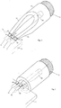
- FIG. 1 shows an enlarged perspective view a measuring tip unit E according to the invention consisting of a flat with the cover removed Metal housing 1 and one formed on one end face Coaxial line connection 2 in the form of a coaxial connector, on which a measuring device, not shown, for example a network analyzer, leading coaxial cable is screwable.
- a Microwave substrate 3 attached, on which a coplanar line 4 is formed, which is different from one Coaxial line connection 2 facing end of the Housing extends to the opposite end.
- this is a coplanar line trained as a three-band line and consists of a central strip line 5 and through slots thereof separate side ground strip conductors 6 and 7.
- the Coaxial line connection 2 merges into three side by side arranged terminal lugs 8, 9, 10, the middle Terminal lug 8 is with the inner conductor and the side Terminal lugs 9 and 10 are connected to the outer conductor of the Coaxial line connection 2 connected.
- These connecting flags 8, 9, 10 protrude through an opening in the front wall of the housing 1 inside and lie flat with pressure the surface of the stripline 5, 6 and 7 of the coplanar line on. If the contact by pressure is not is sufficient, the connection lugs with the strip conductors also electrically by soldering or bond wires be connected.
- the housing 1 In the end face opposite the coaxial connector 2 the housing 1 is formed an opening 11 through which three spaced thin next to each other Protruding needles 12 from the inside of the housing. in the These needles 12 with the three strip conductors are the housing 5, 6, 7 of the coplanar line. Details of this The needle arrangement shows the enlarged sectional view Fig. 2.
- the needles 12 are side by side in one body 13 made of insulating material, which has a retaining ring 14 is releasably attached in the opening 11 of the housing.
- the needles have a rectangular or round cross-section and are slightly conical, their thinner exterior End 16 and their thicker inner end is respectively chiselled.
- the needles 12 are also with their ends 16 converging in the body 13 used so that the tips 16 for contacting with the microwave circuit M to be measured possess a small distance of only a few um while the ends lying in the housing through the stripline 5, 6, 7 of the coplanar line have a predetermined distance.
- the mutual conical distance between the needles 12 and her conical diameter is taking into account the Dielectric constant of the insulating body 13 selected so that between the tips 16 of the needles 12 one for the There is predetermined impedance in each application.
- the chisel-shaped bevel of the tips 16 is also chosen so that at a slope shown in Fig. 2 Put on the measuring tip unit E the needle ends Surface contact with the areas to be contacted Establish microwave circuit M.
- the diameter of the needles at the thicker end lies, for example, between 0.5 and 1 mm and on the outside pointed end between 50 to 100 ⁇ m.
- the probe unit E has an input impedance of 50 ⁇ and is therefore for measurements in 50 ⁇ systems suitable.
- a measuring tip unit E according to FIG. 1 can, however also easily to other input impedances be converted between the measuring tips. It is for that only required in the coplanar line 5, 6, 7 for example in the middle of a corresponding impedance transformation circuit to install and the distances of the Needles 12 according to this desired impedance choose. In this way, for example, between the Probe tips have an input impedance in the range of a few ⁇ to a few k ⁇ can be selected while connecting to the measuring device continues via a 50 ⁇ coaxial cable.
- a coplanar line could also consist of only two strip conductors existing symmetrical or asymmetrical Coplanar line can be provided in the housing, in this case, only two needles 12 are also provided a symmetrical or asymmetrical two-point measurement signal recording enable.
- the housing 1 of the probe unit E can optionally other passive and / or active circuits installed are required for the operation of the measuring tip unit will.
- the substrate 3 Circuits for direct voltage supply via the measuring tips be provided to the test object, which is on the side cables led out on the housing with external arranged Devices are connected.
- FIG. 3 Another possibility, as with an inventive Probe unit E directly circuit parts of a vectorial network analyzer in the probe assembly can be integrated, Fig. 3.
- the Measurement setup for measuring a measurement object 21, for example a voltage amplifier for high frequencies, by means of of a vector network analyzer 22 is shown.
- measuring points m1 integrated up to m4 of the network analyzer.
- These measuring points consist, for example, of frequency-converting components such as mixers, amplifiers, analog / digital converters and the like active and passive components that thus via the coplanar line as close as possible to the measurement object are switched on, which is particularly important for measurements in Maximum frequency range is an advantage.
- additional other assemblies such as generators, noise sources or the like, which are then integrated in the immediate vicinity of the object to be measured with the coplanar line are connected and, if necessary, from the Housing leads leading to the outside with other devices are connected.
- FIG. 3 also shows how by Impedance transformation circuits in the form of resistor networks 23 and 24 in the probe units E1 and E2 are integrated, the most appropriate Input impedances between the probe tips 12 can be selected with which the corresponding inputs and Output connections of the measurement object 21 can be contacted.
- the distance is Contact tips of the probe unit E1 and the impedance transformation circuit 23 dimensioned so that between the needles 12 have an input impedance of less than 100 ⁇ prevails, even though the probe unit E1 has a 50 ⁇ coaxial cable connected to the network analyzer 22 is.
- the probe tips of unit E2 are therefore arranged at a correspondingly greater distance from each other and the impedance transformation network 24 dimensioned so that an input impedance of, for example 10 k ⁇ exists.
- FIG. 4 and 5 show embodiments according to the invention for the transition from a coaxial line connection 2 to a coplanar line.
- Fig. 4 shows the transition to a symmetrical three-strip line coplanar line
- Fig. 5 shows the transition to an asymmetrical two-strip line coplanar line.
- the outer conductor 30 of the coaxial line connection 2 split and runs out in two opposite, gradually tapering triangular Sections 31, 32, the ends 35, 36 also light are turned towards each other.
- the inner conductor 34 is tapered. This shape of the exterior and Inner conductor is achieved that on the coaxial side Gradually end radially symmetrical electromagnetic field passes into the field distribution of a coplanar line, that between the tapered ends 35, 36 of the opposite Outer conductor sections 31, 32 and that in one Flat tapered end 37 of the inner conductor is formed.
- the ends 35, 36, 37 are via connecting lugs 8, 9, 10 directly with those on the substrate 3 trained strip conductors 5, 6, 7 of the coplanar line 4 connected.
Landscapes
- Physics & Mathematics (AREA)
- General Physics & Mathematics (AREA)
- Measuring Leads Or Probes (AREA)
- Testing Or Measuring Of Semiconductors Or The Like (AREA)
Applications Claiming Priority (2)
| Application Number | Priority Date | Filing Date | Title |
|---|---|---|---|
| DE19641880 | 1996-10-10 | ||
| DE19641880A DE19641880A1 (de) | 1996-10-10 | 1996-10-10 | Meßspitzeneinheit zum Kontaktieren von planaren Mikrowellenschaltungen |
Publications (3)
| Publication Number | Publication Date |
|---|---|
| EP0836097A2 true EP0836097A2 (fr) | 1998-04-15 |
| EP0836097A3 EP0836097A3 (fr) | 1999-05-12 |
| EP0836097B1 EP0836097B1 (fr) | 2005-07-20 |
Family
ID=7808415
Family Applications (1)
| Application Number | Title | Priority Date | Filing Date |
|---|---|---|---|
| EP97117312A Expired - Lifetime EP0836097B1 (fr) | 1996-10-10 | 1997-10-07 | Sonde de mesure |
Country Status (3)
| Country | Link |
|---|---|
| US (1) | US6078184A (fr) |
| EP (1) | EP0836097B1 (fr) |
| DE (2) | DE19641880A1 (fr) |
Cited By (1)
| Publication number | Priority date | Publication date | Assignee | Title |
|---|---|---|---|---|
| WO2010041188A1 (fr) * | 2008-10-08 | 2010-04-15 | Nxp B.V. | Sonde pour tranche |
Families Citing this family (15)
| Publication number | Priority date | Publication date | Assignee | Title |
|---|---|---|---|---|
| DE19832021C2 (de) * | 1998-07-16 | 2000-05-11 | Bosch Gmbh Robert | Tastkopf |
| DE19945176B4 (de) * | 1999-09-21 | 2005-07-28 | Rosenberger Hochfrequenztechnik Gmbh & Co. | Anordnung von Federkontakten in einem vorbestimmten Raster |
| DE19945178C2 (de) * | 1999-09-21 | 2003-05-28 | Rosenberger Hochfrequenztech | Meßspitze zur Hochfrequenzmessung und Verfahren zu deren Herstellung |
| US6366104B2 (en) * | 2000-02-15 | 2002-04-02 | Hughes Electronics Corp. | Microwave probe for surface mount and hybrid assemblies |
| US6597185B1 (en) * | 2000-09-20 | 2003-07-22 | Neocera, Inc. | Apparatus for localized measurements of complex permittivity of a material |
| DE20021685U1 (de) | 2000-12-21 | 2001-03-15 | Rosenberger Hochfrequenztechnik GmbH & Co, 83413 Fridolfing | Hochfrequenz-Tastspitze |
| RU2293339C1 (ru) * | 2005-07-25 | 2007-02-10 | Федеральное государственное унитарное предприятие "Научно-производственное предприятие "Исток" (ФГУП НПП "Исток") | Многоконтактный зонд для испытания планарных элементов интегральных схем |
| DE102006021569A1 (de) | 2006-02-09 | 2007-08-16 | Rohde & Schwarz Gmbh & Co. Kg | Prüfsystem für einen Schaltungsträger |
| US8903675B2 (en) * | 2011-10-14 | 2014-12-02 | Vibrant Corporation | Acoustic systems and methods for nondestructive testing of a part through frequency sweeps |
| CN114514428A (zh) | 2019-10-09 | 2022-05-17 | 联邦计量指标研究所 | 同轴晶圆探针及对应的制造方法 |
| US12092657B2 (en) * | 2020-02-26 | 2024-09-17 | Raytheon Company | Test probe adapter |
| JP7230089B2 (ja) * | 2021-03-26 | 2023-02-28 | アンリツ株式会社 | コプレーナ線路とコネクタとの接続構造及び接続方法、並びにそれを用いたサンプリングオシロスコープ |
| JP7680696B2 (ja) * | 2022-01-06 | 2025-05-21 | 日本電信電話株式会社 | 誘電分光センサ |
| FR3162523A1 (fr) | 2024-05-21 | 2025-11-28 | Institut Federal De Metrologie Metas | Sonde de mesure pour le test de dispositifs semi-conducteurs sur une plaquette, et son procédé de fabrication |
| WO2025233253A1 (fr) | 2024-05-04 | 2025-11-13 | Institut Federal De Metrologie Metas | Sonde de mesure pour test sur tranche de dispositifs à semi-conducteur, et son procédé de fabrication |
Family Cites Families (16)
| Publication number | Priority date | Publication date | Assignee | Title |
|---|---|---|---|---|
| DE1516121A1 (de) * | 1966-02-23 | 1969-09-25 | Eugen Lehmann Elektronische Me | Tastkopf fuer elektrische Messgeraete |
| DE1591413B2 (de) * | 1967-08-23 | 1970-04-02 | Rohde & Schwarz, 8OOO München | Anordnung zum übergang von einer Koaxialleitung auf mindestens zwei in einer Ebene quer zur Koaxialleitungsachse nach verschiedenen Richtungen verlaufende symmetrische Bandleitungen |
| US3622915A (en) * | 1970-03-16 | 1971-11-23 | Meca Electronics Inc | Electrical coupler |
| DD153439A1 (de) * | 1980-10-09 | 1982-01-06 | Wolfram Senf | Anordnung zur messung von impedanzen an hoechstfrequenzflachstrukturen |
| US4593243A (en) * | 1984-08-29 | 1986-06-03 | Magnavox Government And Industrial Electronics Company | Coplanar and stripline probe card apparatus |
| DE3530925C2 (de) * | 1985-08-29 | 1994-04-14 | Siemens Ag | Prüfvorrichtung für koaxiale HF-Verbinder |
| US4783625A (en) * | 1986-08-21 | 1988-11-08 | Tektronix, Inc. | Wideband high impedance card mountable probe |
| US4894612A (en) * | 1987-08-13 | 1990-01-16 | Hypres, Incorporated | Soft probe for providing high speed on-wafer connections to a circuit |
| US4871964A (en) * | 1988-04-12 | 1989-10-03 | G. G. B. Industries, Inc. | Integrated circuit probing apparatus |
| US4849689A (en) * | 1988-11-04 | 1989-07-18 | Cascade Microtech, Inc. | Microwave wafer probe having replaceable probe tip |
| US5045781A (en) * | 1989-06-08 | 1991-09-03 | Cascade Microtech, Inc. | High-frequency active probe having replaceable contact needles |
| GB9100815D0 (en) * | 1991-01-15 | 1991-02-27 | British Telecomm | Coplanar waveguide ribbon |
| US5221895A (en) * | 1991-12-23 | 1993-06-22 | Tektronix, Inc. | Probe with microstrip transmission lines |
| US5488313A (en) * | 1993-07-16 | 1996-01-30 | Litton Systems, Inc. | Test probe and circuit board arrangement for the circuit under test for microstrip circuitry |
| US5506515A (en) * | 1994-07-20 | 1996-04-09 | Cascade Microtech, Inc. | High-frequency probe tip assembly |
| US5565788A (en) * | 1994-07-20 | 1996-10-15 | Cascade Microtech, Inc. | Coaxial wafer probe with tip shielding |
-
1996
- 1996-10-10 DE DE19641880A patent/DE19641880A1/de not_active Withdrawn
-
1997
- 1997-10-07 DE DE59712366T patent/DE59712366D1/de not_active Expired - Lifetime
- 1997-10-07 EP EP97117312A patent/EP0836097B1/fr not_active Expired - Lifetime
- 1997-10-10 US US08/948,805 patent/US6078184A/en not_active Expired - Lifetime
Cited By (1)
| Publication number | Priority date | Publication date | Assignee | Title |
|---|---|---|---|---|
| WO2010041188A1 (fr) * | 2008-10-08 | 2010-04-15 | Nxp B.V. | Sonde pour tranche |
Also Published As
| Publication number | Publication date |
|---|---|
| EP0836097B1 (fr) | 2005-07-20 |
| DE19641880A1 (de) | 1998-04-16 |
| US6078184A (en) | 2000-06-20 |
| EP0836097A3 (fr) | 1999-05-12 |
| DE59712366D1 (de) | 2005-08-25 |
Similar Documents
| Publication | Publication Date | Title |
|---|---|---|
| EP0836097B1 (fr) | Sonde de mesure | |
| DE19614506B4 (de) | Aufbau und Verfahren zur Auswertung von Signalzuständen in einem Sondenmeßnetzwerk | |
| DE60314824T2 (de) | Prüfkopf für RF-Gerät, und im Prüfkopf eingebaute Prüfnadel | |
| DE3716240A1 (de) | Pruefadapter, insbesondere fuer eine integrierte schaltung | |
| DE60300223T2 (de) | System und Verfahren zur Verbindung von Hochfrequenzübertragungsleitungen | |
| EP0915342B1 (fr) | Tête de sonde pour microstructures avec interface | |
| DE10143173A1 (de) | Wafersonde | |
| DE2608430B2 (de) | Halterung für programmierbare Sonden zum Anschluß an ein in einer elektrischen Prüfung befindliches Bauteil | |
| DE102005053146A1 (de) | Messspitze zur Hochfrequenzmessung | |
| DE102007013312A1 (de) | Sondensystem mit hoher Bandbreite | |
| DE3535926A1 (de) | Mikroschaltungs-taster mit angepasster impedanz | |
| DE19945176B4 (de) | Anordnung von Federkontakten in einem vorbestimmten Raster | |
| DE68909510T2 (de) | Steckverbindung für eine Mikrowelleneinheit. | |
| DE19540614C2 (de) | Bauteil zum elektrischen Verbinden einer planaren Struktur mit einer Koaxialstruktur | |
| DE102009008156B4 (de) | Elektrische Hochfrequenz-Prüfstiftvorrichtung und Verwendung einer solchen | |
| DE102004044975A1 (de) | Koaxiales Verbindungsteil | |
| DE19602156C1 (de) | Anschlußstecker zum Anschließen von Adern eines Kabels an ein elektrisches Gerät | |
| DE3620111C2 (de) | Hochfrequenz-Koaxialbuchse | |
| DE3611865C2 (fr) | ||
| DD153439A1 (de) | Anordnung zur messung von impedanzen an hoechstfrequenzflachstrukturen | |
| DE19847244A1 (de) | Prüfkopf für Mikrostrukturen mit Schnittstelle | |
| DE10117914B4 (de) | Hochfrequenzschalter für Mikrostreifenleitungsstrukturen | |
| EP1476938B1 (fr) | Dispositif pour generer des ondes dans la zone de haute frequence | |
| DE3009236C2 (de) | Anordnung mit Kontaktbuchsen für elektrische Anschlüsse | |
| DE19736564B4 (de) | Kontaktvorrichtung |
Legal Events
| Date | Code | Title | Description |
|---|---|---|---|
| PUAI | Public reference made under article 153(3) epc to a published international application that has entered the european phase |
Free format text: ORIGINAL CODE: 0009012 |
|
| AK | Designated contracting states |
Kind code of ref document: A2 Designated state(s): DE FR GB |
|
| PUAL | Search report despatched |
Free format text: ORIGINAL CODE: 0009013 |
|
| AK | Designated contracting states |
Kind code of ref document: A3 Designated state(s): AT BE CH DE DK ES FI FR GB GR IE IT LI LU MC NL PT SE |
|
| 17P | Request for examination filed |
Effective date: 19990426 |
|
| AKX | Designation fees paid |
Free format text: DE FR GB |
|
| 17Q | First examination report despatched |
Effective date: 20041119 |
|
| GRAP | Despatch of communication of intention to grant a patent |
Free format text: ORIGINAL CODE: EPIDOSNIGR1 |
|
| GRAS | Grant fee paid |
Free format text: ORIGINAL CODE: EPIDOSNIGR3 |
|
| GRAA | (expected) grant |
Free format text: ORIGINAL CODE: 0009210 |
|
| AK | Designated contracting states |
Kind code of ref document: B1 Designated state(s): DE FR GB |
|
| REG | Reference to a national code |
Ref country code: GB Ref legal event code: FG4D Free format text: NOT ENGLISH |
|
| GBT | Gb: translation of ep patent filed (gb section 77(6)(a)/1977) |
Effective date: 20050720 |
|
| REF | Corresponds to: |
Ref document number: 59712366 Country of ref document: DE Date of ref document: 20050825 Kind code of ref document: P |
|
| ET | Fr: translation filed | ||
| PLBE | No opposition filed within time limit |
Free format text: ORIGINAL CODE: 0009261 |
|
| STAA | Information on the status of an ep patent application or granted ep patent |
Free format text: STATUS: NO OPPOSITION FILED WITHIN TIME LIMIT |
|
| 26N | No opposition filed |
Effective date: 20060421 |
|
| REG | Reference to a national code |
Ref country code: FR Ref legal event code: PLFP Year of fee payment: 19 |
|
| REG | Reference to a national code |
Ref country code: FR Ref legal event code: PLFP Year of fee payment: 20 |
|
| PGFP | Annual fee paid to national office [announced via postgrant information from national office to epo] |
Ref country code: DE Payment date: 20161028 Year of fee payment: 20 Ref country code: FR Payment date: 20161025 Year of fee payment: 20 Ref country code: GB Payment date: 20161025 Year of fee payment: 20 |
|
| REG | Reference to a national code |
Ref country code: DE Ref legal event code: R071 Ref document number: 59712366 Country of ref document: DE |
|
| REG | Reference to a national code |
Ref country code: GB Ref legal event code: PE20 Expiry date: 20171006 |
|
| PG25 | Lapsed in a contracting state [announced via postgrant information from national office to epo] |
Ref country code: GB Free format text: LAPSE BECAUSE OF EXPIRATION OF PROTECTION Effective date: 20171006 |