EP0836101A2 - Capteur de contrÔle optique pour machines d'emballage - Google Patents
Capteur de contrÔle optique pour machines d'emballage Download PDFInfo
- Publication number
- EP0836101A2 EP0836101A2 EP97117302A EP97117302A EP0836101A2 EP 0836101 A2 EP0836101 A2 EP 0836101A2 EP 97117302 A EP97117302 A EP 97117302A EP 97117302 A EP97117302 A EP 97117302A EP 0836101 A2 EP0836101 A2 EP 0836101A2
- Authority
- EP
- European Patent Office
- Prior art keywords
- air
- housing
- monitoring device
- monitoring
- transmitter
- Prior art date
- Legal status (The legal status is an assumption and is not a legal conclusion. Google has not performed a legal analysis and makes no representation as to the accuracy of the status listed.)
- Granted
Links
- 238000004806 packaging method and process Methods 0.000 title claims abstract description 8
- 230000003287 optical effect Effects 0.000 title claims abstract description 5
- 238000012806 monitoring device Methods 0.000 claims abstract description 19
- 239000000428 dust Substances 0.000 claims abstract description 6
- 238000012544 monitoring process Methods 0.000 claims description 25
- 239000000463 material Substances 0.000 claims description 10
- 230000005693 optoelectronics Effects 0.000 claims description 5
- 238000011109 contamination Methods 0.000 claims description 3
- 239000005022 packaging material Substances 0.000 claims description 3
- 239000003365 glass fiber Substances 0.000 claims description 2
- 210000000056 organ Anatomy 0.000 description 6
- 238000004140 cleaning Methods 0.000 description 5
- 239000002245 particle Substances 0.000 description 4
- 239000000835 fiber Substances 0.000 description 3
- 238000012536 packaging technology Methods 0.000 description 3
- 230000004888 barrier function Effects 0.000 description 2
- 230000001419 dependent effect Effects 0.000 description 1
- 230000008021 deposition Effects 0.000 description 1
- 239000002184 metal Substances 0.000 description 1
- 238000000034 method Methods 0.000 description 1
- 239000012780 transparent material Substances 0.000 description 1
Images

Classifications
-
- G—PHYSICS
- G01—MEASURING; TESTING
- G01V—GEOPHYSICS; GRAVITATIONAL MEASUREMENTS; DETECTING MASSES OR OBJECTS; TAGS
- G01V8/00—Prospecting or detecting by optical means
- G01V8/10—Detecting, e.g. by using light barriers
- G01V8/12—Detecting, e.g. by using light barriers using one transmitter and one receiver
Definitions
- the invention relates to a monitoring device with emitted and received test beam, in particular an optoelectronic Monitoring device with light beam for material webs and / or Blanks from packaging material in connection with packaging machines, wherein the monitoring body at least one (Optical) transmitter and preferably one opposite Has receiver.
- monitoring bodies In packaging technology, there are monitoring bodies in many areas with a test beam, especially a light barrier, required. These monitoring bodies have at the task, the work processes of the (packaging) machine to control, for example via print marks on material webs or cuts. On the other hand, there is also the exact position Arrangement and / or design of material webs and monitor blanks.
- the operation of the (packaging) machine is correct Functioning of the monitoring bodies dependent. This in turn are sensitive to contamination, especially compared to the inevitable dust and Particle deposits.
- the invention has for its object monitoring organs of the type described to improve that they have a have increased functional reliability.
- the monitoring device is used to achieve this object characterized in that in the range of transmitters and / or the receiver preferably constantly in the direction of Transmitter and / or receiver leading gas or air jet generated becomes.
- permanent functionality is accordingly of the supervisory bodies ensures that their individual organs are kept free of dust and other deposits.
- a gas or air flow is generated, which is one of causes organs to flow away, so that deposition of dust and other particles is not possible.
- the parts the monitoring body in particular the transmitter and / or receiver, be arranged in a housing or in partial housings for the exit of the test beam is an opening or one for the Have a test beam permeable wall or a window.
- the gas or air flow directed so that the for the test beam permeable wall or the window of the housing from Deposits are kept free. Air can in particular introduced into the housing under overpressure and by targeted positioned exit bores from the housing in the area emerge from the permeable wall.
- Another special feature of the invention is the handling a light-guiding organ, in particular a light-guiding cable.
- a light-guiding organ in particular a light-guiding cable.
- This is according to the invention in a tube, hose or Housing arranged, which one opposite the fiber optic cable guaranteed annular space. Through this one Gas or air flow towards the end face of the light guide cable passed through.
- the light guide cable with one Head and possibly an angular optics equipped.
- the end of the fiber optic cable is supported in a housing. The air flow emerges from the free side Pipe or hose or out of the housing, i.e. in the direction away from the end of the fiber optic cable.
- 1 to 3 is an exemplary embodiment of an optoelectronic Monitoring element 10 a so-called fork light barrier shown. This is mainly used in packaging technology used, for example for position control and -control of material webs from packaging material etc.
- the monitoring member 10 is with a transmitter 11 and Receiver 12 equipped. Preferably serves as transmitter 11 a light emitting diode. A photocell serves as the receiver 12. From A light beam is directed onto the receiver 12 at the transmitter 11. The one to be monitored is between transmitter 11 and receiver 12 Passed object, for example the material web.
- Transmitter 11 and receiver 12 are housed in a housing 13. Overall, the housing has a U-shaped shape. In one leg of the housing 13, namely in a partial housing 14, the transmitter is 11. In another, at a distance arranged sub-housing 15, the receiver 12 is housed. This sits on a circuit board 16 with electrical components. The sub-housings 14, 15 are attached to a support plate 17. This also serves to attach the transmitter 11 and the Receiver 12, the latter on the board 16. One between the Part housing 14, 15 bore 18 is used for attachment of the monitoring organ on a carrier of the (packaging) machine.
- the sub-housings 14, 15 consist of translucent or transparent material, especially plastic.
- the housing 13 can be designed so that at least one another facing walls 19, 20 of the housing 13 made of translucent Material consist of a beam of light from the transmitter 11 to pass through to the receiver 12.
- a gas flow in particular an air flow to targeted areas continuously or intermittently of the monitoring body 10 directed.
- the airflow will guided so that the area between transmitter 11 and receiver 12 kept clear, any particles etc. are blown away.
- Of the Air flow is therefore directed so that an air flow in Direction away from the optoelectronic organs.
- the area between the sub-housings 14, 15, i.e. a control room 37, are kept clear.
- the airflow is directed so that a flow to the free sides this control room 37 is directed.
- the air flow or the clearance air is shown in the Embodiment via an air line 21, the hose can be formed, passed into the housing 13.
- the air line 21 passes through an opening provided with a seal 22 23 into the sub-housing 15 via the support plate 17.
- the cleaning air passes through radially directed outlet bores 24 in the partial housing 15. This is in the lateral areas (not shown) connected to the sub-housing 14, so that from the partial housing 15 cleaning air, that is air under pressure, also gets into the partial housing 14.
- the housing 13 or the partial housing 14, 15 are with air holes 25, 26 provided, through which the cleaning air from the housing 13 or the partial housings 14 and 15 flows out, namely specifically in the area between the opposing ones Walls 19, 20, so in the control room, and out of this out again.
- This pressurized air causes Keep the surfaces of the walls 19, 20 free.
- the air holes 25, 26 act like air nozzles due to their size.
- the air holes 25, 26 are positioned according to the cleaning purpose.
- a number of air holes 25, namely three each, is located in the area of a throat of wall 19 or 20 on the one hand and a transverse connecting wall 27 between the walls 19 and 20. These air holes 25 are diagonally and thus to the opposite Wall 19, 20. Further air holes 26 are in the area the connecting wall 27, on both sides of the bore 18. This creates a constant flow of air from the interior of the monitoring body, i.e. out of the control room 37, causes.
- Air line 21 and cable 28 form a unit.
- the cable 28 is within the Air line 21 arranged.
- the air line 21 is dimensioned so that a free, annular cross section for the air flow remains with the cable 28.
- the cable 28 occurs at the free End from the air line 21, in the housing 13th or partial housing 15.
- the cable 28 is in this end region a seal 29 sealed against the air line 21.
- the monitoring body 10 an amplifier 30 is assigned. This unity is positioned at a distance from the monitoring device on the machine. The distance can be, for example, 50 cm.
- the amplifier 30 consists of an amplifier housing 31. Inside an electrical control unit 32 is arranged thereon. The cable 28 leads to this from the monitoring device 10.
- the control unit 32 is in the supply in the present case of the monitoring body 10 with (cleaning) air included.
- An electric line 33 and leads to the control unit 32 a separate air line 34. This is to a compressed air source (not shown) connected to the system with (oil-free) Compressed air supplied.
- An air duct 35 is formed within the amplifier 30 outside the range of the control unit 32 from the mouth of the Air line 34 leads to a common connection 36. This is on one opposite the inlet side of air line 34 and electric line 33 formed transverse sidewall.
- connection 36 which is designed as a connection piece, is guided by the air duct 35.
- the cable 28 leads from the control unit 32 into the connection 36 and thus in the end of the air line 21. This is in the connection 36 anchored.
- the air duct 35 is inside the amplifier housing 31 in an investment material made of plastic or the like educated.
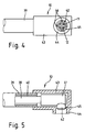
- a light guide 38 for example made of glass fibers, is guided in an outer tube 39. It can be alternatively also act as a hose.
- the inside diameter this outer tube 39 is significantly larger than the outer dimension the light guide 38. This creates an annular channel 40, in which a gas or air flow is generated for (free) end of the light pipe 38 directed.
- the light guide ends in a head 41, preferably made of metal.
- the head 41 is arranged in a (cylindrical) housing 43. This is connected to the free end of the outer tube 39 and has 41 larger internal dimensions according to the dimensions of the head, so that a space for the passage of the gas or Air flow is formed. On the side of the housing is an outside open outlet nozzle 44 attached.
- the light pipe 38 or the head 41 is in the region of an outlet opening of the housing 43 stored.
- the angled optics 42 are seated in an outlet port 44 lateral opening 45.
- the end of the The light conduit 38 flows through the opening 45 through, namely through free segments in the area between angular optics 42, outlet connection 44 and the supporting ribs 46.
- Light pipe 38 constructed so that it transmitter 11 and receiver 12 has side by side.
Landscapes
- Physics & Mathematics (AREA)
- Life Sciences & Earth Sciences (AREA)
- General Life Sciences & Earth Sciences (AREA)
- General Physics & Mathematics (AREA)
- Geophysics (AREA)
- Investigating Materials By The Use Of Optical Means Adapted For Particular Applications (AREA)
- Containers And Plastic Fillers For Packaging (AREA)
- Optical Measuring Cells (AREA)
- Length Measuring Devices By Optical Means (AREA)
Applications Claiming Priority (2)
| Application Number | Priority Date | Filing Date | Title |
|---|---|---|---|
| DE19641988A DE19641988A1 (de) | 1996-10-11 | 1996-10-11 | Verpackungsmaschine mit optischen Überwachungsorganen |
| DE19641988 | 1996-10-11 |
Publications (3)
| Publication Number | Publication Date |
|---|---|
| EP0836101A2 true EP0836101A2 (fr) | 1998-04-15 |
| EP0836101A3 EP0836101A3 (fr) | 2000-05-31 |
| EP0836101B1 EP0836101B1 (fr) | 2002-02-13 |
Family
ID=7808491
Family Applications (1)
| Application Number | Title | Priority Date | Filing Date |
|---|---|---|---|
| EP97117302A Expired - Lifetime EP0836101B1 (fr) | 1996-10-11 | 1997-10-07 | Capteur de contrôle optique pour machines d'emballage |
Country Status (3)
| Country | Link |
|---|---|
| US (1) | US6150946A (fr) |
| EP (1) | EP0836101B1 (fr) |
| DE (2) | DE19641988A1 (fr) |
Cited By (2)
| Publication number | Priority date | Publication date | Assignee | Title |
|---|---|---|---|---|
| US6282969B1 (en) * | 1998-09-30 | 2001-09-04 | Veleo Electrical Systems, Inc. | Optically clear housing and reduced cure time potting compound for use with object sensor |
| CN100565240C (zh) * | 2004-08-02 | 2009-12-02 | 株式会社电装 | 超声传感器组件 |
Families Citing this family (4)
| Publication number | Priority date | Publication date | Assignee | Title |
|---|---|---|---|---|
| DE19920403B4 (de) * | 1998-10-08 | 2008-02-14 | Endress + Hauser Gmbh + Co. Kg | Optoelektronischer Koppler |
| DE19928360A1 (de) * | 1999-06-21 | 2001-03-29 | Focke & Co | Verfahren und Vorrichtung zum Herstellen und/oder Verpacken von Zigaretten |
| DE10015511B4 (de) * | 2000-03-30 | 2006-10-19 | Ifm Electronic Gmbh | Optoelektronische Sensorvorrichtung |
| WO2011016908A1 (fr) * | 2009-08-03 | 2011-02-10 | Illinois Tool Works Inc. | Capteur dinterruption optique doté de diodes électroluminescentes opposées |
Citations (5)
| Publication number | Priority date | Publication date | Assignee | Title |
|---|---|---|---|---|
| DE3008309A1 (de) | 1980-03-04 | 1981-09-10 | Siemens AG, 1000 Berlin und 8000 München | Lichtschranke zur erfassung mechanischer bewegungen |
| EP0146800A1 (fr) | 1983-12-06 | 1985-07-03 | SASIB S.p.A. | Dispositif de contrôle pour des groupes de cigarettes |
| US4627319A (en) | 1984-02-23 | 1986-12-09 | G.D. Societa Per Azioni | Device for supplying webs of wrapping material to a cigarette making machine of the two rod type |
| US5260583A (en) | 1991-02-11 | 1993-11-09 | Rye Timothy W | Method and apparatus for detecting edge cracks |
| DE9421170U1 (de) | 1994-04-28 | 1995-07-27 | Siemens Nixdorf Informationssysteme AG, 33106 Paderborn | Selbstreinigende optoelektronische Abtasteinrichtung |
Family Cites Families (13)
| Publication number | Priority date | Publication date | Assignee | Title |
|---|---|---|---|---|
| US3091114A (en) * | 1959-12-17 | 1963-05-28 | Air Reduction | Method and apparatus for testing sealed packages for leaks |
| CA973086A (en) * | 1971-02-12 | 1975-08-19 | Goffredo Gianese | Apparatus for feeding and cutting web material |
| US4348334A (en) * | 1979-02-02 | 1982-09-07 | Ciba-Geigy Ag | Process for producing the magnesium salt of 3-nitro-naphthalene-1,5-disulfonic acid (nitro-Armstrong's acid) |
| DE3812689A1 (de) * | 1988-04-16 | 1989-11-02 | Focke & Co | Vorrichtung zum pruefen von zigaretten |
| IT1220371B (it) * | 1988-05-20 | 1990-06-15 | P M System Srl | Metodo per controllare la tenuta della saldatura delle fialette monodose di materiale termoplastico ottenute collegate affiancate in unita' multiple ed apparecchiatura per l'attuazione di detto metodo |
| US5138178A (en) * | 1990-12-17 | 1992-08-11 | Xerox Corporation | Photoelectric paper basis weight sensor |
| DE4100239A1 (de) * | 1991-01-07 | 1992-07-09 | Focke & Co | Faltvorrichtung zum herstellen von (zigaretten-)packungen |
| DE4200971C2 (de) * | 1992-01-16 | 1997-08-07 | Krieg Gunther | Verfahren und Vorrichtung für die Schadstoffdetektion und - identifikation in Getränkeflaschen in Abfüllinien |
| DE4302777A1 (de) * | 1993-02-02 | 1994-08-04 | Focke & Co | Vorrichtung zum Prüfen von Zigaretten |
| JPH07115212A (ja) * | 1993-10-19 | 1995-05-02 | Toshiba Corp | 光半導体装置 |
| DE29601159U1 (de) * | 1996-01-24 | 1996-05-02 | Färber, Adolf, 57399 Kirchhundem | Vorrichtung zur berührungslosen Überwachung der Durchsatzmenge eines strömenden Materials |
| US5714763A (en) * | 1996-03-25 | 1998-02-03 | Measurex Corporation | Method and apparatus for optical alignment of a measuring head in an X-Y plane |
| US5798531A (en) * | 1996-06-10 | 1998-08-25 | Harris Instrument Corporation | System for detecting small holes in moving articles |
-
1996
- 1996-10-11 DE DE19641988A patent/DE19641988A1/de not_active Withdrawn
-
1997
- 1997-10-07 DE DE59706367T patent/DE59706367D1/de not_active Expired - Fee Related
- 1997-10-07 EP EP97117302A patent/EP0836101B1/fr not_active Expired - Lifetime
- 1997-10-08 US US08/947,272 patent/US6150946A/en not_active Expired - Fee Related
Patent Citations (5)
| Publication number | Priority date | Publication date | Assignee | Title |
|---|---|---|---|---|
| DE3008309A1 (de) | 1980-03-04 | 1981-09-10 | Siemens AG, 1000 Berlin und 8000 München | Lichtschranke zur erfassung mechanischer bewegungen |
| EP0146800A1 (fr) | 1983-12-06 | 1985-07-03 | SASIB S.p.A. | Dispositif de contrôle pour des groupes de cigarettes |
| US4627319A (en) | 1984-02-23 | 1986-12-09 | G.D. Societa Per Azioni | Device for supplying webs of wrapping material to a cigarette making machine of the two rod type |
| US5260583A (en) | 1991-02-11 | 1993-11-09 | Rye Timothy W | Method and apparatus for detecting edge cracks |
| DE9421170U1 (de) | 1994-04-28 | 1995-07-27 | Siemens Nixdorf Informationssysteme AG, 33106 Paderborn | Selbstreinigende optoelektronische Abtasteinrichtung |
Cited By (2)
| Publication number | Priority date | Publication date | Assignee | Title |
|---|---|---|---|---|
| US6282969B1 (en) * | 1998-09-30 | 2001-09-04 | Veleo Electrical Systems, Inc. | Optically clear housing and reduced cure time potting compound for use with object sensor |
| CN100565240C (zh) * | 2004-08-02 | 2009-12-02 | 株式会社电装 | 超声传感器组件 |
Also Published As
| Publication number | Publication date |
|---|---|
| DE59706367D1 (de) | 2002-03-21 |
| US6150946A (en) | 2000-11-21 |
| DE19641988A1 (de) | 1998-04-16 |
| EP0836101A3 (fr) | 2000-05-31 |
| EP0836101B1 (fr) | 2002-02-13 |
Similar Documents
| Publication | Publication Date | Title |
|---|---|---|
| EP2419709B1 (fr) | Dispositif pour déterminer la teneur en eau d'un objet sous test | |
| DE102007005049A1 (de) | Vorrichtung in der Spinnereivorbereitung zum Abscheiden von Fremdstoffen an einer Fördereinrichtung für Fasermaterial, z.B. Baumwolle, Chemiefasern o. dgl. | |
| EP0836101B1 (fr) | Capteur de contrôle optique pour machines d'emballage | |
| SE8901704D0 (sv) | Hylsa foer att haalla fast en i slangfilter ingaaende filterslang | |
| DE102014009690A1 (de) | Vorrichtung in der Spinnereivorbereitung, Ginnerei o. dgl. zum Erkennen und Ausscheiden von Fremdstoffen in oder zwischen Fasermaterial, insbesondere Baumwolle | |
| EP0909577A2 (fr) | Appareil mobile pour l'epuration de l'air pollué | |
| DE19704718A1 (de) | Verfahren und Vorrichtung zum optoelektronischen Überwachen von Verpackungsmaterial | |
| EP0059473A1 (fr) | Dispositif de nettoyage mobile pour trains d'étirage de machines à filer et à retordre | |
| DE102019110637A1 (de) | Vorrichtung, System und Verfahren zur Erzeugung eines Gasstroms zum Schutz mindestens eines optischen Elements | |
| EP0084087B1 (fr) | Dispositif d'aspiration de fil | |
| EP0931865A1 (fr) | Dispositif de tension et de détection de la trame pour métiers à tisser à tuyères, en particulier avec insertion pneumatique de la trame | |
| DE10255747A1 (de) | Laseranordnung zur Bearbeitung, insbesondere Beschriftung von Werkstückoberflächen | |
| DE4019922A1 (de) | Verfahren zur reinhaltung des optischen kanals bei der optoeletronischen dimensionsmessung gewalzter querschnitte im kontinuierlichen fertigungspozess | |
| DE60004239T2 (de) | Staubentsorgungs -und schockprotektionsvorrichtung für optische eichvorrichtungen | |
| DE102023109693B4 (de) | Schutzvorrichtung für einen optischen Sensor | |
| DE2351825A1 (de) | Oe-spinnvorrichtung | |
| EP2884310B1 (fr) | Barrière lumineuse | |
| DE3723065A1 (de) | Verfahren und durchfuehrungsanordnung zur abfuehrung von schmutzgas | |
| DE2939593C2 (de) | Doppeldraht-Zwirnspindel mit druckluftbetätigter Einfädelvorrichtung | |
| DE2512620A1 (de) | Verfahren und vorrichtung zum ueberwachen eines fadens | |
| CH680225A5 (fr) | ||
| CH485055A (de) | Gehäuse für optische Elemente | |
| DE1296558B (de) | Einrichtung zum UEberwachen der Papierzufuehrung in Zigaretten- oder Zigarettenfilter-Ansetzmaschinen | |
| DE102012007590B3 (de) | Randspritzdüsen-Anordnung | |
| DE29602759U1 (de) | Fadenbruch-Erkennungsvorrichtung |
Legal Events
| Date | Code | Title | Description |
|---|---|---|---|
| PUAI | Public reference made under article 153(3) epc to a published international application that has entered the european phase |
Free format text: ORIGINAL CODE: 0009012 |
|
| AK | Designated contracting states |
Kind code of ref document: A2 Designated state(s): DE GB IT |
|
| AX | Request for extension of the european patent |
Free format text: AL;LT;LV;RO;SI |
|
| TPAD | Observations filed by third parties |
Free format text: ORIGINAL CODE: EPIDOS TIPA |
|
| PUAL | Search report despatched |
Free format text: ORIGINAL CODE: 0009013 |
|
| AK | Designated contracting states |
Kind code of ref document: A3 Designated state(s): AT BE CH DE DK ES FI FR GB GR IE IT LI LU MC NL PT SE |
|
| AX | Request for extension of the european patent |
Free format text: AL;LT;LV;RO;SI |
|
| 17P | Request for examination filed |
Effective date: 20000529 |
|
| AKX | Designation fees paid |
Free format text: DE GB IT |
|
| 17Q | First examination report despatched |
Effective date: 20010306 |
|
| GRAG | Despatch of communication of intention to grant |
Free format text: ORIGINAL CODE: EPIDOS AGRA |
|
| GRAG | Despatch of communication of intention to grant |
Free format text: ORIGINAL CODE: EPIDOS AGRA |
|
| GRAH | Despatch of communication of intention to grant a patent |
Free format text: ORIGINAL CODE: EPIDOS IGRA |
|
| GRAH | Despatch of communication of intention to grant a patent |
Free format text: ORIGINAL CODE: EPIDOS IGRA |
|
| GRAA | (expected) grant |
Free format text: ORIGINAL CODE: 0009210 |
|
| REG | Reference to a national code |
Ref country code: GB Ref legal event code: IF02 |
|
| AK | Designated contracting states |
Kind code of ref document: B1 Designated state(s): DE GB IT |
|
| GBT | Gb: translation of ep patent filed (gb section 77(6)(a)/1977) |
Effective date: 20020215 |
|
| REF | Corresponds to: |
Ref document number: 59706367 Country of ref document: DE Date of ref document: 20020321 |
|
| PLBE | No opposition filed within time limit |
Free format text: ORIGINAL CODE: 0009261 |
|
| STAA | Information on the status of an ep patent application or granted ep patent |
Free format text: STATUS: NO OPPOSITION FILED WITHIN TIME LIMIT |
|
| 26N | No opposition filed |
Effective date: 20021114 |
|
| PGFP | Annual fee paid to national office [announced via postgrant information from national office to epo] |
Ref country code: GB Payment date: 20061004 Year of fee payment: 10 |
|
| PGFP | Annual fee paid to national office [announced via postgrant information from national office to epo] |
Ref country code: DE Payment date: 20061024 Year of fee payment: 10 |
|
| PGFP | Annual fee paid to national office [announced via postgrant information from national office to epo] |
Ref country code: IT Payment date: 20061031 Year of fee payment: 10 |
|
| GBPC | Gb: european patent ceased through non-payment of renewal fee |
Effective date: 20071007 |
|
| PG25 | Lapsed in a contracting state [announced via postgrant information from national office to epo] |
Ref country code: DE Free format text: LAPSE BECAUSE OF NON-PAYMENT OF DUE FEES Effective date: 20080501 |
|
| PG25 | Lapsed in a contracting state [announced via postgrant information from national office to epo] |
Ref country code: GB Free format text: LAPSE BECAUSE OF NON-PAYMENT OF DUE FEES Effective date: 20071007 |
|
| PG25 | Lapsed in a contracting state [announced via postgrant information from national office to epo] |
Ref country code: IT Free format text: LAPSE BECAUSE OF NON-PAYMENT OF DUE FEES Effective date: 20071007 |