EP0836103A1 - Verbindungsvorrichtung für optische Mehrkernfaser bestehende aus optischen Elementen in freien Raum - Google Patents
Verbindungsvorrichtung für optische Mehrkernfaser bestehende aus optischen Elementen in freien Raum Download PDFInfo
- Publication number
- EP0836103A1 EP0836103A1 EP97402342A EP97402342A EP0836103A1 EP 0836103 A1 EP0836103 A1 EP 0836103A1 EP 97402342 A EP97402342 A EP 97402342A EP 97402342 A EP97402342 A EP 97402342A EP 0836103 A1 EP0836103 A1 EP 0836103A1
- Authority
- EP
- European Patent Office
- Prior art keywords
- optical
- optical means
- fiber
- micro
- diffractive
- Prior art date
- Legal status (The legal status is an assumption and is not a legal conclusion. Google has not performed a legal analysis and makes no representation as to the accuracy of the status listed.)
- Ceased
Links
- 230000003287 optical effect Effects 0.000 title claims abstract description 66
- 239000013307 optical fiber Substances 0.000 title claims abstract description 28
- 239000000835 fiber Substances 0.000 claims abstract description 59
- 239000000758 substrate Substances 0.000 claims description 33
- 230000006978 adaptation Effects 0.000 claims description 8
- 239000000463 material Substances 0.000 claims description 3
- 239000011819 refractory material Substances 0.000 claims description 2
- 230000000712 assembly Effects 0.000 description 9
- 238000000429 assembly Methods 0.000 description 9
- 238000000034 method Methods 0.000 description 6
- 238000004519 manufacturing process Methods 0.000 description 5
- 239000011159 matrix material Substances 0.000 description 4
- 238000003491 array Methods 0.000 description 3
- 230000005540 biological transmission Effects 0.000 description 3
- 230000008878 coupling Effects 0.000 description 3
- 238000010168 coupling process Methods 0.000 description 3
- 238000005859 coupling reaction Methods 0.000 description 3
- 230000005693 optoelectronics Effects 0.000 description 3
- 230000009466 transformation Effects 0.000 description 3
- VYPSYNLAJGMNEJ-UHFFFAOYSA-N Silicium dioxide Chemical compound O=[Si]=O VYPSYNLAJGMNEJ-UHFFFAOYSA-N 0.000 description 2
- 230000004075 alteration Effects 0.000 description 2
- 230000004927 fusion Effects 0.000 description 2
- 238000009434 installation Methods 0.000 description 2
- 210000000056 organ Anatomy 0.000 description 2
- 108010010803 Gelatin Proteins 0.000 description 1
- 241000861223 Issus Species 0.000 description 1
- 238000004364 calculation method Methods 0.000 description 1
- 238000005253 cladding Methods 0.000 description 1
- SOCTUWSJJQCPFX-UHFFFAOYSA-N dichromate(2-) Chemical compound [O-][Cr](=O)(=O)O[Cr]([O-])(=O)=O SOCTUWSJJQCPFX-UHFFFAOYSA-N 0.000 description 1
- 238000009826 distribution Methods 0.000 description 1
- 238000005315 distribution function Methods 0.000 description 1
- 238000005530 etching Methods 0.000 description 1
- 229920000159 gelatin Polymers 0.000 description 1
- 239000008273 gelatin Substances 0.000 description 1
- 235000019322 gelatine Nutrition 0.000 description 1
- 235000011852 gelatine desserts Nutrition 0.000 description 1
- 239000011521 glass Substances 0.000 description 1
- 238000005342 ion exchange Methods 0.000 description 1
- 238000000465 moulding Methods 0.000 description 1
- 229920002120 photoresistant polymer Polymers 0.000 description 1
- 229920003229 poly(methyl methacrylate) Polymers 0.000 description 1
- 239000004926 polymethyl methacrylate Substances 0.000 description 1
- 239000011347 resin Substances 0.000 description 1
- 229920005989 resin Polymers 0.000 description 1
- 238000000926 separation method Methods 0.000 description 1
- 239000000377 silicon dioxide Substances 0.000 description 1
- 238000011282 treatment Methods 0.000 description 1
Images


Classifications
-
- G—PHYSICS
- G02—OPTICS
- G02B—OPTICAL ELEMENTS, SYSTEMS OR APPARATUS
- G02B6/00—Light guides; Structural details of arrangements comprising light guides and other optical elements, e.g. couplings
- G02B6/24—Coupling light guides
- G02B6/26—Optical coupling means
- G02B6/28—Optical coupling means having data bus means, i.e. plural waveguides interconnected and providing an inherently bidirectional system by mixing and splitting signals
- G02B6/2804—Optical coupling means having data bus means, i.e. plural waveguides interconnected and providing an inherently bidirectional system by mixing and splitting signals forming multipart couplers without wavelength selective elements, e.g. "T" couplers, star couplers
- G02B6/2848—Optical coupling means having data bus means, i.e. plural waveguides interconnected and providing an inherently bidirectional system by mixing and splitting signals forming multipart couplers without wavelength selective elements, e.g. "T" couplers, star couplers having refractive means, e.g. imaging elements between light guides as splitting, branching and/or combining devices, e.g. lenses, holograms
-
- G—PHYSICS
- G02—OPTICS
- G02B—OPTICAL ELEMENTS, SYSTEMS OR APPARATUS
- G02B6/00—Light guides; Structural details of arrangements comprising light guides and other optical elements, e.g. couplings
- G02B6/02—Optical fibres with cladding with or without a coating
- G02B6/02042—Multicore optical fibres
-
- G—PHYSICS
- G02—OPTICS
- G02B—OPTICAL ELEMENTS, SYSTEMS OR APPARATUS
- G02B6/00—Light guides; Structural details of arrangements comprising light guides and other optical elements, e.g. couplings
- G02B6/24—Coupling light guides
- G02B6/42—Coupling light guides with opto-electronic elements
- G02B6/4201—Packages, e.g. shape, construction, internal or external details
- G02B6/4249—Packages, e.g. shape, construction, internal or external details comprising arrays of active devices and fibres
Definitions
- the present invention relates to a connection device for multicore optical fiber.
- a multicore optical fiber is likely to have the outside diameter of a fiber standard single-mode optics with a single core (125 ⁇ m), but it contains a plurality of hearts, typically from 4 to 10 hearts.
- the diameter of these is substantially equal to that of the core of a single-mode fiber (8 ⁇ m) and these hearts are separated by about 40 ⁇ m.
- multicore optical fiber 2 is schematically represented in cross section in Figure 1 of the accompanying drawings.
- the multicore fiber 2 of outer diameter D equal to 125 ⁇ m, contains four hearts referenced 4, which are arranged at the vertices of a square with side C equal to 44.2 ⁇ m.
- Multicore optical fibers allow significantly increase the fiber throughput as well as reduce weight, size and therefore cost total manufacturing and installation per guide single-mode optics (compared to single-mode fibers known to one heart).
- they can be active or passive.
- These components can be for example arrays or arrays of optical fibers (with a single core), planar optical guides, matrix photodetectors, arrays of lasers or VCSELs, that is to say lasers emitting by the vertical cavity surface emitting lasers.
- Figure 2 shows schematically a strip of optical fibers 6 (at a single core 7) which are respectively placed in V-shaped grooves 8 made in a support appropriate 10.
- the present invention solves the problem of connection of a multicore optical fiber to a optical or optoelectronic component while allowing any reconfiguration and with high fan-out.
- the present invention uses a free space connection.
- optical (elementary) component we hears an (elementary) component that is purely optical either opto-electronic.
- the first optical means can be a lens.
- N is equal to P and the second optical means is suitable for send the light coming out of each heart to one elementary component.
- the second optical means is capable of send the light coming out of at least one of the N hearts towards a plurality of the P elementary components.
- the second optical means is capable of send the light coming out of at least two of the N hearts towards only one of the P elementary components.
- the device which is the subject of the invention can further comprise at least one third optical means which is refractive or diffractive and able to perform a mode adaptation for the optical component end.
- first, second and third optical means which are refractive can be chosen from the group comprising micro-lenses and micro-prisms.
- first, second and third optical means which are diffractive can be chosen from the group including holograms optical analog recorded in a material photosensitive and the optical holograms generated by computer.
- Figure 3 is a sectional view schematic cross-section of a device conforming to the invention.
- This device is intended to connect a multicore optical fiber 12 comprising several cores 14, two of which are shown in Figure 3, at a optical output component 16 comprising several elementary optical components 18, two of which are shown in Figure 3.
- This device makes it possible to connect optically the hearts 14 of the fiber 12 respectively to elementary components 18, each core being thus optically connected to an elementary component.
- the Figure 3 device uses connections in free space.
- connections are made by means of a plurality of sets of micro-optical elements diffractive and / or refractive 20, 22, 24 and 26.
- At least one of these sets is composed of diffractive micro-optical elements and has the reference 22 in Figure 3.
- Diffractive elements allow perform such functions with low cost and small footprint.
- the first set of micro-optical elements 20 authorizes the divergence of light beams from the hearts of fiber 12 to an area where these beams are separated spatially and where the cross sections of these bundles have sizes compatible with the product space x band (spatial bandwidth) of the set 22 of diffractive micro-optical elements.
- This set 22 of micro-optical elements diffractive 22 is placed in this area and has for function of directing, independently of each other, the light beams coming out of the hearts 14 of the fiber 12 on the elementary components 18.
- the assembly 24 of the device of FIG. 3 has the function of straightening the light beams which reach him to put them in the axis of basic components 18.
- end component 16 for example if the latter is a guide plane optics
- a device comprises at least two sets micro-optical elements and at least three such sets when in addition to the fashion adaptation for multicore optical fiber, an adaptation of mode for the end component.
- high efficiency diffractive elements diffraction which involves the use of elements at several phase levels, which are by example engraved in glass, or profile elements continued.
- photoresist photosensitive resin
- proton irradiation of polymethylmethacrylate an etching of silica or an ion exchange.
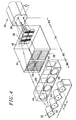
- Figure 4 illustrates schematically application of the present invention to connection a multi-core optical fiber 28, having four cores 30, to a strip 32 of four optical fibers 34 standard single modes which each have only one heart.
- connection device according to present invention which is schematically shown in Figure 4, includes four sets of elements micro-optics.
- sets 36 and 38 are formed on two sides planes, parallel and opposite of the same substrate parallelepiped 44 which is transparent to light from the hearts of the fiber 28.
- assemblies 40 and 42 are formed on two flat, parallel and opposite faces of the same parallelepipedic substrate 46 which is transparent to this light.
- the first set 36 is a set of micro-prisms 48.
- micro-prisms there are four micro-prisms in the example represented and they are respectively associated with four fiber hearts 28.
- micro-prisms 48 have the function of angularly separate the light beams respectively from the hearts 30 of the fiber 28 of so that we can let them diverge enough to obtain a space x band product compatible with the use of diffractive micro-optical elements, without overlapping of the light beams from different hearts.
- Figure 5 shows in cross section schematic the fiber 28 of which we see two of the hearts 30 as well as the two light beams 50 respectively from these hearts 30, in the absence of micro-prism at following fiber 28.
- the optical field C1 being of around 40 ⁇ m.
- micro-prisms 48 ( Figure 6), these micro-prisms allow the separation of the beams 50 and one obtains at a determined distance from micro-prisms 48 a field C2 optics of the order of 500 ⁇ m.
- the use of the set 36 of micro-prisms 48 allows the second set to be used 38 formed of diffractive elements 52 and the third assembly 40 also formed of diffractive elements 54.
- Sets 38 and 40 are holograms formed of elementary holograms which constitute elements 52 and 54 respectively.
- the holograms 52 of the set 38 are respectively associated with holograms 54 of the set 40.
- the fourth set 42 of micro-optical elements is made up of 56 micro-lenses which are respectively associated with the doublets mentioned more high and intended to optimize the optical coupling in fibers 34.
- micro-lenses diffractive or refractive microlenses can be used.
- the choice is made according to criteria such as efficiency, technological compatibility and the ease of miniaturization.
- micro-lens 58 In place of the first set 36 composed of micro-optical elements 48 one can use a micro-lens 58 as schematically illustrated by figure 7.
- This micro-lens 58 can be refractive or even diffractive.
- this micro-lens 58 can be convergent or divergent.
- the light beams 50 from cores 30 of multicore fiber 28 intersect at the exit from this micro-lens 58 and separate at new before the set 38 of diffractive elements.
- the device object of the invention can be used to achieve a type 1 distribution function to N.
- diffractive elements can be determined so as to distribute the light coming out of a multi-core fiber core on multiple areas of the output component and, for example, to inject this light into several fibers of the bar.
- Light distribution can be done equally or unevenly and the number of areas of the output component may be different from the number of hearts of multi-core fiber.
- the present invention can also be used to perform an N to 1 type "fusion" function.
- the diffractive elements can be designed to direct light from multiple cores of the multicore fiber in the same output component area, for example in the same optical fiber from a fiber optic strip single-mode.
- the contributions from different hearts of the multicore fiber can be done in equal parts or uneven.
- the number of zones of the output component may be different from the number of cores in the fiber multicore.
- a device conforming to the invention such as that of Figure 4 can be used "backwards", for example to connect, to a multicore fiber, a strip or a matrix of single-mode optical fibers (single core) or flat optical guides or light sources such as VCSELs.
- the light coming out of the fibers of the bar (or matrix or plan guides or VCSELs for example) is then injected into the hearts multi-core fiber.
- the sets of diffractive elements and the sets of refractive elements can be respectively made on independent substrates and mounted as an elementary photographic lens multiple.
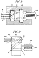
- these assemblies are produced per pair, the two sets of the same pair being made on two opposite sides of the same substrate transparent as illustrated schematically the Figure 4 and Figure 8.
- Figure 8 shows in fact the different components of figure 4.
- the sets of diffractive elements and the sets of refractive elements can also be all made on the same transparent substrate at the light from the hearts of fiber optics multicore.
- the light then makes one or more back and forth inside the substrate thanks to reflective treatments provided for this purpose and applied to this substrate.
- the sets 36 and 40 are arranged on a first face of the substrate 62, the assembly 36 is facing fiber 28.
- the assemblies 38 and 42 are arranged on a second face of the substrate 62, the assembly 42 is found next to component 32.
- the relative positions of the sets 36, 38, 40 and 42 are such that the light beams from the hearts of fiber 28 cross the whole 36 (and interact with it) then cross the substrate 62, are reflected on the assembly 38 (and are diffracted by it), cross the substrate 62, are reflected on the assembly 40 (and are diffracted by it), still cross a times the substrate 62 then cross the assembly 42 (in interacting with it) and eventually reach component 32.
- the device according to the invention which is schematically shown in Figure 9, is particularly interesting because it allows to postpone problems of "alignment" of the various organs which make up on technological achievement and allows also to reduce the number of interfaces and therefore losses due to reflections.
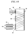
- Figure 10 schematically illustrates a variant of the device of FIG. 9.
- the sets 36 and 42 operate by transmission and are trained (engraved) on the first face of the substrate 62.
- Fiber 28 is still next to the set 36.
- Component 32 is still opposite of the set 42.
- the second face of the substrate 62 is covered with a reflective layer 64.
- the device of Figure 10 comprises a set 66 of diffractive micro-optical elements operating by reflection.
- This set 66 is placed on the first face of the substrate 62, between the assemblies 36 and 42.
- the relative positions of the sets 36, 66 and 42 are such that the light beams from cores of the fiber 28 cross the assembly 36 (and interact with it) and then cross the substrate 62, are reflected on the layer 64, cross the substrate 62 again, reflect on set 66 (and are diffracted by it), once again cross the substrate 62, cross again this one after reflection on layer 64 then cross the assembly 42 (interacting with it) and finally reach component 32.
- the fabrication of the device of the figure 10 is simpler than that of the device in FIG. 9 because, in the case of FIG. 10, it is not necessary to align micro-optics on both faces of substrate 62.
- the installation of the device does not require while some welds, splices or connections if the output fibers 34 have connectors optical.
- the present invention encompasses all possible combinations of these variants.
Landscapes
- Physics & Mathematics (AREA)
- General Physics & Mathematics (AREA)
- Optics & Photonics (AREA)
- Optical Couplings Of Light Guides (AREA)
- Diffracting Gratings Or Hologram Optical Elements (AREA)
Applications Claiming Priority (2)
| Application Number | Priority Date | Filing Date | Title |
|---|---|---|---|
| FR9612240A FR2754354B1 (fr) | 1996-10-08 | 1996-10-08 | Dispositif de connexion pour fibre optique multicoeur, a base d'elements optiques en espace libre |
| FR9612240 | 1996-10-08 |
Publications (1)
| Publication Number | Publication Date |
|---|---|
| EP0836103A1 true EP0836103A1 (de) | 1998-04-15 |
Family
ID=9496457
Family Applications (1)
| Application Number | Title | Priority Date | Filing Date |
|---|---|---|---|
| EP97402342A Ceased EP0836103A1 (de) | 1996-10-08 | 1997-10-06 | Verbindungsvorrichtung für optische Mehrkernfaser bestehende aus optischen Elementen in freien Raum |
Country Status (3)
| Country | Link |
|---|---|
| US (1) | US6078708A (de) |
| EP (1) | EP0836103A1 (de) |
| FR (1) | FR2754354B1 (de) |
Cited By (2)
| Publication number | Priority date | Publication date | Assignee | Title |
|---|---|---|---|---|
| WO2001077725A3 (en) * | 2000-04-10 | 2002-06-13 | Lightchip Inc | Wavelength division multiplexing/demultiplexing devices employing patterned optical components |
| EP2518549A1 (de) * | 2011-04-26 | 2012-10-31 | Alcatel Lucent | Räumlicher Multiplexer zur Kopplung von Einzelmodusfasern an eine Mehrkernfaser |
Families Citing this family (16)
| Publication number | Priority date | Publication date | Assignee | Title |
|---|---|---|---|---|
| US7142749B2 (en) | 2001-06-27 | 2006-11-28 | Finisar Corporation | System and method for controlling spectral passband profile |
| AU2002323522A1 (en) * | 2001-08-29 | 2003-03-18 | 3M Innovative Properties Company | Optical devices using shaped optical fibers and methods for making optical devices with shaped optical fibers |
| US6928226B2 (en) * | 2002-03-14 | 2005-08-09 | Corning Incorporated | Fiber and lens grippers, optical devices and methods of manufacture |
| GB0211445D0 (en) * | 2002-05-18 | 2002-06-26 | Qinetiq Ltd | Fibre optic connector |
| US7076129B2 (en) * | 2003-04-30 | 2006-07-11 | Lemoff Brian E | Apparatus and method for a filterless parallel WDM multiplexer |
| US7016018B2 (en) * | 2003-06-04 | 2006-03-21 | Fuji Photo Film Co., Ltd. | Exposure device |
| FR2860599B1 (fr) * | 2003-10-03 | 2006-02-03 | Ensmse | Dispositif de couplage optique d'une fibre monomode multi-coeurs, et procede de fabrication correspondant |
| US9341828B2 (en) | 2011-03-31 | 2016-05-17 | Globalfoundries Inc. | Multi-core fiber optical coupling elements |
| US9069143B2 (en) * | 2010-03-16 | 2015-06-30 | Ofs Fitel, Llc | Multifiber connectors for multicore optical fiber cables |
| US8488921B2 (en) | 2010-07-16 | 2013-07-16 | International Business Machines Corporation | Packaged multicore fiber optical transceiver module |
| CA2787565A1 (en) * | 2011-08-24 | 2013-02-24 | Nistica, Inc. | Asymmetric lenslet array |
| US9322987B2 (en) | 2013-08-27 | 2016-04-26 | International Business Machines Corporation | Multicore fiber coupler between multicore fibers and optical waveguides |
| ES3023849T3 (en) * | 2019-06-03 | 2025-06-03 | Alcon Inc | Aligning multi-wavelength laser beams with cores of a multi-core fiber |
| JPWO2022137632A1 (de) * | 2020-12-23 | 2022-06-30 | ||
| CN115826135A (zh) * | 2021-09-18 | 2023-03-21 | 华为技术有限公司 | 一种激光传输装置及离子阱系统 |
| WO2023176085A1 (ja) * | 2022-03-17 | 2023-09-21 | 住友電気工業株式会社 | マルチコア光ファイバ、光コンバイナ、およびファイバ特性測定方法 |
Citations (2)
| Publication number | Priority date | Publication date | Assignee | Title |
|---|---|---|---|---|
| US5241612A (en) * | 1991-09-17 | 1993-08-31 | Fujitsu Limited | Multicore optical connector |
| WO1994019712A1 (en) * | 1993-02-26 | 1994-09-01 | Yeda Research & Development Co., Ltd. | Holographic optical devices |
Family Cites Families (4)
| Publication number | Priority date | Publication date | Assignee | Title |
|---|---|---|---|---|
| JPS60112203U (ja) * | 1984-01-05 | 1985-07-30 | 住友電気工業株式会社 | 光伝送用多心フアイバ |
| KR880003203A (ko) * | 1986-08-05 | 1988-05-14 | 나까하라 쯔네오 | 광파이버 심선 |
| FR2701571B1 (fr) * | 1993-02-15 | 1995-03-17 | Georges Le Noane | Guides optiques multicÓoeurs de grande précision et de petites dimensions et procédé de fabrication de ces guides. |
| FR2727529B1 (fr) * | 1994-11-28 | 1997-01-03 | France Telecom | Dispositif de diffraction de lumiere utilisant des modulateurs spatiaux de lumiere reconfigurables et l'effet talbot fractionnaire |
-
1996
- 1996-10-08 FR FR9612240A patent/FR2754354B1/fr not_active Expired - Fee Related
-
1997
- 1997-10-04 US US08/944,081 patent/US6078708A/en not_active Expired - Fee Related
- 1997-10-06 EP EP97402342A patent/EP0836103A1/de not_active Ceased
Patent Citations (2)
| Publication number | Priority date | Publication date | Assignee | Title |
|---|---|---|---|---|
| US5241612A (en) * | 1991-09-17 | 1993-08-31 | Fujitsu Limited | Multicore optical connector |
| WO1994019712A1 (en) * | 1993-02-26 | 1994-09-01 | Yeda Research & Development Co., Ltd. | Holographic optical devices |
Non-Patent Citations (2)
| Title |
|---|
| JAHNS J ET AL: "PARALLEL OPTICAL INTERCONNECTIONS USING SURFACE-EMITTING MICROLASERS AND A HYBRID IMAGING SYSTEM", OPTICS COMMUNICATIONS, vol. 109, no. 3/04, 1 July 1994 (1994-07-01), pages 328 - 337, XP000448151 * |
| O'BRIEN D C ET AL: "DYNAMIC HOLOGRAPHIC INTERCONNECTS THAT USE FERROELECTRIC LIQUID-CRYSTAL SPATIAL LIGHT MODULATORS", APPLIED OPTICS, vol. 33, no. 14, 10 May 1994 (1994-05-10), pages 2795 - 2803, XP000442243 * |
Cited By (3)
| Publication number | Priority date | Publication date | Assignee | Title |
|---|---|---|---|---|
| WO2001077725A3 (en) * | 2000-04-10 | 2002-06-13 | Lightchip Inc | Wavelength division multiplexing/demultiplexing devices employing patterned optical components |
| US6594415B1 (en) | 2000-04-10 | 2003-07-15 | Confluent Photonics Corporation | Wavelength division multiplexing/demultiplexing devices employing patterned optical components |
| EP2518549A1 (de) * | 2011-04-26 | 2012-10-31 | Alcatel Lucent | Räumlicher Multiplexer zur Kopplung von Einzelmodusfasern an eine Mehrkernfaser |
Also Published As
| Publication number | Publication date |
|---|---|
| US6078708A (en) | 2000-06-20 |
| FR2754354A1 (fr) | 1998-04-10 |
| FR2754354B1 (fr) | 1998-11-06 |
Similar Documents
| Publication | Publication Date | Title |
|---|---|---|
| EP0836103A1 (de) | Verbindungsvorrichtung für optische Mehrkernfaser bestehende aus optischen Elementen in freien Raum | |
| EP3610309B1 (de) | Photonischer chip mit integrierter kollimationsstruktur | |
| CN102483497B (zh) | 光学互连件 | |
| EP0670507B1 (de) | Verfahren zur Bildung einer optischen Mehrweg-Verbindungsanordnung, insbesondere für optische Fasern | |
| FR3077652A1 (fr) | Puce photonique a structure de collimation integree | |
| EP3491438B1 (de) | Multispektraler optischer koppler mit niedrigen empfangsverlusten | |
| FR3074587A1 (fr) | Puce photonique a repliement de trajet optique et structure de collimation integree | |
| EP3339924A1 (de) | Optimierter integrierter photonenschaltkreis | |
| FR3066617A1 (fr) | Puce photonique a structure reflechissante de repliement de trajet optique | |
| EP4102273A1 (de) | Integrierte optische komponente mit einem verbreiterten lichtstrahl | |
| FR2655430A1 (fr) | Coupeur optique et systeme informatique a processeurs repartis. | |
| FR2477287A2 (fr) | Repartiteur optique multiple de la lumiere, procede de realisation d'un filtre interferentiel pour un tel repartiteur et mise en oeuvre de ce repartiteur | |
| FR2749672A1 (fr) | Positionnement vertical d'un composant optoelectronique sur un support, en regard d'un guide optique integre a ce support | |
| CA2160217C (fr) | Coupleur optique selectif en longueur d'onde | |
| US6493484B1 (en) | Optical add/drop filter for wavelength division multiplexed systems | |
| EP3987337B1 (de) | Lichtquelle mit mindestens einem halbleiterchip mit mindestens eine diode | |
| FR3077889A1 (fr) | Dispositif optique de compensation des imperfections des composants optiques composant le dispositif et procede de fabrication d'un tel dispositif | |
| EP4372435B1 (de) | Photonischer chip und infrarot-abbildungssystem mit einem solchen photonischen chip | |
| FR2756056A1 (fr) | Dispositif de positionnement et de maintien de composants optiques | |
| EP0416989B1 (de) | Kopplungsvorrichtung zwischen optischen Übertragungselementen | |
| EP4390483A1 (de) | Optische kopplungsvorrichtung mit holographischer beugungsstruktur | |
| Patel et al. | WDM filter modules in compact, low-cost plastic packages for byte-wide multimode fibre ribbon cable data links | |
| EP1625435A1 (de) | Integrierte photonische schaltung mit zwischenverbindungsmitteln zur verbindung mit optoelektronischen komponenten | |
| FR2570840A1 (fr) | Coupleur optique | |
| WO2024022871A1 (fr) | Fibre optique comportant un réseau de bragg |
Legal Events
| Date | Code | Title | Description |
|---|---|---|---|
| PUAI | Public reference made under article 153(3) epc to a published international application that has entered the european phase |
Free format text: ORIGINAL CODE: 0009012 |
|
| AK | Designated contracting states |
Kind code of ref document: A1 Designated state(s): DE GB |
|
| 17P | Request for examination filed |
Effective date: 19980921 |
|
| AKX | Designation fees paid |
Free format text: DE GB |
|
| RBV | Designated contracting states (corrected) |
Designated state(s): DE GB |
|
| 17Q | First examination report despatched |
Effective date: 20030606 |
|
| STAA | Information on the status of an ep patent application or granted ep patent |
Free format text: STATUS: THE APPLICATION HAS BEEN REFUSED |
|
| 18R | Application refused |
Effective date: 20040515 |