EP0836162B1 - Waage in einem Spiel-, Vergnügungs- oder Verkaufsautomaten - Google Patents
Waage in einem Spiel-, Vergnügungs- oder Verkaufsautomaten Download PDFInfo
- Publication number
- EP0836162B1 EP0836162B1 EP98100070A EP98100070A EP0836162B1 EP 0836162 B1 EP0836162 B1 EP 0836162B1 EP 98100070 A EP98100070 A EP 98100070A EP 98100070 A EP98100070 A EP 98100070A EP 0836162 B1 EP0836162 B1 EP 0836162B1
- Authority
- EP
- European Patent Office
- Prior art keywords
- coin
- coins
- hopper
- count
- weight
- Prior art date
- Legal status (The legal status is an assumption and is not a legal conclusion. Google has not performed a legal analysis and makes no representation as to the accuracy of the status listed.)
- Expired - Lifetime
Links
- 238000005303 weighing Methods 0.000 title claims description 70
- 238000000034 method Methods 0.000 claims description 72
- 238000001514 detection method Methods 0.000 claims description 11
- 125000006850 spacer group Chemical group 0.000 claims description 5
- 238000003780 insertion Methods 0.000 claims description 4
- 230000037431 insertion Effects 0.000 claims description 4
- 230000001133 acceleration Effects 0.000 claims 3
- 230000008569 process Effects 0.000 description 48
- BWSIKGOGLDNQBZ-LURJTMIESA-N (2s)-2-(methoxymethyl)pyrrolidin-1-amine Chemical compound COC[C@@H]1CCCN1N BWSIKGOGLDNQBZ-LURJTMIESA-N 0.000 description 9
- 230000008859 change Effects 0.000 description 9
- 230000007812 deficiency Effects 0.000 description 6
- 230000006870 function Effects 0.000 description 6
- 230000000737 periodic effect Effects 0.000 description 5
- 230000000694 effects Effects 0.000 description 4
- 238000012544 monitoring process Methods 0.000 description 4
- 238000012423 maintenance Methods 0.000 description 3
- 238000003825 pressing Methods 0.000 description 3
- 238000004891 communication Methods 0.000 description 2
- 230000001934 delay Effects 0.000 description 2
- 238000005259 measurement Methods 0.000 description 2
- 230000007246 mechanism Effects 0.000 description 2
- 230000000717 retained effect Effects 0.000 description 2
- 241000167854 Bourreria succulenta Species 0.000 description 1
- 208000001613 Gambling Diseases 0.000 description 1
- 241000237858 Gastropoda Species 0.000 description 1
- 206010000210 abortion Diseases 0.000 description 1
- 230000003213 activating effect Effects 0.000 description 1
- 238000013459 approach Methods 0.000 description 1
- 235000019693 cherries Nutrition 0.000 description 1
- 230000006835 compression Effects 0.000 description 1
- 238000007906 compression Methods 0.000 description 1
- 230000001186 cumulative effect Effects 0.000 description 1
- 230000001627 detrimental effect Effects 0.000 description 1
- 238000010586 diagram Methods 0.000 description 1
- 230000001667 episodic effect Effects 0.000 description 1
- 230000008570 general process Effects 0.000 description 1
- 238000009434 installation Methods 0.000 description 1
- 230000002452 interceptive effect Effects 0.000 description 1
- 235000021018 plums Nutrition 0.000 description 1
- 238000012545 processing Methods 0.000 description 1
- 238000007789 sealing Methods 0.000 description 1
- 239000004065 semiconductor Substances 0.000 description 1
- 238000012360 testing method Methods 0.000 description 1
Images




Classifications
-
- G—PHYSICS
- G07—CHECKING-DEVICES
- G07F—COIN-FREED OR LIKE APPARATUS
- G07F17/00—Coin-freed apparatus for hiring articles; Coin-freed facilities or services
- G07F17/32—Coin-freed apparatus for hiring articles; Coin-freed facilities or services for games, toys, sports, or amusements
- G07F17/3244—Payment aspects of a gaming system, e.g. payment schemes, setting payout ratio, bonus or consolation prizes
- G07F17/3248—Payment aspects of a gaming system, e.g. payment schemes, setting payout ratio, bonus or consolation prizes involving non-monetary media of fixed value, e.g. casino chips of fixed value
-
- G—PHYSICS
- G01—MEASURING; TESTING
- G01G—WEIGHING
- G01G19/00—Weighing apparatus or methods adapted for special purposes not provided for in the preceding groups
- G01G19/40—Weighing apparatus or methods adapted for special purposes not provided for in the preceding groups with provisions for indicating, recording, or computing price or other quantities dependent on the weight
- G01G19/42—Weighing apparatus or methods adapted for special purposes not provided for in the preceding groups with provisions for indicating, recording, or computing price or other quantities dependent on the weight for counting by weighing
-
- G—PHYSICS
- G01—MEASURING; TESTING
- G01G—WEIGHING
- G01G23/00—Auxiliary devices for weighing apparatus
- G01G23/18—Indicating devices, e.g. for remote indication; Recording devices; Scales, e.g. graduated
- G01G23/36—Indicating the weight by electrical means, e.g. using photoelectric cells
- G01G23/37—Indicating the weight by electrical means, e.g. using photoelectric cells involving digital counting
- G01G23/3728—Indicating the weight by electrical means, e.g. using photoelectric cells involving digital counting with wireless means
-
- G—PHYSICS
- G07—CHECKING-DEVICES
- G07F—COIN-FREED OR LIKE APPARATUS
- G07F17/00—Coin-freed apparatus for hiring articles; Coin-freed facilities or services
- G07F17/32—Coin-freed apparatus for hiring articles; Coin-freed facilities or services for games, toys, sports, or amusements
-
- G—PHYSICS
- G07—CHECKING-DEVICES
- G07F—COIN-FREED OR LIKE APPARATUS
- G07F17/00—Coin-freed apparatus for hiring articles; Coin-freed facilities or services
- G07F17/32—Coin-freed apparatus for hiring articles; Coin-freed facilities or services for games, toys, sports, or amusements
- G07F17/3225—Data transfer within a gaming system, e.g. data sent between gaming machines and users
- G07F17/3232—Data transfer within a gaming system, e.g. data sent between gaming machines and users wherein the operator is informed
- G07F17/3234—Data transfer within a gaming system, e.g. data sent between gaming machines and users wherein the operator is informed about the performance of a gaming system, e.g. revenue, diagnosis of the gaming system
-
- G—PHYSICS
- G07—CHECKING-DEVICES
- G07F—COIN-FREED OR LIKE APPARATUS
- G07F17/00—Coin-freed apparatus for hiring articles; Coin-freed facilities or services
- G07F17/32—Coin-freed apparatus for hiring articles; Coin-freed facilities or services for games, toys, sports, or amusements
- G07F17/3241—Security aspects of a gaming system, e.g. detecting cheating, device integrity, surveillance
-
- G—PHYSICS
- G07—CHECKING-DEVICES
- G07F—COIN-FREED OR LIKE APPARATUS
- G07F9/00—Details other than those peculiar to special kinds or types of apparatus
- G07F9/08—Counting total of coins inserted
Definitions
- the present invention relates to a weighing apparatus in a gaming, vending or amusement machine and to a method of coin theft detection in a gaming, amusement or vending machine comprising such a weighing apparatus.
- This kind of machines comprises coin hoppers which are used to collect and distribute coins in gaming, amusement and vending machines, were it is usual to determine the number of coins in a hopper by weighing the hopper and using the collected hopper weight information to deter fraud and theft.
- slot machines have been a popular attraction at gambling casinos and other gaming establishments.
- Such slot machines typically have a colorful display of gaming indicia, such as cherries, plums, oranges, sevens, etc. arrayed in rows and columns across the front of the slot machine.
- gaming indicia can be spun into motion for game play by the insertion of a coin into the slot machine and pulling the slot machine handle.
- the inserted coin is collected in a coin reservoir within the slot machine called a "hopper".
- the inserted coin will be retained in the hopper if there is a losing combination of gaming indicia shown or, alternatively, may be returned from the hopper to the slot machine player, perhaps with additional coins, if there is a winning combination of gaming indicia shown.
- slot machine hoppers Periodically, slot machine hoppers must be serviced by casino technicians. For example, the hopper may have too few or too many coins and must have its contents adjusted appropriately. Also, coins might be jammed in parts of the hopper in such a way that the hopper cannot function properly. If so inclined, a dishonest technician can pilfer a few coins each time he services a slot machine. While each individual instance of such pilfering may not represent a significant threat to a casino's bottom line, the cumulative loss over time from such pilfering can be quite large. Casinos have tried to combat this problem by, among other things, assigning two or more technicians to each task requiring a slot machine to be opened. However, this approach leads to additional labor costs and may not even help if each of the assigned technicians is dishonest.
- Coins can be pilfered from slot machines hoppers not only by casino technicians but also by the slot machine players. For example, a player might attach a string to the coin he is inserting into the slot machine so that he can retrieve the coin from the slot machine by simply pulling the string after the coin has been erroneously counted as "received" by the slot machine and game play has begun. Also, the player might try to jam the payout counter after receiving a winning combination so that the slot machine continues
- the present invention provides a weighing apparatus in a gaming, amusement or vending machine of claim 1.
- Prefered embodiments are defined by claims 2 and 3.
- the weighing apparatus may be constructed integrally with the coin hopper assembly and fits between the coin hopper and its base plate.
- the weighing apparatus is constructed separately from the coin hopper assembly.
- the weighing apparatus includes upper and lower plates which are separated by one or more weighing instruments, such as load cells with strain gauges. In operation, the lower plate of this weighing apparatus is typically placed against the floor of the slot machine and the hopper is then simply placed on top of the weighing apparatus' upper plate.
- the present invention also provides a method of coin theft detection of claim 4 comprising the weighing apparatus of claim 1.
- Preferred embodiments are defined by claims 5 to 14.
- the weighing apparatus may take periodic readings of the number of coins residing in the hopper and can communicate those readings.
- the unauthorized removal of coins during an actual or purported technician maintenance procedure can be detected by determining a count of coins by weight when the slot machine door is opened, determining a count of coins by weight once the slot machine door is closed, and using those two counts to determine the change in the number of coins in the hopper at the time of servicing.
- the identity of the person opening the hopper door and the time at which the hopper door is opened and closed can be recorded, along with any detected discrepancy.
- the calculation of any detected discrepancy may take into account an expected change in coin count. An expected change in coin count would exist when a technician is asked to open the machine and either remove or insert coins.
- a similar method can also be used to detect a player's theft of coins from the slot machine.
- the actual number of coins in the hopper can be determined by weight and compared with the expected number of coins in the hopper in order to determine if the player has inappropriately been withholding or taking coins from the slot machine. If any unexpected coin discrepancy is detected by the weighing apparatus of the present invention, it can be communicated to appropriate security personnel in real time through a computer hook-up or alarm or, alternatively, communicated periodically through downloading of stored hopper weight information.
- FIG. 1 is a front view of a slot machine with its door open showing a coin hopper and integrated weighing apparatus of the present invention.
- FIG. 2 is a more detailed side view of the coin hopper shown in FIG. 1 illustrating the cantilevered mounting of the integrated weighing apparatus of the present invention onto the coin hopper, load cells.
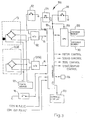
- FIG. 3 is a schematic diagram of the accompanying electronics for the weighing apparatuses shown in FIGS. 1-2.
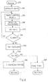
- FIG. 4 is a flowchart of an accounting process for to detect coin hopper theft in a timely manner.
- FIG. 5 is a flowchart of a process for automatically taking periodic measurements to determine a coin count in the hopper.
- FIG. 6 is a flowchart of a process for calibrating a hopper's tare weight and a per coin weight.
- FIG. 7 is a flowchart of a process for obtaining an accurate hopper weight during calibration in the presence of noise and/or vibrations.
- FIG. 8 is a flowchart of a process for obtaining an accurate coin count in the presence of noise and/or vibrations.
- FIG. 1 illustrates a coin hopper assembly 9 in a slot machine 1 which incorporate an integrated form of coin weighing apparatus 12 of the present invention.
- This coin hopper assembly 9 includes a coin hopper 10 , hopper base plate 14 and integrated coin weighing apparatus 12 .
- the hopper door 2 of slot machine 1 is shown in an open position. Nonetheless, during operation, the hopper door 2 would usually be locked shut to prevent theft of coins.
- coin hopper 10 is often placed below a coin insertion slot 3 and above a coil payout tray 4 .
- a player would insert one or more coins into coin insertion slot 3 and those coins would drop into coin hopper 10.
- the coins would typically pass through a coin handling unit on their way to coin hopper 10 .
- This coin handling unit performs tests (size, weight, angular momentum, etc.) to determine if the coin is real and of the proper denomination.
- the coin handling unit, or other device would provide a signal, such as an electric "coin in” pulse, to a logic board to indicate that a valid coin has been inserted (See, FIG . 9) .
- coin hopper 10 ejects the correct amount of coins from ejection slot 5 into payout tray 4 .
- the hopper 10 is actually located below the payout tray and an "elevator” or “escalator” mechanism is used to raise the paid out coins higher than the payout tray so that the coins will fall into the payout tray, and thus be accessible to the player.
- a motorized conveyor assembly (not shown) of coin hopper 10 causes coins to be ejected to the payout tray or elevator and that conveyor assembly runs until a "coin out” counter indicates that the correct number of coins have been ejected.
- FIG. 2 provides a close-up view of how the integrated form of coin weighing apparatus 12 of FIG. 1 is mounted in the coin hopper assembly 9.
- the coin weighing apparatus 12 includes a load cell 13 and strain gauge 18 .
- This coin weighing apparatus 12 is mounted between the coin hopper 10 and hopper base plate 14 .
- the coin weighing apparatus 12 is affixed to the coin hopper 10 by a cantilevered spacer 16(a) and an appropriate fastener 17 .
- the coin weighing apparatus 12 is also affixed to the hopper base plate 14 by a cantilevered spacer 16(b) and an appropriate fastener (not shown).
- coin hopper 10 is totally supported by cantilever spacer 16(a), which is in turn totally supported by coin weighing apparatus 12 , which is turn totally supported by cantilever spacer 16(b) mounted directly to base 14 .
- the weight of the coin hopper 10 and its coins is applied to the load cell 13 of the coin weighing apparatus 12 causing a strain on the load cell 13 which is a function of the weight of the coin hopper 10 and its coins. That strain is measured by a strain gauge 18 and electrically conveyed to a suitable electronic monitoring apparatus (not shown) by the lines of cabling 20 .
- load cell 12 might suitably be a Model 1040 digital load cell or Model 1041 analog load cell manufactured by Tedea Huntleigh of Canoga Park, California.
- the load cell 12 might suitably be a 36-kilogram analog load cell sold by HBM, Inc. of Connecticut with a Cirrus Logic strain gauge sensor.
- a 72-kilogram analog load cell sold by HBM, Inc. might be used. Compression, sub-miniature and strip sensor types of load cells may suitably be used with the weighing apparatus of the present invention.
- the coin weighing apparatus 12 shown in FIGS. 1 and 2 is referred to as "integrated" into the coin hopper assembly 9 because it is situated between the coin hopper 10 and hopper base plate 14 .
- installation of this integrated form of coin weighing apparatus 12 typically involves removing the coin hopper assembly 9 from the slot machine 1 and separating the coin hopper 10 from the hopper base plate 14.
- the coin weighing apparatus 12 can then be integrated into the coin hopper assembly 9 by affixing it to the coin hopper 10 and hopper base plate 14 as shown in FIG. 2 .
- the logic board comprises an analog-to-digital converter 102 (A/D) coupled to load cell 13 to convert a load signal from an analog signal to a digital load cell sample.
- A/D analog-to-digital converter
- the digital load cell sample has a resolution of 20 bits, but other resolution analog-to-digital converters can also be used (e.g., 14 bits or greater).
- an integer corresponding to the digital load cell sample can range from 0 to 16,383.
- A/D 102 provides its output to an input-output (I/O) controller 104 which in turn provides samples, as requested, to a central processing unit (CPU) 106.
- I/O controller for the present invention would be a 75HCT245 chip.
- CPU 106 executes programs stored in program memory 108 and uses a variable memory 110 to store data incident to the execution of those programs.
- the programs executed by CPU 106 comprise instructions for following the processes described in FIGS. 4-8 , however CPU 106 might also execute other programs not described herein.
- a CPU with built-in I/O control functions and/or memory might be used, however the description of FIG. 3 still applies to such integrated systems.
- FIG. 3 shows a number of I/O signals being provided to, or by, I/O controller 104 .
- I/O controller 104 For example, "Coin In” and “Coin Out” signals are provided from coin handling devices. These signals can be pulses (one pulse per coin) or can be other signals indicating a count, as are well known in the art.
- I/O controller 104 might also provide motor, sound, reel, lights and display control signals, if CPU 106 or I/O controller 104 are programmed to handle such functions of slot machine 1.
- I/O controller 104 receives switch signals from a variety of sources, of which a calibration switch 112 , a start switch 114 , a reset switch 116 and a door switch 118 are shown.
- FIG. 3 also shows an internal display 120 .
- a drop box is a standard part of some slot machines and is used to contain the overflow of coins from a hopper.
- a drop box might have been installed below coin hopper 10 .
- a drop box is similar to a hopper, in that it holds a collection of coins, but differs from a hopper in that coins are not ejected from the drop box. If a drop box is used, a hopper may have a sensor, such as a coin weighing apparatus of the present invention, which detects when the hopper is full.
- Drop box load cell 13(a) performs a function similar to the coin hopper load cell 13 insofar as it provides an indication of the weight of a drop box (not shown) and the coins therein.
- This drop box load cell 13(a) may preferably be configured in any of the ways previously described.
- a coin weighing apparatus of the present invention could be used to weigh coin fill bags which are stored in the slot machine to conveniently replenish empty coin hoppers as well as other types of drop containers. Theft or fraud can be detected by such a coin weighing apparatus when the weight of the fill bag changes without good cause.
- I/O controller 104 also reads/writes data from a data pin 124 (see FIG. 1 ).
- data pin 124 is part of a communication system manufactured by Dallas Semiconductor.
- a data wand (not shown) is a hand-held, battery-powered device with an internal computer which communicates with I/O controller 104 through a single signal line and chassis ground connection.
- a data wand can be used in conjunction with data pin 124 to calibrate the coin weighing apparatus 12, 22, 43, 50.
- FIG. 4 is a flowchart of a process for detecting coin fraud or theft by a service technician. This process is controlled by CPU 106 according to instructions stored in program memory 108. Each step in FIG. 4 is numbered with a sequential step number, except where noted. The process shown in FIG. 4 begins when hopper door 2 (see FIG . 1 ) is opened (S1).
- hopper door 2 is secured by an electronic switch, such as a solenoid 126 (see FIG. 1 ), which can only be activated by the technician or employee touching their assigned data wand to data pin 124.
- CPU 106 records an employee ID communicated from the data wand before activating solenoid 126 to open hopper door 2 .
- hopper door 2 can be opened by an ordinary key and the door opening can be detected by door switch 118 . In either case, a preferred embodiment records the time of opening.
- hopper door 2 When hopper door 2 is being opened (S1), or preferably just before hopper door 2 moves, a coin count (C) is obtained (S2) and the count is stored (S3) as the opening count (OC). If CPU 106 makes continuous, periodic readings, then the opening count (OC) might just be the most recent periodic reading before hopper door 2 was opened and after the last game was played.
- step S4 the door is monitored until it is closed, and another coin count is taken (S5).
- this second coin count is a reading taken after slot machine 1 has stabilized following the closing of the door.
- This coin count, C is stored (S6) as the closing count (CC).
- S7 an expected change count (EC) is determined.
- This expected change count is positive in the case where a technician is sent to a slot machine to add coins to a depleted hopper, is negative where the technician is sent to the slot machine to remove coins, and is zero where the technician is sent to the slot machine simply to perform maintenance.
- the expected change count might not be known at the time the coins are removed, but later determined after the technician turns over the coins removed from the slot machine.
- a deficiency can be easily calculated (S8), by subtracting the closing count (CC) from the opening count (OC) and adding the expected change count (EC). If the resulting deficiency (D) is not equal to zero (S9), then an alarm can be set (S10).
- the slot machine does not automatically determine the identification of the technician or other employee opening the slot machine, the setting of an alarm might result in a flashing light on the slot machine being immediately activated, so that the unauthorized removal of coins can be detected by a floor manager while the thief is still present at the machine.
- the slot machine detects the time of opening and closing as well as the identification of the person opening the machine, thereby allowing the deficiency to be easily traced to a specific employee.
- the slot machine will merely record the time of entry and the deficiency for later comparison to a log kept elsewhere showing which employees had access to which slot machines at which times.
- the alarm is not merely a local alarm in the form of a flashing light on the slot machine or the like, but is an alarm which is recorded by CPU 106 and is communicated to a central security station (not shown). Regardless of whether an alarm is set or not, the flow of the process returns to step S1, where it remains until the hopper door is again opened.
- While the process shown in FIG. 4 will detect unauthorized removal of coins when a hopper door 2 is open, it does not necessarily detect unauthorized removal of coins when hopper door 2 is closed.
- the latter type of unauthorized coin removal might arise when the dishonest employee or technician modifies the slot machine to eject or reroute coins out of the hopper 10 into other spaces inside slot machine 1 for later retrieval.
- This latter type of closed door removal may also occur when a dishonest player tampers with the coin in or coin out mechanisms of the slot machine.
- This manner of closed door theft can be counteracted by monitoring the rate at which coins fail to reach hopper 10 or fail to be counted as they are ejected by comparing hopper weight to the "coin in” or “coin out” pulses to the I/O controller 104 and CPU 106 (FIG. 3). Similarly, if a dishonest player inserts slugs or other types of counterfeit coins into the slot machine which have a different weight than valid coins, a comparison of the expected weight of valid coins in the coin hopper with the actual weight of counterfeit coins in the coin hopper can be used to detect this type of fraud.
- the slot machine activity is communicated to a central security station for easy monitoring and prompt detection of deficiencies.
- the automatic coin accounting process of FIG. 4 is a process which can be run independently of the coin counting processes shown elsewhere. The use of the present invention to handle other modes of theft or coin accounting should be apparent after reading this present description.
- FIG. 4 shows a process of deficiency detection
- FIG. 5 shows a more general process of taking a reading to calculate coin count C.
- the processes of FIG. 4 and the processes of FIG. 5 run asynchronously, with the process shown in FIG. 5 being a process of periodically taking a reading to update the current coin count while the process shown in FIG. 4 (more specifically steps S2 and S5) merely refers to an episodic coin count when the slot machine door 2 is opened or closed.
- the process shown therein begins with an initialization of the variables used (S21).
- the operator is prompted with "START" or a similar prompt, prompting the operator to begin the calibration process.
- the prompt is displayed, in some embodiments, on a computer terminal, while in other embodiments it is displayed on an internal display 120 coupled to I/O 104 (see FIG . 3 ).
- the operator first determines that the hopper and slot machine are stable and the hopper is empty.
- CPU 106 determines whether diagnostics were requested by the operator.
- the operator signals that diagnostics are requested by sending a predetermined signal from a terminal to I/O controller 104 such as through the data pin I/O or by simultaneously pressing calibration button 112 and start button 114 (see FIG . 3 ). If diagnostics are requested, CPU 106 executes those diagnostics (S23) and proceeds to step S24. Otherwise, if diagnostics are not requested, CPU 106 proceeds directly to step S24.
- step S24 CPU 106 checks to see if the operator has requested a calibration.
- the operator requests calibration by pressing calibration button 112 . If calibration is requested, the calibration process is executed (S25) to determine a tare weight (TW) and a per coin weight (CW).
- TW tare weight
- CW per coin weight
- CPU 106 proceeds to step S26, where it determines whether or not the hopper was calibrated. If the hopper was not calibrated, either because calibration was not requested or because the calibration step was not successful due to unreliable readings, CPU 106 returns to step S24, thus creating a loop that is only exited when the hopper is finally calibrated.
- step S27 a reading of the hopper weight is taken and a coin count is calculated.
- This process is shown in further detail in FIG. 6.
- a reliable coin count is obtained (S28)
- that coin count is displayed, transmitted to a remote storage and/or display device or the coin count is simply stored in variable memory 110 (see FIG . 3 ) for later provision of a coin count value to other processes which use the coin count.
- CPU 106 returns to step S24.
- CPU 106 executes a periodic loop of taking a reading, calculating a coin count, and providing the coin count to various display or memory devices as needed.
- a latest reliable value for the coin count is retained and is not overwritten by any subsequent unreliable coin counts, thereby providing a reliable coin count value which can be polled at any time by asynchronous processes.
- FIG. 6 shows the calibration process of step S25 in further detail.
- CPU 10 6 waits ( S41) for a calibration signal, either from a remote device or from the operator pressing calibration switch 112 . If the calibration signal is not received within a predetermined time, the calibration process is aborted and an indication that calibration did not complete is given so that readings (see FIG. 5 ) will not be taken until the calibration process actually successfully completes. If the calibration signal is received, CPU 106 proceeds to obtain the hopper weight (S43), which is described in further detail in FIG. 7 . Prior to receipt of the calibration signal, the hopper should have been emptied by the operator so that a tare weight of the hopper can be obtained.
- a coin weight is calculated (S48) by subtracting the hopper tare weight (TW) from the just measured hopper weight (HW) and dividing the difference by N.
- This new per coin weight (CW) is then stored ( S49 ) in variable memory 110 , preferably compared with a known per coin weight, and, if the measured per coin weight favorably compares with the known per coin weight, the calibration process returns indicating a successful hopper calibration.
- FIG. 7 shows the process of getting a hopper weight, the result being either returning successfully with a hopper weight (HW) or returning an error indicating that the hopper was too unstable for a measurement to have been taken.
- HW hopper weight
- the variables used for temporary storage and loop control are initialized ( S60 ) and a sampled digital value, L, is taken from load cell 13 ( S61 ).
- L a sampled digital value
- FIGS. 4-8 are equally applicable to coin accounting using a drop box, with the main difference being that load cell 13(a) is sampled instead of load cell 13 .
- the sampled value L is stored as a reference reading R (S62), and a main loop is entered.
- the load cell is again sampled (S63) to obtain a new value for L. If the absolute value of the difference between L and the reference reading R is less than a variance limit, V, then the sampled value L is added to an accumulator (HW) and a loop counter (I) is incremented (S65).
- CPU 106 then pauses for a predetermined delay period of T1 milliseconds (S66) and then loops back to step S63 to take another reading. This continues until a predetermined number, C_SAMP, of readings has been taken. Once C_SAMP readings have been taken and accumulated, the value in the accumulator (HW) is divided by C_SAMP (S68), to yield a hopper weight.
- the operator is provided with an indication, such as a display "UNST", to indicate that instability is being detected, thereby giving the operator the opportunity to eliminate the source of instability while a reading is being taken. Assuming a valid hopper weight reading is obtained, this can be used in the calibration process shown in FIG. 6 .
- FIG. 8 shows the process of taking a reading, which results in either a coin count C being returned or an error indication being returned.
- an accumulator (HW) and a loop counter (not shown) are initialized.
- a load cell is sampled to obtain a value L
- CPU 106 delays for T2 milliseconds
- the sampled value L is added to the accumulator (HW).
- N_SAMP samples are taken.
- the hopper weight reading process of FIG. 8 is less interactive and less error-correcting than the hopper-weight reading process of FIG. 6 , since the former generally occurs when the slot machine is not open and an unreliable reading can be discarded without ill effects, whereas the latter process provides tare weight and per coin weights which cannot be as easily discarded.
- a hopper is weighed periodically and that weight is used, combined with an automatically determined per coin weight, to determine a number of coins in the hopper.
- coins are counted as the hopper door is opened and then counted again after the hopper door is closed and this difference is compared to an authorized difference to determine if unauthorized removal of coins from the hopper while the hopper door was open occurred.
- One application of this system includes a centralized slot machine control system, from where a trusted employee can monitor the opening and closing of each slot machine door, as well as a current inventory of the coins in the hopper and/or drop box of each slot machine. The necessary information can be communicated from the slot machines to the centralized slot machine control system through dedicated communication lines running fron each slot machine or can be provided by the above described data pin system.
Landscapes
- Physics & Mathematics (AREA)
- General Physics & Mathematics (AREA)
- Engineering & Computer Science (AREA)
- Mathematical Physics (AREA)
- Theoretical Computer Science (AREA)
- Computer Security & Cryptography (AREA)
- General Engineering & Computer Science (AREA)
- Computer Networks & Wireless Communication (AREA)
- Slot Machines And Peripheral Devices (AREA)
- Control Of Vending Devices And Auxiliary Devices For Vending Devices (AREA)
Claims (19)
- Wägevorrichtung in einem Spiel- Unterhaltungs- oder Verkaufsautomaten, umfassend:dadurch gekennzeichnet, dasseine obere Platte, die einen Münzenspeicher (10) trägt;eine Basis (14);eine längliche Lastzelle (12), enthaltend einen Dehnungsmesser, der zwischen oberer Platte und Basis angeordnet und an beiden befestigt ist;Abstandstücke (16a, 16b), die zwischen der Lastzelle und der oberen Platte und der Basis angeordnet sind, wobeidie Lastzelle (12) die Form eines rechteckigen Prismas aufweist und diagonal gegenüberliegende Ränder der Lastzelle an der oberen Platte und an der Basis (14) befestigt sind,
die Lastzelle (12) mit ihrer langen Dimension im rechten Winkel zur Längsachse des Münzenspeichers angeordnet ist. - Wägevorrichtung nach Anspruch 1, wobei der Spiel-, Unterhaltungs- oder Verkaufsautomat ein Münzautomat ist, vorzugsweise ein Unterhaltungsautomat mit Auszahlungsfunktion.
- Wägevorrichtung nach Anspruch 1, wobei diese des weiteren einen mit dem Dehnungsmesser verbundenen Analog-Digitalwandler aufweist.
- Verfahren zur Münzdiebstahlentdeckung in einem Spiel-, Verkaufs- oder Unterhaltungsautomaten, wobei der Automat eine Wägevorrichtung nach Anspruch 1 enthält und das Verfahren folgende Schritte umfasst:einen ersten Wägeschritt zum Abwiegen der Münzen in einem Münzenspeicher des Spielautomaten unter Verwendung einer in den Münzenspeicher eingebauten Wägevorrichtung, womit ein erstes Gewicht ermittelt wird;einen erste Berechnungsschritt zur Ermittlung einer Anzahl von Münzen im Münzenspeicher auf Basis des ersten Gewichts, woraus sich eine erste Münzenzahl ergibt;Freigabe des Zugriffs auf die Münzen im Münzenspeicher;ein zweiter Wägeschritt zum Abwiegen der Münzen in einem Münzenspeicher des Spielautomaten unter Verwendung einer in den Münzenspeicher eingebauten Wägevorrichtung, wodurch ein zweites Gewicht ermittelt wird;ein zweiter Berechnungsschritt zur Ermittlung einer Anzahl von Münzen im Münzenspeicher auf Basis des zweiten Gewichts, woraus sich eine zweite Münzenzahl ergibt; undEinstellung eines Alarms, wenn die zweite Münzenzahl geringer ist als die erste Münzenzahl minus einer zulässigen Anzahl entnommener Münzen.
- Verfahren nach Anspruch 4, wobei der erste und zweite Schritt des Münzenwägens Schritte des Wägens von Münzen mit bekanntem Einheitsgewicht sind.
- Verfahren nach Anspruch 4, wobei der erste und der zweite Schritt des Münzenwägens Schritte des Wägens von Münzen und des Münzenspeichers sind.
- Verfahren nach Anspruch 4, wobei die Schritte des Münzenwägens folgende Teilschritte umfassen:Messen einer Beschleunigung des Münzenspeichers im Verhältnis zum Spielautomaten; undMessen einer Verformung eines Tragebalkens, der durch das Gewicht des Münzenspeichers und der darin enthaltenen Münzen verformt wird, wenn die Beschleunigung des Münzenspeichers im Verhältnis zum Spielautomaten im wesentlichen Null oder eine bekannte Beschleunigung ist.
- Verfahren nach Anspruch 4, umfassend die Schritte:Feststellen einer geöffneten Türe;im wesentlichen gleichzeitig mit dem Öffnen der Tür Messen einer ersten Münzenzahl im Münzenspeicher nach Gewicht unter Verwendung einer in den Münzenspeicher eingebauten Münzwägevorrichtung;Feststellen der geschlossenen Tür;Messen einer zweiten Münzenzahl im Münzenspeicher nach Gewicht, nachdem das Schließen der Tür festgestellt wurde, unter Verwendung einer in den Münzenspeicher eingebauten Münzwägevorrichtung; undFeststellen einer Differenz der Münzenzahl durch Subtrahieren der ersten Zahl von der zweiten Zahl und elektronische Meldung der Differenz an ein Diebstahlkontrollsystem.
- Verfahren nach Anspruch 8, wobei der Schritt der Meldung der Differenz den Schritt der Einstellung eines Alarms umfasst.
- Verfahren nach Anspruch 9, wobei der Schritt der Alarmeinstellung ein Schritt des Setzens einer Markierung in einem Feld einer Spalte einer mit dem Spielautomaten verbundenen Datentabelle ist, in dem die Differenz festgestellt wird.
- Verfahren nach Anspruch 4, umfassend die Schritte:Wägen der Münzen in einem Münzenspeicher des Spielautomaten unter Verwendung einer in den Münzenspeicher eingebauten Münzwägevorrichtung zur Bestimmung eines Basisgewichts am Beginn einer Erfassungsperiode;Berechnen einer Basismünzenzahl vom Basisgewicht;Feststellen einer Anzahl eingeworfener Münzen;Feststellen einer Münzenzahl für jede autorisierte Entnahme oder Auszahlung;Berechnen einer erwarteten Münzenzahl durch Subtrahieren der Münzenzahl für jede autorisierte Entnahme oder Auszahlung von der Basismünzenzahl und Addieren der dazu eingeworfenen Münzen;Wägen der Münzen im Münzenspeicher am Ende der Erfassungsperiode zur Feststellung eines abschließenden Münzenspeichergewichts unter Verwendung einer in den Münzenspeicher eingebauten Münzwägevorrichtung;Berechnen einer Münzenendzahl aus dem Endgewicht des Münzenspeichers; undFeststellen eines Diskrepanzbetrags für die Erfassungsperiode durch Subtrahieren der Münzenendzahl von der erwarteten Münzenzahl.
- Verfahren nach Anspruch 11, des weiteren umfassend den Schritt der Meldung des Diskrepanzbetrags als Münzendiebstahlsbetrag.
- Verfahren nach Anspruch 4 zur Feststellung eines Münzendiebstahls aus einer Nachfülltasche in dem Spiel-, Unterhaltungs- oder Verkaufsautomaten, umfassend die Schritte:erster Wägeschritt zum Abwiegen der Münzen in einer Nachfülltasche in dem Automaten;erster Berechnungsschritt zum Berechnen einer Anzahl von Münzen in der Nachfülltasche auf Basis des ersten Gewichts, woraus sich eine erste Münzenzahl ergibt;den Zugriff auf die Nachfülltasche ermöglichen;zweiter Wägeschritt zum Abwiegen der Münzen in der Nachfülltasche nach Gewährung des Zugriffes, dadurch Messen eines zweiten Gewichts;zweiter Berechnungsschritt zum Berechnen einer Anzahl von Münzen in der Nachfülltasche auf Basis des zweiten Gewichts, woraus sich eine zweite Münzenzahl ergibt; undEinstellen eines Alarms, wenn die zweite Münzenzahl weniger als die erste Münzenzahl minus einer autorisierten Zahl entfernter Münzen ergibt.
- Verfahren nach Anspruch 4 zur Feststellung eines Einwurfes falscher Münzen in einen Münzbehälter eines Spiel-, Unterhaltungs- oder Verkaufsautomaten, umfassend die Schritte:Bestimmung des Gewichts einer gültigen Münze;Feststellung der Anzahl von Münzen, die in den Automaten eingeworfen wurden;Wägen der Gesamtanzahl von Münzen, die in dem Münzbehälter des Automaten gesammelt sind; Dividieren des Gewichts der im Münzbehälter gesammelten Münzen durch die Anzahl der festgestellten Münzen, um das Durchschnittsgewicht der Münzen im Münzbehälter zu ermitteln;Vergleichen des Durchschnittsgewichts der Münzen im Münzbehälter mit dem Gewicht einer gültigen Münze, um zu bestimmen, ob in den Münzbehälter Falschmünzen eingeworfen werden.
- Verfahren nach Anspruch 14, des weiteren umfassend den Schritt einer Einstellung der Differenz, die für zulässige Münzentnahmen einzurechnen ist.
- Verfahren nach Anspruch 15, des weiteren umfassend einen Schritt der Einstellung eines Alarms, wenn die Differenz größer als Null ist.
- Verfahren nach Anspruch 16, wobei der Schritt der Einstellung eines Alarms ein Schritt des Setzens einer Markierung in einem Feld einer Spalte einer Datentabelle ist, die mit dem Spielautomaten verbunden ist, in dem die Differenz festgestellt wird.
- Verfahren nach Anspruch 17, umfassend die Wägevorrichtung von Anspruch 1 und des weiteren umfassend die Schritte:Wägen von Münzen in einem Münzenspeicher des Spielautomaten unter Verwendung einer Münzwägevorrichtung, die in den Münzenspeicher eingebaut ist, um ein Basisgewicht zu Beginn der Erfassungsperiode zu bestimmen;Berechnung einer Basismünzenzahl vom Basisgewicht;Feststellen einer Anzahl eingeworfener Münzen;Feststellen einer Münzenzahl für jede autorisierte Entnahme oder Auszahlung;Berechnen einer zu erwartenden Münzenzahl durch Subtrahieren der Münzenzahl für jede autorisierte Entnahme oder Auszahlung von der Basismünzenzahl und Addieren der dazu eingeworfenen Münzen;Wägen der Münzen im Münzenspeicher am Ende der Erfassungsperiode zur Feststellung eines Endgewichts des Münzenspeichers unter Verwendung einer in den Münzenspeicher eingebauten Münzwägevorrichtung;Berechnen einer Münzenendzahl aus dem Endgewicht des Münzenspeichers; undFeststellen eines Diskrepanzbetrags für die Erfassungsperiode durch Subtrahieren der Münzenendzahl von der erwarteten Münzenzahl.
- Verfahren nach Anspruch 18, des weiteren umfassend den Schritt einer Meldung des Diskrepanzbetrags als Münzdiebstahlbetrag.
Applications Claiming Priority (8)
| Application Number | Priority Date | Filing Date | Title |
|---|---|---|---|
| US41423895A | 1995-03-31 | 1995-03-31 | |
| US414238 | 1995-03-31 | ||
| US531295P | 1995-10-16 | 1995-10-16 | |
| US5312 | 1995-10-16 | ||
| US5312P | 1995-10-16 | ||
| US586513 | 1996-01-16 | ||
| US08/586,513 US5819901A (en) | 1995-03-31 | 1996-01-16 | Coin hopper measurement and control system |
| EP96911417A EP0767898B1 (de) | 1995-03-31 | 1996-03-26 | Spiel- oder Verkaufsautomat mit zeitlicher Öffnungsaufzeichnung |
Related Parent Applications (1)
| Application Number | Title | Priority Date | Filing Date |
|---|---|---|---|
| EP96911417A Division EP0767898B1 (de) | 1995-03-31 | 1996-03-26 | Spiel- oder Verkaufsautomat mit zeitlicher Öffnungsaufzeichnung |
Publications (3)
| Publication Number | Publication Date |
|---|---|
| EP0836162A2 EP0836162A2 (de) | 1998-04-15 |
| EP0836162A3 EP0836162A3 (de) | 1998-05-06 |
| EP0836162B1 true EP0836162B1 (de) | 2001-05-30 |
Family
ID=27443393
Family Applications (2)
| Application Number | Title | Priority Date | Filing Date |
|---|---|---|---|
| EP98105766A Expired - Lifetime EP0856824B1 (de) | 1995-03-31 | 1996-03-26 | Eichen eines Spielautomaten mit Waagenbehälter |
| EP98100070A Expired - Lifetime EP0836162B1 (de) | 1995-03-31 | 1996-03-26 | Waage in einem Spiel-, Vergnügungs- oder Verkaufsautomaten |
Family Applications Before (1)
| Application Number | Title | Priority Date | Filing Date |
|---|---|---|---|
| EP98105766A Expired - Lifetime EP0856824B1 (de) | 1995-03-31 | 1996-03-26 | Eichen eines Spielautomaten mit Waagenbehälter |
Country Status (3)
| Country | Link |
|---|---|
| EP (2) | EP0856824B1 (de) |
| GR (1) | GR3034681T3 (de) |
| SI (1) | SI0767898T1 (de) |
Families Citing this family (7)
| Publication number | Priority date | Publication date | Assignee | Title |
|---|---|---|---|---|
| US6439996B2 (en) * | 1999-06-22 | 2002-08-27 | Igt | Key for a gaming machine and method of use thereof |
| GB2407172A (en) * | 2003-10-15 | 2005-04-20 | Tellermate Plc | Counting cash by weighing |
| GB2411035A (en) * | 2004-02-12 | 2005-08-17 | Tellermate Group Ltd | Monotoring cash handling in a retail environment |
| JP4880321B2 (ja) * | 2005-12-13 | 2012-02-22 | 勝三 川西 | 組合せ秤及びそれを用いた計量装置 |
| CN105737951B (zh) * | 2016-01-29 | 2018-03-27 | 广东欧珀移动通信有限公司 | 一种终端称重的方法及终端 |
| GB2555489B (en) * | 2016-11-01 | 2018-12-19 | Tellermate Ltd | Cash management system and method of use thereof |
| GB2557259B (en) | 2016-12-02 | 2018-11-14 | Tellermate Ltd | An intelligent cash holding unit and method of operation thereof |
Citations (1)
| Publication number | Priority date | Publication date | Assignee | Title |
|---|---|---|---|---|
| EP0509735A2 (de) * | 1991-04-18 | 1992-10-21 | Kabushiki Kaisha TEC | Waage mit Lastmesszelle |
Family Cites Families (9)
| Publication number | Priority date | Publication date | Assignee | Title |
|---|---|---|---|---|
| GB1512399A (en) * | 1975-11-04 | 1978-06-01 | Bell Fruit Mfg Co Ltd | Gaming machines |
| JPS53141072A (en) * | 1977-05-15 | 1978-12-08 | Shinkou Denshi Kk | Method for counting number of parts by way of scale |
| GB2221315A (en) * | 1987-07-09 | 1990-01-31 | Ainsworth Nominees Pty Ltd | Coin freed machines |
| FR2622970B1 (fr) * | 1987-11-05 | 1990-06-01 | Esselte Moreau Sa | Transducteur de force feuillete en forme de double diapason,son procede de fabrication,et son application dans une cellule de charge |
| DE3902085C2 (de) * | 1989-01-25 | 1998-07-16 | Paul Gauselmann | Einrichtung zur Ermittlung des Füllstandes eines in einem münzbetätigten Automaten angeordneten Münzstapelbehälters |
| US5232064A (en) * | 1991-11-27 | 1993-08-03 | Intercomp Company | Weighing scale assembly |
| DE4140451A1 (de) * | 1991-12-05 | 1993-06-09 | Bally Wulff Automaten Gmbh, 1000 Berlin, De | Geldspielgeraet |
| WO1993014842A1 (fr) * | 1992-01-28 | 1993-08-05 | Kabushiki Kaisha Ace Denken | Machine a sous avec mise en circulation des pieces |
| GB2272383B (en) * | 1992-11-12 | 1995-09-06 | Crompton Leisure Machines Limi | Amusement machine |
-
1996
- 1996-03-26 EP EP98105766A patent/EP0856824B1/de not_active Expired - Lifetime
- 1996-03-26 SI SI9630010T patent/SI0767898T1/xx unknown
- 1996-03-26 EP EP98100070A patent/EP0836162B1/de not_active Expired - Lifetime
-
2000
- 2000-10-26 GR GR20000402368T patent/GR3034681T3/el not_active IP Right Cessation
Patent Citations (1)
| Publication number | Priority date | Publication date | Assignee | Title |
|---|---|---|---|---|
| EP0509735A2 (de) * | 1991-04-18 | 1992-10-21 | Kabushiki Kaisha TEC | Waage mit Lastmesszelle |
Also Published As
| Publication number | Publication date |
|---|---|
| EP0836162A3 (de) | 1998-05-06 |
| GR3034681T3 (en) | 2001-01-31 |
| EP0836162A2 (de) | 1998-04-15 |
| SI0767898T1 (en) | 1998-10-31 |
| EP0856824B1 (de) | 2000-08-30 |
| EP0856824A3 (de) | 1998-08-26 |
| EP0856824A2 (de) | 1998-08-05 |
Similar Documents
| Publication | Publication Date | Title |
|---|---|---|
| US5944162A (en) | Coin hopper measurement and control system | |
| US6176774B1 (en) | Coin hopper weighing system | |
| US5819901A (en) | Coin hopper measurement and control system | |
| US5954576A (en) | Coin hopper with preventive fill detector and automatic inventorying | |
| US5531309A (en) | Method and apparatus for detecting fraud or theft in a gaming machine | |
| US8597106B2 (en) | Safeguards against cheating and malfunctioning of gaming devices that use forms of cashless wagering | |
| US20040159590A1 (en) | Roulette gaming system | |
| US5467857A (en) | Slot machine having unitary coin restoration system | |
| US4774841A (en) | Monitoring the level of a stack of coins | |
| EP0836162A2 (de) | System zum Wiegen eines Münzbehälters | |
| WO2018051073A2 (en) | Intelligent cash drawer unit or cash register and methods of operation therefor | |
| AU699348C (en) | Coin hopper measurement and control system | |
| JP4217822B2 (ja) | 遊技機情報収集装置 | |
| MXPA00003508A (en) | Coin hopper with preventive fill detector | |
| JP4970659B2 (ja) | 遊技場用スロットマシン外部の管理装置におけるデータ集計方法 | |
| MXPA97008053A (en) | System of measures of hopper of coins and cont | |
| US20050107024A1 (en) | Coin supply sensor for coin dispenser canister | |
| WO2000039541A1 (en) | Weighing apparatus including a planar load cell and method of use thereof | |
| WO1990009646A1 (en) | Coin payout device | |
| EP0764923A2 (de) | Verbesserungen an Münzauswahlvorrichtungen | |
| JPH06131532A (ja) | 硬貨計数処理装置 | |
| JPH08117432A (ja) | 管理装置 | |
| GB2472042A (en) | Gaming machine with coin monitoring | |
| RU97117937A (ru) | Система измерения и регулирования приемника монет | |
| JPH0248787A (ja) | コイン解放機械 |
Legal Events
| Date | Code | Title | Description |
|---|---|---|---|
| PUAI | Public reference made under article 153(3) epc to a published international application that has entered the european phase |
Free format text: ORIGINAL CODE: 0009012 |
|
| PUAL | Search report despatched |
Free format text: ORIGINAL CODE: 0009013 |
|
| AC | Divisional application: reference to earlier application |
Ref document number: 767898 Country of ref document: EP |
|
| AK | Designated contracting states |
Kind code of ref document: A2 Designated state(s): AT BE CH DE DK ES FI FR GB GR IE IT LI LU MC NL PT SE |
|
| AX | Request for extension of the european patent |
Free format text: AL PAYMENT 980113;LT PAYMENT 980113;LV PAYMENT 980113;SI PAYMENT 980113 |
|
| AK | Designated contracting states |
Kind code of ref document: A3 Designated state(s): AT BE CH DE DK ES FI FR GB GR IE IT LI LU MC NL PT SE |
|
| AX | Request for extension of the european patent |
Free format text: AL PAYMENT 980113;LT PAYMENT 980113;LV PAYMENT 980113;SI PAYMENT 980113 |
|
| RIN1 | Information on inventor provided before grant (corrected) |
Inventor name: KARABIN, JUDITH Inventor name: COULTER, GARY L. Inventor name: FILIBERTI, PETER |
|
| 17P | Request for examination filed |
Effective date: 19980529 |
|
| 17Q | First examination report despatched |
Effective date: 19980810 |
|
| RIC1 | Information provided on ipc code assigned before grant |
Free format text: 7G 01G 19/42 A, 7G 07F 9/02 B, 7G 07F 17/32 B, 7G 07F 9/08 B |
|
| RTI1 | Title (correction) |
Free format text: WEIGHING APPARATUS IN A GAMING, AMUSEMENT, OR VENDING MACHINE |
|
| GRAG | Despatch of communication of intention to grant |
Free format text: ORIGINAL CODE: EPIDOS AGRA |
|
| RIC1 | Information provided on ipc code assigned before grant |
Free format text: 7G 01G 19/42 A, 7G 07F 9/02 B, 7G 07F 17/32 B, 7G 07F 9/08 B |
|
| RTI1 | Title (correction) |
Free format text: WEIGHING APPARATUS IN A GAMING, AMUSEMENT, OR VENDING MACHINE |
|
| GRAG | Despatch of communication of intention to grant |
Free format text: ORIGINAL CODE: EPIDOS AGRA |
|
| GRAG | Despatch of communication of intention to grant |
Free format text: ORIGINAL CODE: EPIDOS AGRA |
|
| GRAH | Despatch of communication of intention to grant a patent |
Free format text: ORIGINAL CODE: EPIDOS IGRA |
|
| RAP1 | Party data changed (applicant data changed or rights of an application transferred) |
Owner name: SPINTEKNOLOGY INC. |
|
| GRAH | Despatch of communication of intention to grant a patent |
Free format text: ORIGINAL CODE: EPIDOS IGRA |
|
| GRAA | (expected) grant |
Free format text: ORIGINAL CODE: 0009210 |
|
| AC | Divisional application: reference to earlier application |
Ref document number: 767898 Country of ref document: EP |
|
| AK | Designated contracting states |
Kind code of ref document: B1 Designated state(s): AT BE CH DE DK ES FI FR GB GR IE IT LI LU MC NL PT SE |
|
| AX | Request for extension of the european patent |
Free format text: AL PAYMENT 19980113;LT PAYMENT 19980113;LV PAYMENT 19980113;SI PAYMENT 19980113 |
|
| LTIE | Lt: invalidation of european patent or patent extension | ||
| PG25 | Lapsed in a contracting state [announced via postgrant information from national office to epo] |
Ref country code: NL Free format text: LAPSE BECAUSE OF FAILURE TO SUBMIT A TRANSLATION OF THE DESCRIPTION OR TO PAY THE FEE WITHIN THE PRESCRIBED TIME-LIMIT Effective date: 20010530 Ref country code: LI Free format text: LAPSE BECAUSE OF FAILURE TO SUBMIT A TRANSLATION OF THE DESCRIPTION OR TO PAY THE FEE WITHIN THE PRESCRIBED TIME-LIMIT Effective date: 20010530 Ref country code: IT Free format text: LAPSE BECAUSE OF FAILURE TO SUBMIT A TRANSLATION OF THE DESCRIPTION OR TO PAY THE FEE WITHIN THE PRESCRIBED TIME-LIMIT;WARNING: LAPSES OF ITALIAN PATENTS WITH EFFECTIVE DATE BEFORE 2007 MAY HAVE OCCURRED AT ANY TIME BEFORE 2007. THE CORRECT EFFECTIVE DATE MAY BE DIFFERENT FROM THE ONE RECORDED. Effective date: 20010530 Ref country code: FR Free format text: LAPSE BECAUSE OF FAILURE TO SUBMIT A TRANSLATION OF THE DESCRIPTION OR TO PAY THE FEE WITHIN THE PRESCRIBED TIME-LIMIT Effective date: 20010530 Ref country code: FI Free format text: LAPSE BECAUSE OF FAILURE TO SUBMIT A TRANSLATION OF THE DESCRIPTION OR TO PAY THE FEE WITHIN THE PRESCRIBED TIME-LIMIT Effective date: 20010530 Ref country code: CH Free format text: LAPSE BECAUSE OF FAILURE TO SUBMIT A TRANSLATION OF THE DESCRIPTION OR TO PAY THE FEE WITHIN THE PRESCRIBED TIME-LIMIT Effective date: 20010530 Ref country code: BE Free format text: LAPSE BECAUSE OF FAILURE TO SUBMIT A TRANSLATION OF THE DESCRIPTION OR TO PAY THE FEE WITHIN THE PRESCRIBED TIME-LIMIT Effective date: 20010530 Ref country code: AT Free format text: LAPSE BECAUSE OF FAILURE TO SUBMIT A TRANSLATION OF THE DESCRIPTION OR TO PAY THE FEE WITHIN THE PRESCRIBED TIME-LIMIT Effective date: 20010530 |
|
| REF | Corresponds to: |
Ref document number: 201764 Country of ref document: AT Date of ref document: 20010615 Kind code of ref document: T |
|
| REG | Reference to a national code |
Ref country code: CH Ref legal event code: EP |
|
| REF | Corresponds to: |
Ref document number: 69613126 Country of ref document: DE Date of ref document: 20010705 |
|
| REG | Reference to a national code |
Ref country code: IE Ref legal event code: FG4D |
|
| PG25 | Lapsed in a contracting state [announced via postgrant information from national office to epo] |
Ref country code: SE Free format text: LAPSE BECAUSE OF FAILURE TO SUBMIT A TRANSLATION OF THE DESCRIPTION OR TO PAY THE FEE WITHIN THE PRESCRIBED TIME-LIMIT Effective date: 20010830 Ref country code: PT Free format text: LAPSE BECAUSE OF FAILURE TO SUBMIT A TRANSLATION OF THE DESCRIPTION OR TO PAY THE FEE WITHIN THE PRESCRIBED TIME-LIMIT Effective date: 20010830 Ref country code: DK Free format text: LAPSE BECAUSE OF FAILURE TO SUBMIT A TRANSLATION OF THE DESCRIPTION OR TO PAY THE FEE WITHIN THE PRESCRIBED TIME-LIMIT Effective date: 20010830 |
|
| PG25 | Lapsed in a contracting state [announced via postgrant information from national office to epo] |
Ref country code: GR Free format text: LAPSE BECAUSE OF FAILURE TO SUBMIT A TRANSLATION OF THE DESCRIPTION OR TO PAY THE FEE WITHIN THE PRESCRIBED TIME-LIMIT Effective date: 20010831 Ref country code: DE Free format text: LAPSE BECAUSE OF FAILURE TO SUBMIT A TRANSLATION OF THE DESCRIPTION OR TO PAY THE FEE WITHIN THE PRESCRIBED TIME-LIMIT Effective date: 20010831 |
|
| NLV1 | Nl: lapsed or annulled due to failure to fulfill the requirements of art. 29p and 29m of the patents act | ||
| PG25 | Lapsed in a contracting state [announced via postgrant information from national office to epo] |
Ref country code: ES Free format text: LAPSE BECAUSE OF FAILURE TO SUBMIT A TRANSLATION OF THE DESCRIPTION OR TO PAY THE FEE WITHIN THE PRESCRIBED TIME-LIMIT Effective date: 20011130 |
|
| REG | Reference to a national code |
Ref country code: CH Ref legal event code: PL |
|
| EN | Fr: translation not filed | ||
| REG | Reference to a national code |
Ref country code: GB Ref legal event code: IF02 |
|
| PG25 | Lapsed in a contracting state [announced via postgrant information from national office to epo] |
Ref country code: MC Free format text: LAPSE BECAUSE OF NON-PAYMENT OF DUE FEES Effective date: 20020326 Ref country code: LU Free format text: LAPSE BECAUSE OF NON-PAYMENT OF DUE FEES Effective date: 20020326 Ref country code: IE Free format text: LAPSE BECAUSE OF NON-PAYMENT OF DUE FEES Effective date: 20020326 Ref country code: GB Free format text: LAPSE BECAUSE OF NON-PAYMENT OF DUE FEES Effective date: 20020326 |
|
| PLBE | No opposition filed within time limit |
Free format text: ORIGINAL CODE: 0009261 |
|
| STAA | Information on the status of an ep patent application or granted ep patent |
Free format text: STATUS: NO OPPOSITION FILED WITHIN TIME LIMIT |
|
| 26N | No opposition filed | ||
| GBPC | Gb: european patent ceased through non-payment of renewal fee |
Effective date: 20020326 |
|
| REG | Reference to a national code |
Ref country code: IE Ref legal event code: MM4A |