EP0836311B1 - Structure améliorée pour maintenir une batterie d'alimentation dans un appareil électronique - Google Patents
Structure améliorée pour maintenir une batterie d'alimentation dans un appareil électronique Download PDFInfo
- Publication number
- EP0836311B1 EP0836311B1 EP97307941A EP97307941A EP0836311B1 EP 0836311 B1 EP0836311 B1 EP 0836311B1 EP 97307941 A EP97307941 A EP 97307941A EP 97307941 A EP97307941 A EP 97307941A EP 0836311 B1 EP0836311 B1 EP 0836311B1
- Authority
- EP
- European Patent Office
- Prior art keywords
- battery pack
- battery
- protrusion
- pressure
- end portion
- Prior art date
- Legal status (The legal status is an assumption and is not a legal conclusion. Google has not performed a legal analysis and makes no representation as to the accuracy of the status listed.)
- Expired - Lifetime
Links
Images





Classifications
-
- H—ELECTRICITY
- H04—ELECTRIC COMMUNICATION TECHNIQUE
- H04M—TELEPHONIC COMMUNICATION
- H04M1/00—Substation equipment, e.g. for use by subscribers
- H04M1/02—Constructional features of telephone sets
- H04M1/0202—Portable telephone sets, e.g. cordless phones, mobile phones or bar type handsets
- H04M1/026—Details of the structure or mounting of specific components
- H04M1/0262—Details of the structure or mounting of specific components for a battery compartment
-
- H—ELECTRICITY
- H01—ELECTRIC ELEMENTS
- H01M—PROCESSES OR MEANS, e.g. BATTERIES, FOR THE DIRECT CONVERSION OF CHEMICAL ENERGY INTO ELECTRICAL ENERGY
- H01M50/00—Constructional details or processes of manufacture of the non-active parts of electrochemical cells other than fuel cells, e.g. hybrid cells
- H01M50/20—Mountings; Secondary casings or frames; Racks, modules or packs; Suspension devices; Shock absorbers; Transport or carrying devices; Holders
- H01M50/244—Secondary casings; Racks; Suspension devices; Carrying devices; Holders characterised by their mounting method
-
- H—ELECTRICITY
- H01—ELECTRIC ELEMENTS
- H01M—PROCESSES OR MEANS, e.g. BATTERIES, FOR THE DIRECT CONVERSION OF CHEMICAL ENERGY INTO ELECTRICAL ENERGY
- H01M50/00—Constructional details or processes of manufacture of the non-active parts of electrochemical cells other than fuel cells, e.g. hybrid cells
- H01M50/20—Mountings; Secondary casings or frames; Racks, modules or packs; Suspension devices; Shock absorbers; Transport or carrying devices; Holders
- H01M50/262—Mountings; Secondary casings or frames; Racks, modules or packs; Suspension devices; Shock absorbers; Transport or carrying devices; Holders with fastening means, e.g. locks
- H01M50/264—Mountings; Secondary casings or frames; Racks, modules or packs; Suspension devices; Shock absorbers; Transport or carrying devices; Holders with fastening means, e.g. locks for cells or batteries, e.g. straps, tie rods or peripheral frames
-
- Y—GENERAL TAGGING OF NEW TECHNOLOGICAL DEVELOPMENTS; GENERAL TAGGING OF CROSS-SECTIONAL TECHNOLOGIES SPANNING OVER SEVERAL SECTIONS OF THE IPC; TECHNICAL SUBJECTS COVERED BY FORMER USPC CROSS-REFERENCE ART COLLECTIONS [XRACs] AND DIGESTS
- Y02—TECHNOLOGIES OR APPLICATIONS FOR MITIGATION OR ADAPTATION AGAINST CLIMATE CHANGE
- Y02E—REDUCTION OF GREENHOUSE GAS [GHG] EMISSIONS, RELATED TO ENERGY GENERATION, TRANSMISSION OR DISTRIBUTION
- Y02E60/00—Enabling technologies; Technologies with a potential or indirect contribution to GHG emissions mitigation
- Y02E60/10—Energy storage using batteries
Definitions
- the battery holder structure As described above, stabilization in mounting the battery pack 3 on the telephone body 2 requires a high degree of management of dimensional accuracy of the clearances between the battery pack 3 and the telephone body 2. If the battery holder structure is made of a resin mold which may show a great variation in finished size, it is difficult to manage the clearances between the battery pack 3 and the telephone body 2. For example, it is difficult to eliminate longitudinal play J, as shown in Fig. 10(a), caused by the clearances between the battery pack 3 and the telephone body 2.
- JP-A-05 266 869 describes a battery holding device which includes two separate sets for pressing the battery pack in a horizontal and a vertical direction, respectively, each set comprising a spring and a protrusion.
- a holding apparatus for holding a battery pack on a battery mount which comprises: (a) a holding member provided on a first end portion of the battery mount for holding a first end portion of the battery pack on the battery mount; and (b) a hook assembly provided on a second end portion of the battery mount opposite to the first end portion for holding a second end portion of the battery pack opposite to the first end portion on the battery mount, the hook assembly including a spring and a protrusion which is urged by a spring pressure produced by the spring into constant engagement with a recess formed in the second end portion of the battery pack so as to split the spring pressure into a horizontal pressure and a vertical pressure, the horizontal pressure urging the second end portion of the battery pack against the holding member to eliminate any horizontal play of the battery pack on the battery mount, the vertical pressure urging the second end portion of the battery pack against the battery mount to eliminate any vertical play of the battery pack on the battery mount.
- the protrusion of the hook assembly has a surface inclined at a given angle relative to a direction in which the spring pressure urges the hook assembly into constant engagement of the protrusion with the recess formed in the second end portion of the battery pack so as to split the spring pressure into the horizontal pressure and the vertical pressure.
- the hook assembly may also include a third protrusion which is urged by the spring pressure into constant engagement with a third recess formed in the second end portion of the battery pack.
- the third protrusion has a surface inclined at the given angle relative to the direction in which the spring pressure urges the hook assembly into constant engagement of the third protrusion with the third recess as to split the spring pressure into a horizontal pressure and a vertical pressure.
- the horizontal pressure urges the second end portion of the battery pack against the holding member to eliminate the horizontal play of the battery pack on the battery mount.
- the vertical pressure urges the second end portion of the battery pack against the battery mount to eliminate the vertical play of the battery pack on the battery mount.
- the third protrusion is provided opposite the protrusion across the second protrusion.
- the inclined surface of the third protrusion engages a corner defining the third recess of the battery pack to distribute the spring pressure in a horizontal direction and a vertical direction to produce the horizontal pressure and the vertical pressure.
- a battery holder structure for portable telephones there is shown a battery holder structure for portable telephones.
- the spring 15 is compressed within the hook chamber 15 to have the length L, as shown in Fig. 2(a), which produces a preselected spring pressure acting on the slidable hook 20.
- the barb-like protrusions 12 of the slidable hook 20 are, as clearly shown in Fig. 2(b), spaced at the interval M away from the ribs 16 when the battery pack 3 is installed on the battery mount 4 so that the spring pressure of the spring 14 urges the tapered portions 23 and 24 of the slidable hook 20 in the right direction, as viewed in the drawing, into constant engagement with the fixing recess 6 of the battery pack 3.
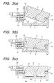
- the installation of the battery pack 3 on the battery mount 4 of the telephone body 2 is achieved by fitting the fixing recess 11, as shown in Fig. 3(a), to the fixing claw 10 and pressing, as shown in Fig. 3(b), the end of the battery pack 3 in which the fixing recess 6 is formed toward an upper surface of the battery mount 4, thereby forcing the slidable hook 20 into the hook chamber 15.
- the slidable hook 20 is, as shown in Fig. 3(c), moved outward by the spring pressure of the spring 14 to bring the central tapered portion 24 into constant engagement with the central recessed portion 22.
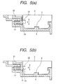
- a lower surface 24a of the central tapered portion 24 of the slidable hook 20, as clearly shown in Fig. 3(c), which is inclined upward about 45° to a sliding path of the slidable hook 20, is brought into engagement with a protrusion 22a of the battery pack 3 defining the central recessed portion 22 to split the spring pressure produced by the spring 14 into a horizontal pressure N, as shown in Fig. 4(b), and a downward pressure 0, as shown in Fig. 5(b).
- the horizontal pressure N urges the battery pack 3 in a lengthwise direction thereof to eliminate the gap, as shown in Fig.
- Each of the side tapered portions 23 of the slidable hook 20 is inserted into one of the side recessed portions 21 of the fixing recess 6, thereby holding the battery pack 3 from being dislodged from the battery mount 4 with engagement a flat surface 23a (i.e., the bottom of each side protrusion 23) with a flat surface 21a (i.e., the bottom of each side recessed portion 21) when the portable telephone 1 is twisted undesirably or when the battery pack 3 is pulled out of the battery mount 4 forcibly.
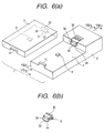
- Fig. 6(a) shows a battery holder structure for portable telephones according to the second embodiment of the invention which is different from the first embodiment in structure of a fixing recess 55 of a battery pack 3 and a slidable hook 30 installed in a telephone body 2.
- Other arrangements are identical, and explanation thereof in detail will be omitted here.
- the fixing recess 55 is formed in an end of the battery pack 3 and consists of a pair of side recessed portions 32 and a central recessed portion 31 extending downward from the side recessed portions 32.
- the slidable hook 3 is, similar to the first embodiment, spring-loaded within the hook chamber 15, as shown in Fig. 7(a), and includes, as clearly shown in Fig. 6(b), a wedge-shaped protrusion consisting of a pair of side tapered portions 34 and a central tapered portion 33 projecting forward and downward from the side tapered portions 34.
- the slidable hook 30 also includes a pair of barb-like protrusions 12 extending from the side tapered portions 34 backward.
- the barb-like protrusions 12 serve as stoppers which engage, as shown in Fig. 7(b), ribs 16 formed in the hook chamber 15 for holding the slidable hook 20 from being dislodged from the hook chamber 15 by the spring pressure of the spring 14.
- Each of the side tapered portions 34 has, as can be seen in Fig. 7(b), a lower tapered surface 34a which engages one of the corners of the bottoms of the side recessed portions 32 when the battery pack 3 is installed on the battery mount 4 to split the spring pressure produced by the spring 14 into a horizontal pressure N and a downward pressure O which are similar to the ones shown in Figs. 4(b) and 5(b).
- the horizontal pressure N urges the battery pack 3 in a lengthwise direction thereof to eliminate the gap between a side surface of the positioning protrusion 8 on the battery mount 4 and a side surface of the positioning recess 9 of the battery pack 3, thereby eliminating horizontal play of the battery pack 3.
- the downward pressure O urges the battery pack 3 in a thicknesswise direction thereof to eliminate the gap between the upper surface of the positioning protrusion 8 and the bottom surface of the positioning recess 9, thereby eliminating vertical play of the battery pack 3.
Landscapes
- Chemical & Material Sciences (AREA)
- Chemical Kinetics & Catalysis (AREA)
- Electrochemistry (AREA)
- General Chemical & Material Sciences (AREA)
- Engineering & Computer Science (AREA)
- Signal Processing (AREA)
- Battery Mounting, Suspending (AREA)
- Telephone Set Structure (AREA)
Claims (9)
- Dispositif de maintien pour maintenir un bloc de batterie (3) sur une monture de batterie (4), le dispositif comprenant :un élément de maintien (10) fourni sur une première partie d'extrémité de la monture de batterie pour maintenir une première partie d'extrémité du bloc de batterie sur la monture de batterie ; etun ensemble de crochet (20) fourni sur une deuxième partie d'extrémité de la monture de batterie (4) opposé à la première partie d'extrémité pour maintenir une deuxième partie d'extrémité du bloc de batterie (3) opposée à la première partie d'extrémité sur la monture de batterie, ledit ensemble de batterie (20) comprenant un ressort (14) et une protubérance (24) qui, en utilisation, est pressée au moyen d'une pression de ressort produite par le ressort en engagement permanent avec un évidement formé dans la deuxième partie d'extrémité du bloc de batterie (3), la protubérance ayant une forme telle qu'elle divise la pression du ressort en une pression horizontale et une pression verticale, la pression horizontale pressant la deuxième partie d'extrémité du bloc de batterie (3) contre ledit élément de maintien pour éliminer tout jeu horizontal du bloc de batterie (3) sur la monture de batterie (4), la pression verticale pressant la deuxième partie d'extrémité du bloc de batterie contre la monture de batterie pour éliminer tout jeu vertical du bloc de batterie sur la monture de batterie.
- Dispositif de maintien selon la revendication 1, dans lequel ledit ensemble de crochet (20) est à ressort au moyen du ressort (14) dans une chambre formée dans la monture de batterie (4) pour qu'ainsi la protubérance (24) dudit ensemble de crochet glisse dans la chambre lorsque le bloc de batterie (3) est adapté sur la monture de batterie (4) pour faciliter le montage du bloc de batterie sur la monture de batterie (4).
- Dispositif de maintien selon la revendication 1 ou 2, dans lequel la protubérance (24) dudit ensemble de crochet (20) a une surface inclinée selon un angle donné par rapport à une direction dans laquelle la pression du ressort, en utilisation, presse ledit ensemble de crochet dans un engagement constant de la protubérance avec l'évidement formé dans la deuxième partie d'extrémité du bloc de batterie de façon à diviser la pression du ressort en la pression horizontale et en la pression verticale.
- Dispositif de maintien selon la revendication 3, dans lequel la surface inclinée de ladite protubérance engage, en utilisation, un coin qui définit l'évidement du bloc de batterie (3) pour distribuer la pression du ressort dans une direction horizontale et dans une direction verticale pour produire la pression horizontale et la pression verticale.
- Dispositif de maintien selon la revendication 1, 2, 3 ou 4, dans lequel ledit ensemble de crochet (20) a aussi une paire de protubérances latérales (23) à travers ladite protubérance qui, en utilisation, sont insérées dans une paire de parties d'évidements latéraux formés à travers l'évidement formé dans la deuxième partie d'extrémité du bloc de batterie pour empêcher le délogement du bloc de batterie de la monture de batterie.
- Dispositif de maintien selon l'une quelconque des revendications 1 à 5, dans lequel ledit ensemble de crochet (20) comprend aussi une deuxième protubérance qui, en utilisation, est insérée dans une deuxième partie d'évidement formée dans la deuxième partie d'extrémité du bloc de batterie pour empêcher le délogement du bloc de batterie (3) de la monture de batterie (4).
- Dispositif de maintien selon la revendication 6, dans lequel ledit ensemble de crochet (20) comprend une troisième protubérance qui, en utilisation, est pressée au moyen de la pression du ressort dans un engagement permanent avec un troisième évidement formé dans la deuxième partie d'extrémité du bloc de batterie (3), la troisième protubérance ayant une surface inclinée selon un angle donné par rapport à la direction dans laquelle la pression du ressort presse ledit ensemble de crochet (20) dans un engagement permanent de la troisième protubérance avec le troisième évidement de façon à diviser la pression du ressort en une pression horizontale et en une pression verticale, la pression horizontale pressant la deuxième partie d'extrémité du bloc de batterie (3) contre ledit élément de maintien pour éliminer le jeu horizontal du bloc de batterie sur la monture de batterie (4), la pression verticale pressant la deuxième partie d'extrémité du bloc de batterie contre la monture de batterie pour éliminer le jeux vertical du bloc de batterie sur la monture de batterie.
- Dispositif de maintien selon la revendication 7, dans lequel la troisième protubérance est fournie à l'opposé de ladite protubérance à travers la deuxième protubérance, la surface inclinée de la troisième protubérance, en utilisation, engageant un coin qui définit le troisième évidement du bloc de batterie pour distribuer la pression du ressort dans une direction horizontale et dans une direction verticale pour produire la pression horizontale et la pression verticale.
- Dispositif électronique, tel qu'un téléphone portable, comprenant un dispositif de maintien selon l'une quelconque des revendications précédentes.
Applications Claiming Priority (3)
| Application Number | Priority Date | Filing Date | Title |
|---|---|---|---|
| JP26858796 | 1996-10-09 | ||
| JP268587/96 | 1996-10-09 | ||
| JP8268587A JP3060291B2 (ja) | 1996-10-09 | 1996-10-09 | 電池パックの保持装置 |
Publications (3)
| Publication Number | Publication Date |
|---|---|
| EP0836311A2 EP0836311A2 (fr) | 1998-04-15 |
| EP0836311A3 EP0836311A3 (fr) | 2000-08-23 |
| EP0836311B1 true EP0836311B1 (fr) | 2005-04-20 |
Family
ID=17460610
Family Applications (1)
| Application Number | Title | Priority Date | Filing Date |
|---|---|---|---|
| EP97307941A Expired - Lifetime EP0836311B1 (fr) | 1996-10-09 | 1997-10-08 | Structure améliorée pour maintenir une batterie d'alimentation dans un appareil électronique |
Country Status (5)
| Country | Link |
|---|---|
| US (1) | US5903132A (fr) |
| EP (1) | EP0836311B1 (fr) |
| JP (1) | JP3060291B2 (fr) |
| CN (1) | CN1125556C (fr) |
| DE (1) | DE69733052T2 (fr) |
Families Citing this family (53)
| Publication number | Priority date | Publication date | Assignee | Title |
|---|---|---|---|---|
| US5871272A (en) | 1997-01-28 | 1999-02-16 | Streamlight, Incorporated | Flashlight with rotatable lamp head |
| JP3429681B2 (ja) | 1998-08-06 | 2003-07-22 | 松下電器産業株式会社 | 電池パック取り外し装置 |
| JP4110657B2 (ja) * | 1999-02-17 | 2008-07-02 | ソニー株式会社 | バッテリーパック、バッテリー装着装置、電力供給装置及び電子機器 |
| JP4110656B2 (ja) * | 1999-02-17 | 2008-07-02 | ソニー株式会社 | バッテリーパック、バッテリー装着装置、電力供給装置及び電子機器 |
| JP3490017B2 (ja) | 1999-03-18 | 2004-01-26 | 松下電器産業株式会社 | 無線端末装置 |
| US6359418B1 (en) * | 1999-06-18 | 2002-03-19 | Leupold & Stevens, Inc. | Replaceable battery module |
| EP1071147A1 (fr) * | 1999-07-19 | 2001-01-24 | Toshiba Battery Co., Ltd. | Bloc-batterie |
| USD432984S (en) * | 1999-08-11 | 2000-10-31 | Vector Products, Inc. | Jumpstarter docking station |
| US6350040B1 (en) * | 2000-05-05 | 2002-02-26 | Pelican Products, Inc. | Flashlight charger and rechargeable battery |
| US6633152B2 (en) | 2001-04-26 | 2003-10-14 | Streamlight, Inc. | Rechargeable flashlight and battery charger |
| JP2003249805A (ja) | 2002-02-25 | 2003-09-05 | Nec Corp | アンテナ実装構造とアンテナを有する情報端末 |
| US20040056641A1 (en) * | 2002-06-18 | 2004-03-25 | Kenneth Myers | Battery powered device including a battery terminal configured to receive an auxiliary power plug |
| KR100475455B1 (ko) * | 2002-10-26 | 2005-04-06 | 주식회사 아트랑 | 외장형 전지팩 |
| AU2003302675A1 (en) * | 2002-11-29 | 2004-06-23 | Unilever Plc | Beverage product with modified starch and nitrogen |
| KR100506314B1 (ko) * | 2003-01-09 | 2005-08-05 | 삼성전자주식회사 | 휴대 단말기의 배터리 충전기 |
| US7215084B1 (en) | 2003-02-11 | 2007-05-08 | Streamlight, Inc. | Power control arrangement, as for a flashlight |
| JP4631254B2 (ja) * | 2003-07-25 | 2011-02-16 | 株式会社ケンウッド | 電子機器のバッテリパック装着構造 |
| KR100531890B1 (ko) * | 2003-09-29 | 2005-11-29 | 엘지전자 주식회사 | 이동단말기 |
| US7166987B2 (en) * | 2003-10-10 | 2007-01-23 | R. F. Tech Co., Ltd | Portable charger for mobile phone |
| US20050084747A1 (en) * | 2003-10-17 | 2005-04-21 | Allen Aaron R. | Latching mechanism for electronic device and method of assembly |
| JP2005235536A (ja) * | 2004-02-19 | 2005-09-02 | Konica Minolta Photo Imaging Inc | 電池パック及び電子機器 |
| KR100834626B1 (ko) | 2004-05-06 | 2008-06-02 | 삼성전자주식회사 | 자기 거치 기능을 구비한 슬라이딩/스윙 타입 휴대 장치 |
| DE202004021593U1 (de) * | 2004-09-10 | 2009-04-30 | Robert Bosch Gmbh | Batteriepack und Elektrowerkzeug |
| KR20060034353A (ko) * | 2004-10-18 | 2006-04-24 | 삼성전자주식회사 | 배터리팩과 배터리 착탈장치 및 전자기기 |
| CN2777910Y (zh) * | 2005-01-28 | 2006-05-03 | 深圳富泰宏精密工业有限公司 | 电池盖卡锁结构 |
| KR100689520B1 (ko) * | 2005-03-04 | 2007-03-02 | 삼성전자주식회사 | 휴대용 단말기의 배터리 팩 장착 장치 |
| TWI255574B (en) * | 2005-04-28 | 2006-05-21 | Asustek Comp Inc | Battery-engaging module of portable electronic device |
| CN100438731C (zh) * | 2005-04-30 | 2008-11-26 | 华硕电脑股份有限公司 | 可携式电子设备电池的装设模组 |
| TWI353678B (en) * | 2005-11-18 | 2011-12-01 | Fih Hong Kong Ltd | Battery cover for a communication unit |
| KR100933424B1 (ko) * | 2005-11-23 | 2009-12-23 | 주식회사 엘지화학 | 노트북 컴퓨터에서의 전지팩 락커 구조 |
| JP4725317B2 (ja) * | 2005-12-26 | 2011-07-13 | ソニー株式会社 | 電子機器 |
| AU320073S (en) * | 2007-09-12 | 2008-06-30 | Dyson Technology Ltd | A battery charger |
| CN101728501B (zh) * | 2008-10-31 | 2012-05-23 | 鸿富锦精密工业(深圳)有限公司 | 电池盒 |
| JP5861643B2 (ja) | 2010-10-29 | 2016-02-16 | 日本電気株式会社 | 電池パックのロック構造及び電子機器 |
| DE102010063777A1 (de) * | 2010-12-21 | 2012-06-21 | Endress + Hauser Process Solutions Ag | Transportsicherung für eine Batterieeinheit |
| CN202050003U (zh) * | 2011-04-21 | 2011-11-23 | 旭丽电子(广州)有限公司 | 电池的自动抬起机构及电子装置 |
| US8944844B2 (en) * | 2013-01-18 | 2015-02-03 | Tyco Electronics Corporation | Connector mating assurance |
| US20150035479A1 (en) * | 2013-07-30 | 2015-02-05 | Elite Lifestyle Products L.P. | Battery charger |
| US10381856B2 (en) * | 2014-10-03 | 2019-08-13 | Robert Bosch Tool Corporation | Inductive charging holster for power tool |
| US9833064B2 (en) * | 2015-07-23 | 2017-12-05 | Gamber-Johnson Llc | Keyboard mounting assembly |
| US11493073B2 (en) | 2017-08-18 | 2022-11-08 | Harting Electric Gmbh & Co. Kg | Locking mechanism for a plug connector housing |
| DE102017130005B3 (de) | 2017-12-14 | 2019-06-06 | Harting Electric Gmbh & Co. Kg | Steckverbinder |
| DE102017118918A1 (de) * | 2017-08-18 | 2019-02-21 | Harting Electric Gmbh & Co. Kg | Druckknopfverriegelung für ein Steckverbindergehäuse |
| US10320100B2 (en) * | 2017-10-06 | 2019-06-11 | Te Connectivity Corporation | Card edge connector assembly |
| CA3065350C (fr) * | 2018-03-02 | 2023-07-04 | Ergotron, Inc. | Systeme d'alimentation pour postes de travail mobiles |
| KR102249488B1 (ko) | 2018-03-12 | 2021-05-06 | 주식회사 엘지화학 | 훅 구조가 적용된 에너지 저장 장치 및 이를 포함하는 에너지 저장 시스템 |
| CN110112337B (zh) * | 2019-04-08 | 2022-05-17 | 河南平高电气股份有限公司 | 电池箱支撑滚轮及使用该支撑滚轮的储能装置 |
| CN110071240B (zh) * | 2019-04-08 | 2022-04-22 | 河南平高电气股份有限公司 | 电池箱导向组件及使用该组件的储能装置 |
| CN110620358B (zh) * | 2019-09-25 | 2020-12-08 | 广东稳峰电力科技有限公司 | 一种配电工程用电缆桥架的安装结构及安装方法 |
| GB2588140A (en) * | 2019-10-09 | 2021-04-21 | Shanq Ching Shieh | Battery installation mechanism for electric vehicle |
| KR102948498B1 (ko) * | 2021-03-16 | 2026-04-03 | 현대자동차 주식회사 | 배터리 모듈의 조립 장치 및 조립 방법 |
| KR20230151173A (ko) * | 2022-04-25 | 2023-11-01 | 주식회사 엘지에너지솔루션 | 교체형 배터리 모듈 |
| US20250260114A1 (en) * | 2024-02-12 | 2025-08-14 | Lenovo (Singapore) Pte. Ltd. | Screwless engagement assembly |
Family Cites Families (10)
| Publication number | Priority date | Publication date | Assignee | Title |
|---|---|---|---|---|
| US5028083A (en) * | 1990-04-27 | 1991-07-02 | Motorola, Inc. | Latch assembly |
| WO1992022146A1 (fr) * | 1991-06-03 | 1992-12-10 | Motorola, Inc. | Dispositif d'enclenchement de boitier de piles pour recepteur radio portatif |
| JPH05266869A (ja) * | 1992-03-18 | 1993-10-15 | Fujitsu Ltd | 電池パック着脱構造 |
| JP2861637B2 (ja) * | 1992-06-10 | 1999-02-24 | 松下電器産業株式会社 | 電池パック固定装置 |
| US5620242A (en) * | 1993-04-19 | 1997-04-15 | Motorola, Inc. | Portable radio battery latch |
| JP2526500B2 (ja) * | 1993-07-23 | 1996-08-21 | 日本電気株式会社 | 携帯電話機 |
| JP2741842B2 (ja) * | 1994-10-25 | 1998-04-22 | インターナショナル・ビジネス・マシーンズ・コーポレイション | バッテリーの着脱機構 |
| JP2746211B2 (ja) * | 1995-06-12 | 1998-05-06 | 日本電気株式会社 | 携帯用電子機器 |
| JP2842308B2 (ja) * | 1995-06-30 | 1999-01-06 | 日本電気株式会社 | 電子機器のバッテリケース実装構造 |
| DE29607055U1 (de) * | 1996-04-18 | 1996-07-04 | VARTA Gerätebatterie GmbH, 30419 Hannover | Batteriegehäuse für tragbare Telefone |
-
1996
- 1996-10-09 JP JP8268587A patent/JP3060291B2/ja not_active Expired - Fee Related
-
1997
- 1997-10-08 US US08/947,346 patent/US5903132A/en not_active Expired - Lifetime
- 1997-10-08 DE DE69733052T patent/DE69733052T2/de not_active Expired - Lifetime
- 1997-10-08 EP EP97307941A patent/EP0836311B1/fr not_active Expired - Lifetime
- 1997-10-09 CN CN97120567A patent/CN1125556C/zh not_active Expired - Fee Related
Also Published As
| Publication number | Publication date |
|---|---|
| US5903132A (en) | 1999-05-11 |
| EP0836311A2 (fr) | 1998-04-15 |
| JP3060291B2 (ja) | 2000-07-10 |
| EP0836311A3 (fr) | 2000-08-23 |
| DE69733052T2 (de) | 2006-01-19 |
| JPH10117224A (ja) | 1998-05-06 |
| CN1183689A (zh) | 1998-06-03 |
| DE69733052D1 (de) | 2005-05-25 |
| CN1125556C (zh) | 2003-10-22 |
Similar Documents
| Publication | Publication Date | Title |
|---|---|---|
| US5903132A (en) | Battery pack holding structure providing force components for eliminating play of an electronic device in plural dimensions | |
| US4356599A (en) | Stackable flat cable clamp | |
| US5033709A (en) | Holding device | |
| US5288250A (en) | Connector | |
| US4718742A (en) | Battery fitting device usable for electronic appliance | |
| JPH11329550A (ja) | 2つのプラグのコネクタ部材とその雄雌部材及びコネクタ装置 | |
| US5443159A (en) | Tri-cassette carrier | |
| US5090836A (en) | Structure of a connecting joint of a case | |
| CA1171990A (fr) | Support mural de telephone | |
| JPH07245839A (ja) | プロテクタ | |
| US4491695A (en) | Mounting for a dial in a telephone set base | |
| US5573870A (en) | Quick change battery pack assembly | |
| US3982809A (en) | Cord adapter | |
| GB2115601A (en) | Battery case and receptacle | |
| US5601940A (en) | Battery holder | |
| KR100388753B1 (ko) | 이동통신 단말기와 배터리의 체결 구조 | |
| JP2538539Y2 (ja) | パネルユニット取付構造 | |
| JPH0327411A (ja) | パーソナルコンピュータ | |
| CN212867179U (zh) | 电脑钥匙存放装置及钥匙管理机 | |
| US20240218929A1 (en) | Seal for a port of an enclosure configured to permit a pre-connectorized cable to be inserted into and removed from the seal with a connector attached to the cable | |
| US5242061A (en) | Apparatus for positioning interface cards in a computer housing | |
| JPH073716Y2 (ja) | ハンガの取付構造 | |
| JP2562705Y2 (ja) | コードレステレホン用の収容装置 | |
| KR100511313B1 (ko) | 내장형 배터리를 구비한 이동단말기 | |
| JPH019336Y2 (fr) |
Legal Events
| Date | Code | Title | Description |
|---|---|---|---|
| PUAI | Public reference made under article 153(3) epc to a published international application that has entered the european phase |
Free format text: ORIGINAL CODE: 0009012 |
|
| 17P | Request for examination filed |
Effective date: 19971017 |
|
| AK | Designated contracting states |
Kind code of ref document: A2 Designated state(s): DE FR GB |
|
| AX | Request for extension of the european patent |
Free format text: AL;LT;LV;RO;SI |
|
| PUAL | Search report despatched |
Free format text: ORIGINAL CODE: 0009013 |
|
| AK | Designated contracting states |
Kind code of ref document: A3 Designated state(s): AT BE CH DE DK ES FI FR GB GR IE IT LI LU MC NL PT SE |
|
| AX | Request for extension of the european patent |
Free format text: AL;LT;LV;RO;SI |
|
| RIC1 | Information provided on ipc code assigned before grant |
Free format text: 7H 04M 1/72 A, 7H 01M 2/10 B, 7H 04M 1/02 B |
|
| AKX | Designation fees paid |
Free format text: DE FR GB |
|
| GRAP | Despatch of communication of intention to grant a patent |
Free format text: ORIGINAL CODE: EPIDOSNIGR1 |
|
| GRAS | Grant fee paid |
Free format text: ORIGINAL CODE: EPIDOSNIGR3 |
|
| GRAA | (expected) grant |
Free format text: ORIGINAL CODE: 0009210 |
|
| AK | Designated contracting states |
Kind code of ref document: B1 Designated state(s): DE FR GB |
|
| REG | Reference to a national code |
Ref country code: GB Ref legal event code: FG4D |
|
| REF | Corresponds to: |
Ref document number: 69733052 Country of ref document: DE Date of ref document: 20050525 Kind code of ref document: P |
|
| PLBE | No opposition filed within time limit |
Free format text: ORIGINAL CODE: 0009261 |
|
| STAA | Information on the status of an ep patent application or granted ep patent |
Free format text: STATUS: NO OPPOSITION FILED WITHIN TIME LIMIT |
|
| ET | Fr: translation filed | ||
| 26N | No opposition filed |
Effective date: 20060123 |
|
| PGFP | Annual fee paid to national office [announced via postgrant information from national office to epo] |
Ref country code: DE Payment date: 20101006 Year of fee payment: 14 |
|
| PGFP | Annual fee paid to national office [announced via postgrant information from national office to epo] |
Ref country code: GB Payment date: 20101006 Year of fee payment: 14 |
|
| PGFP | Annual fee paid to national office [announced via postgrant information from national office to epo] |
Ref country code: FR Payment date: 20111103 Year of fee payment: 15 |
|
| GBPC | Gb: european patent ceased through non-payment of renewal fee |
Effective date: 20121008 |
|
| REG | Reference to a national code |
Ref country code: FR Ref legal event code: ST Effective date: 20130628 |
|
| PG25 | Lapsed in a contracting state [announced via postgrant information from national office to epo] |
Ref country code: DE Free format text: LAPSE BECAUSE OF NON-PAYMENT OF DUE FEES Effective date: 20130501 Ref country code: GB Free format text: LAPSE BECAUSE OF NON-PAYMENT OF DUE FEES Effective date: 20121008 |
|
| REG | Reference to a national code |
Ref country code: DE Ref legal event code: R119 Ref document number: 69733052 Country of ref document: DE Effective date: 20130501 |
|
| PG25 | Lapsed in a contracting state [announced via postgrant information from national office to epo] |
Ref country code: FR Free format text: LAPSE BECAUSE OF NON-PAYMENT OF DUE FEES Effective date: 20121031 |