EP0836539B1 - Kombination platte-innere ausgussdüse mit einer sollbruchstelle - Google Patents
Kombination platte-innere ausgussdüse mit einer sollbruchstelle Download PDFInfo
- Publication number
- EP0836539B1 EP0836539B1 EP96924909A EP96924909A EP0836539B1 EP 0836539 B1 EP0836539 B1 EP 0836539B1 EP 96924909 A EP96924909 A EP 96924909A EP 96924909 A EP96924909 A EP 96924909A EP 0836539 B1 EP0836539 B1 EP 0836539B1
- Authority
- EP
- European Patent Office
- Prior art keywords
- plate
- internal nozzle
- central
- area
- nozzle assembly
- Prior art date
- Legal status (The legal status is an assumption and is not a legal conclusion. Google has not performed a legal analysis and makes no representation as to the accuracy of the status listed.)
- Expired - Lifetime
Links
- 239000002184 metal Substances 0.000 claims abstract description 26
- 230000002093 peripheral effect Effects 0.000 claims abstract description 18
- 229910000831 Steel Inorganic materials 0.000 description 17
- 239000010959 steel Substances 0.000 description 17
- 241000282461 Canis lupus Species 0.000 description 10
- 238000005266 casting Methods 0.000 description 6
- 238000009749 continuous casting Methods 0.000 description 4
- 241000543067 Adenia spinosa Species 0.000 description 2
- 235000006146 Dioscorea elephantipes Nutrition 0.000 description 2
- 230000003628 erosive effect Effects 0.000 description 2
- 239000007788 liquid Substances 0.000 description 2
- 239000011819 refractory material Substances 0.000 description 2
- 239000002893 slag Substances 0.000 description 2
- 230000000712 assembly Effects 0.000 description 1
- 238000000429 assembly Methods 0.000 description 1
- 230000015572 biosynthetic process Effects 0.000 description 1
- 239000011449 brick Substances 0.000 description 1
- 238000001816 cooling Methods 0.000 description 1
- 230000007935 neutral effect Effects 0.000 description 1
- 230000000750 progressive effect Effects 0.000 description 1
- 230000003313 weakening effect Effects 0.000 description 1
Images


Classifications
-
- B—PERFORMING OPERATIONS; TRANSPORTING
- B22—CASTING; POWDER METALLURGY
- B22D—CASTING OF METALS; CASTING OF OTHER SUBSTANCES BY THE SAME PROCESSES OR DEVICES
- B22D41/00—Casting melt-holding vessels, e.g. ladles, tundishes, cups or the like
- B22D41/50—Pouring-nozzles
-
- B—PERFORMING OPERATIONS; TRANSPORTING
- B22—CASTING; POWDER METALLURGY
- B22D—CASTING OF METALS; CASTING OF OTHER SUBSTANCES BY THE SAME PROCESSES OR DEVICES
- B22D41/00—Casting melt-holding vessels, e.g. ladles, tundishes, cups or the like
- B22D41/14—Closures
- B22D41/22—Closures sliding-gate type, i.e. having a fixed plate and a movable plate in sliding contact with each other for selective registry of their openings
- B22D41/28—Plates therefor
Definitions
- the invention relates to an internal plate-nozzle assembly for a distributor, said plate being intended to be applied against a support in which an orifice is provided (see: WO-A-92/05901).
- a drawer shutter In the continuous casting of steel a shutter is frequently used for control the flow of steel between a distributor and one or more molds continuous casting.
- a drawer shutter has at least one fixed refractory plate mounted under a support plate and at least one plate movable relative to the fixed plate. Each of these plates has at least one hole for the passage of steel.
- the upper plate is associated with an internal nozzle which crosses the plate support and the bottom of the distributor.
- the rod of solidified steel which forms inside the runner up to the movable plate has, at its lower end, the shape of an elephant's foot which anchors the wolf in the fixed plate of the drawer shutter.
- each line leads to the formation of a wolf anchor in the dispatcher.
- the internal nozzle must be or pushed inside the dispatcher with the wolf. This problem is made worse in the case where there are several casting lines. In fact, steel contracts by cooling, so that the solidified steel rods tend to approach the each other. As these rods are embedded in the wall of the distributor they enclose the part of the distributor which is between them.
- the fixed plate and the internal nozzle are often assembled in an envelope metal which seals the nozzle when a neutral gas is injected into the runner and facilitates their handling during assembly.
- This metal casing reinforces the assembly of the plate and the internal nozzle. It is very difficult to destroy the fixed plate and the internal nozzle when pushing the wolf inward of the distributor because it requires extruding the metal casing through the hole provided in the support on which the fixed plate is applied.
- the present invention specifically relates to an internal plate / nozzle assembly which solves this problem.
- the plate / nozzle assembly comprises a central zone located opposite the orifice of the support and a peripheral zone applied to the support, the central zone and the peripheral zone being connected by a zone of least resistance so that the central area can be separated from the peripheral area by applying little effort.
- a metal envelope surrounds the area central and the peripheral zone, and the envelope comprises a weakened zone, in particular punched or notched.
- the envelope is made up of two parts separated, namely a part partially surrounding the peripheral zone and a part partially surrounding the central area.
- a metal envelope partially surrounds the internal nozzle, and a strapping band circles the plate.
- the internal nozzle has an external wall cylindrical or slightly flared, this wall being surrounded by an envelope metallic.
- the plate includes an insert located in the part center of the plate and whose outside diameter is smaller than the orifice provided in the support plate.
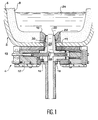
- FIG. 1 a sectional view of a continuous casting distributor designated by the reference 2 under which a valve shutter 4 is mounted.
- the distributor 2 consists of a steel wall 6 covered with a refractory lining 8.
- a seat brick 10 is mounted in the covering 8 at the bottom of the distributor.
- the shutter with drawer 4 has a frame 12 fixed under a support plate 13 mounted under the distributor.
- Three refractory plates are mounted in the frame 12, namely an upper plate fixed 14, a movable plate 16, and a fixed lower plate 18.
- An internal nozzle 20 is mounted with the fixed upper plate 14 in an envelope metal 22.
- the internal nozzle 20, the plates 14, 16 and 18 have holes which form a flow channel which allows the passage of steel from the distributor to a continuous casting mold (not shown).
- a continuous casting mold (not shown).
- we close the drawer by shifting the movable plate 16 relative to the fixed plate 14 so as to interrupt the continuity of the channel of casting.
- the liquid steel begins to cool and solidify, particularly in the channel of the internal nozzle 20 due to the low diameter of this channel.
- a solidified steel rod is formed which anchors the wolf 24 in the distributor 2.
- the lower end of the solidified steel rod 26 Due to the erosion of the internal nozzle 20 during casting the lower end of the solidified steel rod 26 has a flared shape 28 in shape of an elephant's foot which increases the grip of the wolf. This is why, when we turn the distributor 2 to extract the wolf, it does not fall but remains hung by the rod (s) 26. It is then necessary, after removing the drawer, which leaves the support plate and the internal plate / nozzle assembly on the distributor to exert a very great pressure on the steel rod 26 so as to break the fixed plate 14 and the internal nozzle 20 and to extrude the metal casing 22 through of the hole 30 provided in the support plate 13.
- the object of the invention is to provide an internal plate / nozzle assembly which facilitates the unbundling operation.
- the plate 14 / nozzle assembly internal 20 has a central zone located opposite the orifice 30 of the plate support 13 and a peripheral zone applied to the support plate 13.
- the zone central and the peripheral zone are connected to each other by a zone of least resistance.
- the envelope metal 22 has a circular cut 32 at the junction between the fixed plate 14 and internal nozzle 20.
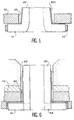
- This notch can be made in the part substantially vertical of the metal casing 22 as shown in FIG. 2, or on the horizontal part of this envelope, in the immediate vicinity of the connection of these two parts. Thanks to the presence of this notch the envelope metallic 22 tears easily when a relatively low force is applied to the steel rod 26.
- the central part of the metal casing 22 enters the distributor.
- the peripheral part remains outside on the fixed plate.
- the plate 14 / internal nozzle 20 assembly is produced in two assembled parts, these two parts separate.
- the refractory material breaks relatively easily. The presence of the notch 32 thus greatly facilitates the unbundling.
- FIGS. 2a and 2b show two alternative embodiments of the notch 32.
- the metal envelope 22 is notched on either side of its surface in the vertical part which surrounds the internal nozzle.
- the envelope metal 22 is notched at the horizontal surface which surrounds the fixed plate 14.
- FIG. 3 shows an alternative embodiment of the assemblies shown on Figures 1 and 2.
- the metal casing 22 is stamped with level of the junction between its horizontal part and its substantially vertical part of so as to constitute a weakening 36.
- FIG. 4 shows another embodiment of the invention.
- the envelope metal 22 consists of a part 22a which surrounds the internal nozzle 20 and a part 22b which envelops the fixed plate 14. These two parts can separate without effort. To perform the splitting operation, simply separate the internal nozzle from plate 14 (together in two parts) or break the refractory material (together monobloc) which requires little effort.
- Part 22b of the envelope metal 22 has a vertical rim 38. Part 22a of the metal casing is supported on the outside of this vertical rim 38 (FIG. 4a) or on the inside of the rim 38 ( Figure 4b).
- FIG. 5 shows a third embodiment of the invention.
- the metallic envelope consists of a single part 22c which surrounds only the internal nozzle 20.
- the fixed plate 14 is not surrounded by a metal envelope, but simply by a strapping 40. Because the metal casing 22c and the strapping 40 are independent and separate, it is easy to pass the central area of the plate / internal nozzle assembly through the hole 30 provided in the plate 13, exactly in the same way as in the case of the embodiment of FIG. 4.
- FIG. 6 shows a third embodiment of the invention.
- Wall outside of the nozzle 20 is cylindrical so that the part of the envelope metal 22 which is applied against this outer wall is vertical and of section constant.
- the fixed plate 14 has, in its central part, an insert 42.
- the outside diameter of the insert 42 is smaller than the diameter of the hole 30 provided in the support plate 13. In this way the internal nozzle 20 and the insert 42 can be easily pushed inside the distributor by sliding on the casing metal 22.
- the outer part of the fixed plate 14 and the metal casing 22 remain attached to the drawer shutter and the distributor.
Landscapes
- Engineering & Computer Science (AREA)
- Mechanical Engineering (AREA)
- Casting Support Devices, Ladles, And Melt Control Thereby (AREA)
- Closures For Containers (AREA)
- Nozzles (AREA)
- Turbine Rotor Nozzle Sealing (AREA)
- Cartons (AREA)
- Tubes (AREA)
- Paper (AREA)
- Particle Formation And Scattering Control In Inkjet Printers (AREA)
- Filling Or Discharging Of Gas Storage Vessels (AREA)
- Containers And Packaging Bodies Having A Special Means To Remove Contents (AREA)
Claims (6)
- Einheit aus Platte und innerem Ausguss für einen Verteiler, wobei die besagte Platte (14) dazu vorgesehen ist, gegen eine Abstützung (13) angelegt zu werden, in der eine Öffnung (30) vorgesehen ist, dadurch gekennzeichnet, dass sie eine gegenüber von der Öffnung (30) gelegene Mittenzone und eine auf der Abstützung (13) anliegende Randzone aufweist, wobei die Mittenzone und die Randzone durch eine Zone geringerer Festigkeit (32) verbunden sind, so dass die Mittenzone durch Aufbringen einer nicht sehr großen Kraft von der Randzone getrennt werden kann.
- Einheit aus Platte und innerem Ausguss nach Anspruch 1, bei der eine metallische Umhüllung (22) die Mittenzone und die Randzone teilweise umgibt, dadurch gekennzeichnet, dass die Umhüllung (22) eine Schwächungszone (32) aufweist, die insbesondere perforiert oder eingekerbt ist.
- Einheit aus Platte und innerem Ausguss nach Anspruch 1, bei der eine metallische Umhüllung (22) die Mittenzone und die Randzone teilweise umgibt, dadurch gekennzeichnet, dass die besagte Umhüllung (22) von zwei getrennten Teilen gebildet wird, nämlich einem Teil (22b), das die Randzone teilweise umgibt, und einem Teil (22a), das die Mittenzone teilweise umgibt.
- Einheit aus Platte und innerem Ausguss nach Anspruch 1, dadurch gekennzeichnet, dass sie eine metallische Umhüllung (22) aufweist, die den inneren Ausguss (20) teilweise umgibt, sowie ein Umreifungsband (40), das die Mittenzone teilweise umschlingt.
- Einheit aus Platte und innerem Ausguss nach einem der Ansprüche 1 bis 4, dadurch gekennzeichnet, dass der innere Ausguss (20) eine zylindrische oder leicht konisch erweiterte Außenwand aufweist, wobei diese Außenwand von einer metallischen Umhüllung (22) umgeben ist.
- Einheit aus Platte und innerem Ausguss nach einem der Ansprüche 1 bis 5, dadurch gekennzeichnet, dass die Platte (14) einen Einsatz (42) aufweist, der sich im mittleren Teil der Platte (14) befindet und dessen Außendurchmesser kleiner als die in der Abstützplatte (13) vorgesehene Öffnung (30) ist.
Applications Claiming Priority (3)
| Application Number | Priority Date | Filing Date | Title |
|---|---|---|---|
| FR9508088A FR2736289B1 (fr) | 1995-07-03 | 1995-07-03 | Ensemble plaque-busette interne comportant une zone de moindre resistance |
| FR9508088 | 1995-07-03 | ||
| PCT/FR1996/001017 WO1997002104A1 (fr) | 1995-07-03 | 1996-06-28 | Ensemble plaque-busette interne comportant une zone de moindre resistance |
Publications (2)
| Publication Number | Publication Date |
|---|---|
| EP0836539A1 EP0836539A1 (de) | 1998-04-22 |
| EP0836539B1 true EP0836539B1 (de) | 1999-08-25 |
Family
ID=9480690
Family Applications (1)
| Application Number | Title | Priority Date | Filing Date |
|---|---|---|---|
| EP96924909A Expired - Lifetime EP0836539B1 (de) | 1995-07-03 | 1996-06-28 | Kombination platte-innere ausgussdüse mit einer sollbruchstelle |
Country Status (12)
| Country | Link |
|---|---|
| US (1) | US6082599A (de) |
| EP (1) | EP0836539B1 (de) |
| KR (1) | KR100427608B1 (de) |
| CN (1) | CN1072080C (de) |
| AT (1) | ATE183680T1 (de) |
| AU (1) | AU6521096A (de) |
| DE (1) | DE69603964T2 (de) |
| ES (1) | ES2138361T3 (de) |
| FR (1) | FR2736289B1 (de) |
| TW (1) | TW298570B (de) |
| WO (1) | WO1997002104A1 (de) |
| ZA (1) | ZA965600B (de) |
Families Citing this family (3)
| Publication number | Priority date | Publication date | Assignee | Title |
|---|---|---|---|---|
| JP4159075B2 (ja) * | 2001-05-23 | 2008-10-01 | 黒崎播磨株式会社 | スライドゲートプレート |
| ES2364737T3 (es) | 2009-07-01 | 2011-09-13 | REFRACTORY INTELLECTUAL PROPERTY GMBH & CO. KG | Boquilla de colada. |
| CN114042903A (zh) * | 2021-11-18 | 2022-02-15 | 一重集团大连工程技术有限公司 | 三滑板滑动水口 |
Family Cites Families (10)
| Publication number | Priority date | Publication date | Assignee | Title |
|---|---|---|---|---|
| DE1938117C2 (de) * | 1969-07-26 | 1975-12-18 | Didier Werke Ag | Behälter mit Schieberverschluß für flüssige Schmelze |
| DE2548854A1 (de) * | 1975-10-31 | 1977-05-05 | Metacon Ag | Feuerfester stein mit einer durchlassoeffnung fuer fluessiges metall und verfahren zu dessen herstellung |
| DE3304938C1 (de) * | 1983-02-12 | 1984-05-03 | Didier-Werke Ag, 6200 Wiesbaden | Verfahren zum Aufbringen eines metallischen Spannbandes auf die Umfangsflaeche einer Verschlussplatte fuer einen Schiebeverschluss |
| DE3512907C2 (de) * | 1985-04-11 | 1991-01-03 | Stopinc Ag, Baar | Ausgusshülse für einen Metalschmelze enthaltenden Behälter |
| JP2667830B2 (ja) * | 1987-09-07 | 1997-10-27 | 株式会社クラレ | エチレン−ビニルアルコール系共重合体組成物 |
| FR2643001A1 (fr) * | 1989-01-05 | 1990-08-17 | Vesuvius Sa | Organe de coulee comportant une surface plane de glissement pour une plaque tiroir associee |
| US5188743A (en) * | 1989-03-03 | 1993-02-23 | Flo-Con Systems, Inc. | Plate, changer, plate and method |
| US5044533A (en) * | 1990-10-01 | 1991-09-03 | Flo-Con Systems, Inc. | Clamp for bandless refractory and method |
| FI91371C (fi) * | 1992-09-04 | 1994-06-27 | Indref Oy | Valusenkan suutiili sekä menetelmät sen valmistamiseksi ja uudistamiseksi |
| US5431374A (en) * | 1993-10-29 | 1995-07-11 | Vesuvius Crucible Company | Nozzle and base plate apparatus and method for use in a tundish slide gate valve |
-
1995
- 1995-07-03 FR FR9508088A patent/FR2736289B1/fr not_active Expired - Fee Related
-
1996
- 1996-06-28 WO PCT/FR1996/001017 patent/WO1997002104A1/fr not_active Ceased
- 1996-06-28 EP EP96924909A patent/EP0836539B1/de not_active Expired - Lifetime
- 1996-06-28 US US08/973,107 patent/US6082599A/en not_active Expired - Fee Related
- 1996-06-28 CN CN96195215A patent/CN1072080C/zh not_active Expired - Fee Related
- 1996-06-28 ES ES96924909T patent/ES2138361T3/es not_active Expired - Lifetime
- 1996-06-28 KR KR1019970709494A patent/KR100427608B1/ko not_active Expired - Fee Related
- 1996-06-28 AU AU65210/96A patent/AU6521096A/en not_active Abandoned
- 1996-06-28 DE DE69603964T patent/DE69603964T2/de not_active Expired - Fee Related
- 1996-06-28 AT AT96924909T patent/ATE183680T1/de not_active IP Right Cessation
- 1996-07-02 ZA ZA965600A patent/ZA965600B/xx unknown
- 1996-07-15 TW TW085107980A patent/TW298570B/zh active
Also Published As
| Publication number | Publication date |
|---|---|
| EP0836539A1 (de) | 1998-04-22 |
| DE69603964T2 (de) | 1999-12-09 |
| KR19990023024A (ko) | 1999-03-25 |
| ES2138361T3 (es) | 2000-01-01 |
| US6082599A (en) | 2000-07-04 |
| FR2736289A1 (fr) | 1997-01-10 |
| ZA965600B (en) | 1997-01-27 |
| ATE183680T1 (de) | 1999-09-15 |
| CN1189791A (zh) | 1998-08-05 |
| WO1997002104A1 (fr) | 1997-01-23 |
| TW298570B (de) | 1997-02-21 |
| AU6521096A (en) | 1997-02-05 |
| MX9710455A (es) | 1998-03-31 |
| CN1072080C (zh) | 2001-10-03 |
| FR2736289B1 (fr) | 1997-08-29 |
| KR100427608B1 (ko) | 2004-09-08 |
| DE69603964D1 (de) | 1999-09-30 |
Similar Documents
| Publication | Publication Date | Title |
|---|---|---|
| FR2529811A1 (fr) | Fermeture pour un recipient renfermant une masse metallique fondue liquide, notamment fermeture a tiroir pour poche de coulee | |
| FR2524919A1 (fr) | Dispositif d'encastrement de chevilles de fixation dans des panneaux composites | |
| EP1099529B1 (de) | Verfahren zur Herstellung von Behältern mit einem Behältermündungseinsatz durch Blasformen | |
| FR2966172A1 (fr) | Procede et dispositif pour la soudure aluminothermique de rails | |
| EP0387155B1 (de) | Meatuspfropf für Lakrimalpathologie | |
| CA2607923C (fr) | Dispositif de bouchage d'un col de recipient, recipient equipe d'un tel dispositif, procede de bouchage d'un tel recipient et procede de fabrication d'un tel dispositif | |
| EP0836539A1 (de) | Kombination platte-innere ausgussdüse mit einer sollbruchstelle | |
| FR2569591A1 (fr) | Plaque refractaire pour obturateurs coulissants de recipients metallurgiques | |
| FR2767082A1 (fr) | Busette de coulee pour le transfert d'un metal liquide d'un repartiteur dans une lingotiere | |
| FR2523006A1 (fr) | Filiere tubulaire pour la coulee continue d'un tube, a paroi mince, en fonte | |
| FR2701248A1 (fr) | Dispositif de bouchage pour récipient, son procédé de fabrication et récipient équipé d'un tel dispositif. | |
| FR2471416A1 (fr) | Elements refractaires poreux et procede de fabrication | |
| FR2530744A1 (fr) | Reservoir de pression tel qu'accumulateur de pression et son procede de fabrication | |
| EP1028822B1 (de) | Auslassrohr einer giesspfanne | |
| FR2596487A1 (fr) | Procede de realisation d'un composant de robinetterie et composant de robinetterie obtenu par la mise en oeuvre dudit procede | |
| FR2521462A1 (fr) | Dispositif d'amenee du metal dans les lingotieres de coulee continue | |
| FR2656042A1 (fr) | Procede de realisation de puits de bougie dans une culasse d'un moteur a combustion interne et element de puits de bougie destine a etre utilise pour la mise en óoeuvre de ce procede. | |
| EP0341179B1 (de) | Gussstück versehen mit einem zerstörbaren Teil | |
| FR2553317A1 (fr) | Joint pour installation de coulee continue horizontale des metaux notamment de l'acier et installation de coulee equipee de ce joint | |
| EP1095672B1 (de) | Brandschützende Ventilationsöffnung | |
| FR2610514A1 (fr) | Prothese d'articulation avec une liaison ceramique et un autre materiau, ainsi que le procede de fabrication d'une telle prothese | |
| BE1006006A3 (fr) | Piece refractaire pour trou de coulee d'un recipient siderurgique. | |
| FR2541915A2 (fr) | Dispositif d'amenee du metal dans les lingotieres de coulee continue | |
| WO2003071033A1 (fr) | Gaine d'ancrage permettant l'assemblage d'un organe fonctionnel a un substrat | |
| FR2800655A1 (fr) | Procede d'alimentation pour le moulage d'une piece avec insert |
Legal Events
| Date | Code | Title | Description |
|---|---|---|---|
| PUAI | Public reference made under article 153(3) epc to a published international application that has entered the european phase |
Free format text: ORIGINAL CODE: 0009012 |
|
| 17P | Request for examination filed |
Effective date: 19971219 |
|
| AK | Designated contracting states |
Kind code of ref document: A1 Designated state(s): AT BE DE ES FR GB IT LU NL SE |
|
| GRAG | Despatch of communication of intention to grant |
Free format text: ORIGINAL CODE: EPIDOS AGRA |
|
| 17Q | First examination report despatched |
Effective date: 19980821 |
|
| GRAG | Despatch of communication of intention to grant |
Free format text: ORIGINAL CODE: EPIDOS AGRA |
|
| GRAH | Despatch of communication of intention to grant a patent |
Free format text: ORIGINAL CODE: EPIDOS IGRA |
|
| GRAH | Despatch of communication of intention to grant a patent |
Free format text: ORIGINAL CODE: EPIDOS IGRA |
|
| GRAA | (expected) grant |
Free format text: ORIGINAL CODE: 0009210 |
|
| AK | Designated contracting states |
Kind code of ref document: B1 Designated state(s): AT BE DE ES FR GB IT LU NL SE |
|
| REF | Corresponds to: |
Ref document number: 183680 Country of ref document: AT Date of ref document: 19990915 Kind code of ref document: T |
|
| RIN1 | Information on inventor provided before grant (corrected) |
Inventor name: RICHARD, FRANCOIS-NOEL |
|
| ITF | It: translation for a ep patent filed | ||
| GBT | Gb: translation of ep patent filed (gb section 77(6)(a)/1977) |
Effective date: 19990827 |
|
| REF | Corresponds to: |
Ref document number: 69603964 Country of ref document: DE Date of ref document: 19990930 |
|
| REG | Reference to a national code |
Ref country code: ES Ref legal event code: FG2A Ref document number: 2138361 Country of ref document: ES Kind code of ref document: T3 |
|
| PLBE | No opposition filed within time limit |
Free format text: ORIGINAL CODE: 0009261 |
|
| STAA | Information on the status of an ep patent application or granted ep patent |
Free format text: STATUS: NO OPPOSITION FILED WITHIN TIME LIMIT |
|
| 26N | No opposition filed | ||
| REG | Reference to a national code |
Ref country code: GB Ref legal event code: IF02 |
|
| PGFP | Annual fee paid to national office [announced via postgrant information from national office to epo] |
Ref country code: SE Payment date: 20030619 Year of fee payment: 8 Ref country code: FR Payment date: 20030619 Year of fee payment: 8 |
|
| PGFP | Annual fee paid to national office [announced via postgrant information from national office to epo] |
Ref country code: GB Payment date: 20030625 Year of fee payment: 8 |
|
| PGFP | Annual fee paid to national office [announced via postgrant information from national office to epo] |
Ref country code: DE Payment date: 20030630 Year of fee payment: 8 |
|
| PGFP | Annual fee paid to national office [announced via postgrant information from national office to epo] |
Ref country code: LU Payment date: 20030703 Year of fee payment: 8 |
|
| PGFP | Annual fee paid to national office [announced via postgrant information from national office to epo] |
Ref country code: ES Payment date: 20030708 Year of fee payment: 8 |
|
| PGFP | Annual fee paid to national office [announced via postgrant information from national office to epo] |
Ref country code: BE Payment date: 20030724 Year of fee payment: 8 |
|
| PGFP | Annual fee paid to national office [announced via postgrant information from national office to epo] |
Ref country code: NL Payment date: 20040528 Year of fee payment: 9 |
|
| PGFP | Annual fee paid to national office [announced via postgrant information from national office to epo] |
Ref country code: AT Payment date: 20040603 Year of fee payment: 9 |
|
| PG25 | Lapsed in a contracting state [announced via postgrant information from national office to epo] |
Ref country code: LU Free format text: LAPSE BECAUSE OF NON-PAYMENT OF DUE FEES Effective date: 20040628 Ref country code: GB Free format text: LAPSE BECAUSE OF NON-PAYMENT OF DUE FEES Effective date: 20040628 |
|
| PG25 | Lapsed in a contracting state [announced via postgrant information from national office to epo] |
Ref country code: SE Free format text: LAPSE BECAUSE OF NON-PAYMENT OF DUE FEES Effective date: 20040629 Ref country code: ES Free format text: LAPSE BECAUSE OF NON-PAYMENT OF DUE FEES Effective date: 20040629 |
|
| PG25 | Lapsed in a contracting state [announced via postgrant information from national office to epo] |
Ref country code: BE Free format text: LAPSE BECAUSE OF NON-PAYMENT OF DUE FEES Effective date: 20040630 |
|
| BERE | Be: lapsed |
Owner name: S.A. *VESUVIUS FRANCE Effective date: 20040630 |
|
| PG25 | Lapsed in a contracting state [announced via postgrant information from national office to epo] |
Ref country code: DE Free format text: LAPSE BECAUSE OF NON-PAYMENT OF DUE FEES Effective date: 20050101 |
|
| EUG | Se: european patent has lapsed | ||
| EUG | Se: european patent has lapsed | ||
| GBPC | Gb: european patent ceased through non-payment of renewal fee |
Effective date: 20040628 |
|
| PG25 | Lapsed in a contracting state [announced via postgrant information from national office to epo] |
Ref country code: FR Free format text: LAPSE BECAUSE OF NON-PAYMENT OF DUE FEES Effective date: 20050228 |
|
| REG | Reference to a national code |
Ref country code: FR Ref legal event code: ST |
|
| PG25 | Lapsed in a contracting state [announced via postgrant information from national office to epo] |
Ref country code: IT Free format text: LAPSE BECAUSE OF NON-PAYMENT OF DUE FEES Effective date: 20050628 Ref country code: AT Free format text: LAPSE BECAUSE OF NON-PAYMENT OF DUE FEES Effective date: 20050628 |
|
| REG | Reference to a national code |
Ref country code: ES Ref legal event code: FD2A Effective date: 20040629 |
|
| PG25 | Lapsed in a contracting state [announced via postgrant information from national office to epo] |
Ref country code: NL Free format text: LAPSE BECAUSE OF NON-PAYMENT OF DUE FEES Effective date: 20060101 |
|
| NLV4 | Nl: lapsed or anulled due to non-payment of the annual fee |
Effective date: 20060101 |