EP0836694B1 - Fortbewegbarer roboter zur internen kontrolle von rohrleitungen - Google Patents
Fortbewegbarer roboter zur internen kontrolle von rohrleitungen Download PDFInfo
- Publication number
- EP0836694B1 EP0836694B1 EP96921920A EP96921920A EP0836694B1 EP 0836694 B1 EP0836694 B1 EP 0836694B1 EP 96921920 A EP96921920 A EP 96921920A EP 96921920 A EP96921920 A EP 96921920A EP 0836694 B1 EP0836694 B1 EP 0836694B1
- Authority
- EP
- European Patent Office
- Prior art keywords
- unit
- movable
- carrier unit
- robot
- pipe
- Prior art date
- Legal status (The legal status is an assumption and is not a legal conclusion. Google has not performed a legal analysis and makes no representation as to the accuracy of the status listed.)
- Expired - Lifetime
Links
- 238000007689 inspection Methods 0.000 title description 3
- 230000000063 preceeding effect Effects 0.000 claims 1
- 238000012544 monitoring process Methods 0.000 description 8
- 210000001364 upper extremity Anatomy 0.000 description 4
- XAGFODPZIPBFFR-UHFFFAOYSA-N aluminium Chemical compound [Al] XAGFODPZIPBFFR-UHFFFAOYSA-N 0.000 description 3
- 229910052782 aluminium Inorganic materials 0.000 description 3
- 239000004411 aluminium Substances 0.000 description 3
- 238000004891 communication Methods 0.000 description 3
- 230000007547 defect Effects 0.000 description 2
- 238000003780 insertion Methods 0.000 description 2
- 230000037431 insertion Effects 0.000 description 2
- 229910000831 Steel Inorganic materials 0.000 description 1
- 239000004020 conductor Substances 0.000 description 1
- 238000010276 construction Methods 0.000 description 1
- 230000008602 contraction Effects 0.000 description 1
- 125000004122 cyclic group Chemical group 0.000 description 1
- 238000009434 installation Methods 0.000 description 1
- 230000007257 malfunction Effects 0.000 description 1
- 238000004088 simulation Methods 0.000 description 1
- 239000010959 steel Substances 0.000 description 1
- 230000001360 synchronised effect Effects 0.000 description 1
- 238000011179 visual inspection Methods 0.000 description 1
Images


Classifications
-
- F—MECHANICAL ENGINEERING; LIGHTING; HEATING; WEAPONS; BLASTING
- F16—ENGINEERING ELEMENTS AND UNITS; GENERAL MEASURES FOR PRODUCING AND MAINTAINING EFFECTIVE FUNCTIONING OF MACHINES OR INSTALLATIONS; THERMAL INSULATION IN GENERAL
- F16L—PIPES; JOINTS OR FITTINGS FOR PIPES; SUPPORTS FOR PIPES, CABLES OR PROTECTIVE TUBING; MEANS FOR THERMAL INSULATION IN GENERAL
- F16L55/00—Devices or appurtenances for use in, or in connection with, pipes or pipe systems
- F16L55/26—Pigs or moles, i.e. devices movable in a pipe or conduit with or without self-contained propulsion means
- F16L55/28—Constructional aspects
-
- B—PERFORMING OPERATIONS; TRANSPORTING
- B08—CLEANING
- B08B—CLEANING IN GENERAL; PREVENTION OF FOULING IN GENERAL
- B08B9/00—Cleaning hollow articles by methods or apparatus specially adapted thereto
- B08B9/02—Cleaning pipes or tubes or systems of pipes or tubes
- B08B9/027—Cleaning the internal surfaces; Removal of blockages
- B08B9/04—Cleaning the internal surfaces; Removal of blockages using cleaning devices introduced into and moved along the pipes
- B08B9/049—Cleaning the internal surfaces; Removal of blockages using cleaning devices introduced into and moved along the pipes having self-contained propelling means for moving the cleaning devices along the pipes, i.e. self-propelled
-
- F—MECHANICAL ENGINEERING; LIGHTING; HEATING; WEAPONS; BLASTING
- F16—ENGINEERING ELEMENTS AND UNITS; GENERAL MEASURES FOR PRODUCING AND MAINTAINING EFFECTIVE FUNCTIONING OF MACHINES OR INSTALLATIONS; THERMAL INSULATION IN GENERAL
- F16L—PIPES; JOINTS OR FITTINGS FOR PIPES; SUPPORTS FOR PIPES, CABLES OR PROTECTIVE TUBING; MEANS FOR THERMAL INSULATION IN GENERAL
- F16L2101/00—Uses or applications of pigs or moles
- F16L2101/30—Inspecting, measuring or testing
Definitions
- the invention relates to a movable robot comprising a carrier unit and a manipulator unit, the carrier unit causing an axial movement in a pipe line and comprising two or several intermovable units, each of said movable units preferably provided with three projecting arms having contact surfaces for abutting the inner surface of the pipe, such that movable units is fixed relative to the pipe.
- Norwegian published specification No. 155 232 discloses a self-propelled pipe pig comprising a stepping device in two pieces.
- This stepping device comprises a forward stepping element and a rear stepping element each provided with a device for clamping it to the inner surface of the pipe.
- One of these elements is further provided with drive means for axial movement of the forward stepping element unit relative to the rear stepping element.
- this pipe pig is not adapted to pass obstacles in form of pipe stubs in the pipe. Many pipe connections in nuclear power stations are encumbered with such obstacles reducing the inside diameter of the pipe.
- German patent No. 3 419 683 (corresponding to EP patent No. 0 170. 609) discloses a pipe pig for indicating defects on the inner side of a pipe.
- the pipe pig comprises two interdisplaced movable units. One of these units is provided with three projecting arms which may abut the inner surface of the pipe, pivotally arranged rollers being provided at the end of the arms. The arms may rotate around the longitudinal axis to allow the pipe pig to pass obstacles, if any, e.g. in form of stubs in the pipe, said obstacles being detected by means of a television camera.
- One drawback of this construction is that the movement of the complete unit depends on the friction created by a number of rollers (wheels) on the inner surface of the pipe.
- the friction is not provided, if essential parts of the inner pipe face are replaced by other components of a geometrical structure deviating from the structure of the original pipe face. This is often the case in complex pipe lines in nuclear power systems. For the same reason and also when the wheels abut the pipe wall, the wheels are not able to roll without slip. This reduces the possibility of establishing an accurate position.
- the object of the present invention is to provide a more flexible movable robot, whereby the accurate position is determined in a more simple manner than hitherto known.
- a robot of the above type according to the invention is characterised by a rotation connection and a prismatic connection interconnecting the two or several intermovable units the prismatic connection and the rotation connection being controlled by different means and by one of the movable units being fixed relative to the pipe, at least one of the other movable units being movable relative thereto, and the other movable unit being rotable as well as well as displaceable relative to the fixed unit acting as a fixed reference for the other unit.
- the exact position of the robot may be provided at any time, the position being continuously set relative to a fixed reference position.
- the fixed reference is not fixed in the usual sense, but is established by the presently stationary part of the two-part, movable robot.
- the accuracy is such that the travel pattern during insertion of the robot also may be used during retraction, as the travel pattern in this case is performed in the opposite sequence.
- the robot may be adapted such that each set of legs may be moved synchronously in and out of the carrier unit according to the "umbrella principle".
- a movable robot is provided for internal inspection of a pipe system.
- the following criteria are essential for the structure of the robot:
- tool manipulator unit having six axes.
- Such a tool manipulator unit is advantageous in many ways. Several tools may be mounted in such a unit, whereby it is possible to alternate between different tools without removing the robot from the pipe.
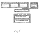
- the main components of the inspection system are shown in Fig. 1.
- the primary components are the carrier unit and the movable manipulator unit mounted thereon.
- the tools can be mounted on the manipulator unit.
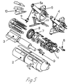
- the carrier unit is shown in Fig. 2.
- Various insertion units can be used for the installation/removal of the robot in a pipe system or the robot can be inserted manually.
- the robot is connected to an external control system comprising hardware and software for the simulation and monitoring of the robot.
- the system further comprises sensors and recording units for the control and monitoring of the robot. If desired, cameras for visual inspection of the pipe system can be mounted.
- the carrier unit is based on a traveller principle and provided with two sets of legs 4, 5.
- the legs 4,5 are arranged in separate parts of the carrier unit. The two parts are interconnected by a rotation and prismatic connection. This connection enables the carrier unit to move forward and backward in pipes and pipe lines and pass obstacles, if any, therein.
- Each set of legs comprises three legs.
- a circular friction pad 4a, 5a having a spring-loaded steel ball is provided at the end of each leg 4,5.
- Each set of legs 4,5 can be moved synchronously in and out according to the "umbrella principle" to ensure a centering of the carrier unit and a fixed contact between the friction pads 4a,5a and the pipe surface.
- the legs 4, 5, the rotation connection 8 and the prismatic connection 7 are all supplied with energy via double-acting pneumatic cylinders provided with coders enabling a positioning of the legs 4,5 and thus providing flexibility to compensate for variations in the diameter of the pipe.
- the pneumatic is reliable in relation to variations in the pipe diameter and able to withstand overloadings which might damage the carrier unit.
- Each of the legs are moreover provided with a sensor mechanism, e.g. in form of a pressure sensor. The sensor mechanism is able to register influences from all directions.
- the carrier unit is moved forwards and backwards in the pipe by extension/contraction of the front legs 5, the rear legs 4 and the prismatic connection in a special cyclic order, confer Fig. 3 illustrating this cycle.
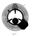
- the robot is to be able to pass obstacles in form of holes or objects in the pipe, confer Fig. 4.
- a rotation connection 8 is provided to enable the robot to pass obstacles 21 in the pipe.
- the legs can be adjusted relative to the obstacles 21 and pass these.
- the robot can pass closely spaced obstacles, as the carrier unit can rotate on the spot without moving backward or forwards in the pipe.
- the first set of legs rotates by retracting the legs such that the friction pads 4a or 5a no longer abut the pipe wall, the spring-loaded balls, however, still abutting the wall.
- the rotation connection 8 can also be used to maintain the carrier unit in a chosen orientation and thus compensate for external factors which otherwise may influence the orientation of the carrier unit.
- the control system for the pneumatic cylinders moving the legs is adapted such that in case a leg inadvertently is pushed into a hole in the pipe wall, only a portion corresponding to a diameter exceeding the pipe diameter at the position of the carrier unit by 10 mm is pushed into said hole. Thus, it is always possible to retract and rotate said leg.
- the friction pads 4a, 5a on the legs 4, 5 are further supported such that they can adjust to the inner face of the pipe when the carrier unit is moved in a pipe bend.
- This principle of the carrier unit is not only chosen, since it enables the carrier unit to move around in the pipes and pass obstacles 21, but also since only comparatively few and simple movable parts are required.
- the carrier unit is torpedo-shaped and has a diameter of approximately 330 mm.
- the legs can be completely retracted, thus providing the carrier unit with a smooth surface so as to reduce the risk of the carrier unit being caught on obstacles, if it is retracted in case of failures, such as power failure and/or defects in the control signals.
- the legs are spring-loaded such that they are automatically retracted into the carrier unit in case of a power failure.
- the carrier unit may be provided with additional sensors such as pressure sensors to register obstacles.
- the carrier unit comprises two aluminium frames interconnected by means of the rotation and prism connection.
- Each leg is formed of an aluminium rod and a slide 22 slidable on each of the aluminium frames by means of a pneumatic cylinder 12.
- the prismatic connection is controlled by means of three pneumatic cylinders 7 connected with guides.
- the rotation connection is controlled by means of two pneumatic cylinders 8 enabling a rotation of up to 50°.
- the reliability of the system is increased.
- the pneumatic system is provided with valves automatically releasing the air pressure on the "expanding side" of the pneumatic cylinder pistons and thus enabling the spring to retract the legs into the carrier unit in case both systems fail.
- a waterproof container 3 is provided for the control electronics and valves are provided for the carrier unit as well as for the manipulator unit.
- the container 3 is divided into independent chambers such that each of the two independent control systems can be placed in a separate chamber.
- the robot can be provided with a manipulator unit having six degrees of freedom as previously mentioned.
- the tools can essentially reach any position in the system to be inspected.
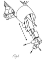
- the third axis of the manipulator unit is a telescopic arm - confer Fig. 6.
- the first axis corresponds to the rotation of the manipulator unit around the central axis of the carrier unit.
- the axis is energized by means of a motor in the carrier unit.
- the second axis is the shoulder of the telescopic arm.
- the connection is moved by means of a two linear motors comprising ball joints.
- the telescopic arm comprises three members for extension of the operational space and is operated by means of a ball joint.
- the use of ball joints to move the axes 2 and 3 ensures that said axes are not self-locking, whereby the built-in springs can retract the axes in case of a power failure.
- the end of the telescopic arm is provided with a "hand" on which the tools can be mounted.
- the tools may optionally be mounted directly on the end of the telescopic arm.
- the manipulator unit may be provided with two sets of monitoring cameras with light sources. Moreover, a connection box for tools is provided at the end of the telescopic arm.
- the manipulator unit can be provided with several different tools at the same time.
- Two sensors are used to monitor and control the robot. Two sensors are mounted on the carrier unit and one of these has a rear view, while the other has a side view. Two sensors are arranged on the arm of the manipulator unit (Fig. 6) and can be used to position the manipulator unit, to control the movements of the carrier unit and to monitor the tools.
- the positioning system for the robot is divided into the two systems, viz. a system for the carrier unit and a system for the manipulator unit.
- the two system are independent.
- the position system of the carrier unit provides the position of the carrier unit relative to a system of reference co-ordinates on the test piece
- the position system of the manipulator unit provides the absolute position of the tool used relative to the reference system on the carrier unit.
- the carrier unit is provided with three position monitoring systems.
- the carrier unit is moved to a position where the sensor recognizes a feature having a known position in the system of reference co-ordinates and the position of the carrier unit is altered on the basis of the position of this feature in the sensor display and the position of the sensor on the carrier unit, confer the position monitoring system No. 2.
- a sensor having a known position on the manipulator unit may be used for recalibration of the position of the carrier unit.
- the third position system is the gyroscopic position sensor.
- This sensor provides the position of the carrier unit in the working area relative to the position of the last calibration of the system.
- the sensor estimates the position by means of signals from three gyroscopes and three accelerometers. As the system is continuously operating, the actual position and the estimated position differs from each other. The difference per unit of time depends inter alia on external factors and the accuracy of the sensor. In order to eliminate the difference the senor can be recalibrated by means of the position monitoring system No. 2.
- all of axes of the manipulator unit are provided with coders.
- the control system of the manipulator unit can estimate the absolute position relative to the carrier unit.
- absolute coders it is not necessary to recalibrate the manipulator unit in case of a power supply failure.
- the control hardware of the robot comprises two circuits A and B.
- Circuit A is the main circuit controlling actuators connected to axes on the carrier unit and the manipulator unit.
- Circuit B is a secondary circuit controlling actuators connected to axes on the carrier unit and an axis 2 on the manipulator unit (for rotation of the telescopic arm). Both circuits operate during normal operation. If one of the circuits fails, the other circuit is still able to turn the telescopic arm to its retracted position and move the carrier unit at a reduced pressure on the legs.
- the circuits are provided with independent power supplies, electrical conductors and hoses in the main cable.
- the control electronics is formed of separate modules comprising control and communication electronics. The modules communicate through a local ring network.
- the communication in the ring network and between the ring network and a base station is controlled by a master module optionally connected to two driver modules. Additional driver modules can be connected to the system by means of auxiliary link modules comprising an additional communication computer and an additional power supply. Three different driver modules are used in the control hardware.
- a DC-motor driver unit is arranged in the same housing as the DC-motor, an independent DC-motor driver unit for three smaller DC-motors and a valve control driver for double-acting, pneumatic valves.
- the master module for the circuits A and B communicates with the computer of the control system via to serial interface connections.
- the control software of the robot controls and monitors the carrier unit as well as the manipulator unit.
- the control software of the robot for external monitoring has been developed by by means of ROBCAD open system Environment (ROSE) and ROBCAD/Martell (Monitoring and remote Teleoperating Environment) with ROBCAD CAD/CAM software.
- ROSE ROBCAD open system Environment
- ROBCAD/Martell Monitoring and remote Teleoperating Environment
- the control software of the carrier unit is one of the two parts of the control software of the system.
- the carrier unit can be operated independently or jointly with the manipulator unit. The following control options are available to the operator:
- Movement of the carrier unit enables the operator to move this backwards and forwards by means of predetermined guide lines. Moreover, the operator is able to control the rotation connection between the two parts of the carrier unit.
- the manipulator unit is controlled by the second part of the control software.
- the manipulator unit is controlled independently or jointly with the corresponding carrier unit.
Landscapes
- Engineering & Computer Science (AREA)
- General Engineering & Computer Science (AREA)
- Mechanical Engineering (AREA)
- Chemical & Material Sciences (AREA)
- Combustion & Propulsion (AREA)
- Manipulator (AREA)
Claims (6)
- Bewegbarer Roboter mit einer Trägereinheit und einer Manipulatoreinheit, von denen die Trägereinheit eine Axialbewegung in einer Rohrleitung bewirkt und zwei oder mehrere gegenseitig bewegbare Einheiten aufweist, wobei jede bewegbare Einheit vorzugsweise mit drei vorstehenden Beinen (4, 5) versehen ist, die Kontaktflächen (4a, 5a) zur Anlage an der Innenseite des Rohres haben, derart, dass die bewegbare Einheit relativ zu dem Rohr festgelegt ist, gekennzeichnet durch eine Drehverbindung und eine prismatische Verbindung, die die zwei oder mehreren gegeneinander bewegbaren Einheiten verbindet, wobei die prismatische Verbindung und die Drehverbindung durch unterschiedliche Mittel gesteuert werden, und dadurch, dass eine der bewegbaren Einheiten relativ zu dem Rohr festgelegt ist, wobei mindestens eine der anderen bewegbaren Einheiten relativ dazu bewegbar ist und die andere bewegbare Einheit relativ zu der festgelegten Einheit, die als ortsfester Bezug für die andere Einheit dient, drehbar sowie verschiebbar ist.
- Bewegbarer Roboter nach Anspruch 1, dadurch gekennzeichnet, dass jede Gruppe von Beinen entsprechend dem "Regenschirmprinzip" synchron in die Trägereinheit und aus der Trägereinheit bewegbar ist, um für eine Zentrierung der Trägereinheit zu sorgen.
- Bewegbarer Roboter nach Anspruch 1 - 2, dadurch gekennzeichnet, dass Sensoren wie Drucksensoren, die vorzugsweise in allen Richtungen wirksam sind, an den Kontaktflächen vorgesehen sind.
- Bewegbarer Roboter nach einem oder mehreren der vorhergehenden Ansprüche, dadurch gekennzeichnet, dass Sensoren wie Drucksensoren, die vorzugsweise in allen Richtungen wirksam sind, an der Manipulatoreinheit vorgesehen sind.
- Bewegbarer Roboter nach den Ansprüchen 1 bis 4, dadurch gekennzeichnet, dass die Trägereinheit mit zusätzlichen Sensoren wie Drucksensoren zum Erfassen von Hindernissen versehen ist.
- Verfahren zum Verwenden eines bewegbaren Roboters nach einem oder mehreren der vorhergehenden Ansprüche, dadurch gekennzeichnet, dass die Positionen der verschiedenen Hindernisse in der Rohrleitung gespeichert werden, um ein Bewegungsmuster zur Verwendung beim Zurückziehen des Roboters zu schaffen.
Applications Claiming Priority (3)
| Application Number | Priority Date | Filing Date | Title |
|---|---|---|---|
| DK78495 | 1995-07-04 | ||
| DK78495A DK173122B1 (da) | 1995-07-04 | 1995-07-04 | Bevægelig robot til indvendig inspektion af rør |
| PCT/DK1996/000298 WO1997002452A1 (en) | 1995-07-04 | 1996-07-02 | Movable robot for internal inspection of pipes |
Publications (2)
| Publication Number | Publication Date |
|---|---|
| EP0836694A1 EP0836694A1 (de) | 1998-04-22 |
| EP0836694B1 true EP0836694B1 (de) | 2002-01-23 |
Family
ID=8097522
Family Applications (1)
| Application Number | Title | Priority Date | Filing Date |
|---|---|---|---|
| EP96921920A Expired - Lifetime EP0836694B1 (de) | 1995-07-04 | 1996-07-02 | Fortbewegbarer roboter zur internen kontrolle von rohrleitungen |
Country Status (5)
| Country | Link |
|---|---|
| EP (1) | EP0836694B1 (de) |
| AU (1) | AU6299696A (de) |
| DE (1) | DE69618784T2 (de) |
| DK (1) | DK173122B1 (de) |
| WO (1) | WO1997002452A1 (de) |
Cited By (2)
| Publication number | Priority date | Publication date | Assignee | Title |
|---|---|---|---|---|
| US20130104676A1 (en) * | 2011-11-02 | 2013-05-02 | Industry-Academic Cooperation Foundation Yonsei University | In-pipe inspection robot |
| CN106027965A (zh) * | 2016-05-30 | 2016-10-12 | 中国科学院武汉岩土力学研究所 | 智能化数字式钻孔全景摄像装置的全景摄像方法 |
Families Citing this family (20)
| Publication number | Priority date | Publication date | Assignee | Title |
|---|---|---|---|---|
| ES2168522T3 (es) * | 1995-10-16 | 2002-06-16 | Framatome Anp Gmbh | Manipulador del interior de un tubo para revisar o tratar la superficie interior del mismo. |
| DE29712807U1 (de) * | 1997-07-19 | 1997-10-09 | Bölke, Klaus-Peter, Dipl.-Ing., 53757 Sankt Augustin | Vorrichtung zur visuellen Darstellung von Reinigungs-, Inspektions- und Sanierungsarbeiten |
| BR9904364A (pt) * | 1999-09-28 | 2001-06-05 | Petroleo Brasileiro Sa | Veìculo telecomandado para operações no interior de dutos |
| DE10215325A1 (de) * | 2002-04-02 | 2003-10-23 | Fraunhofer Ges Forschung | Roboter zur Inspektion und/oder Reinigung und/oder Sanierung von Kanälen |
| US20050223825A1 (en) * | 2004-01-16 | 2005-10-13 | Theo Janssen | Method to prevent rotation of caliper tools and other pipeline tools |
| EP1637833B1 (de) | 2004-09-20 | 2007-07-18 | Weatherford/Lamb, Inc. | Durchmesser Messgeräte |
| US7181985B2 (en) | 2005-05-27 | 2007-02-27 | Breval Technical Services Limited | Conduit inspection apparatus and method |
| US10427290B2 (en) | 2017-07-18 | 2019-10-01 | General Electric Company | Crawler robot for in situ gap inspection |
| US20090307891A1 (en) * | 2008-06-17 | 2009-12-17 | Ge-Hitachi Nuclear Energy Americas Llc | Method and apparatus for remotely inspecting and/or treating welds, pipes, vessels and/or other components used in reactor coolant systems or other process applications |
| DE102010044465A1 (de) * | 2010-09-06 | 2012-03-08 | I.S.T. Innovative Sewer Technologies Gmbh | Vorrichtung zum Sanieren eines Rohres |
| CN103399343B (zh) * | 2013-07-30 | 2017-05-03 | 刘焱 | 移动式传感器插置装置 |
| AT14204U1 (de) | 2013-11-28 | 2015-06-15 | Marko Taferner | Vorrichtung zum Prüfen von Leitungen |
| US10603802B2 (en) * | 2017-07-18 | 2020-03-31 | General Electric Company | End region inspection module and method for in situ gap inspection robot system |
| US10596713B2 (en) * | 2017-07-18 | 2020-03-24 | General Electric Company | Actuated sensor module and method for in situ gap inspection robots |
| US10434641B2 (en) | 2017-07-18 | 2019-10-08 | General Electric Company | In situ gap inspection robot system and method |
| US10427734B2 (en) | 2017-07-18 | 2019-10-01 | General Electric Company | Omnidirectional traction module for a robot |
| FR3079297B1 (fr) * | 2018-03-23 | 2020-07-17 | Framatome | Methode de determination de la position et/ou de l'orientation d'un robot/porteur evoluant dans une tuyauterie et ensembles associes |
| EP4018210B1 (de) | 2019-08-20 | 2026-01-14 | GE Vernova Technology GmbH | Visuelles inspektionsmodul mit doppelsichtbahnen für roboter |
| US12151751B2 (en) | 2019-08-20 | 2024-11-26 | Ge Infrastructure Technology Llc | Traction module for robot with variable extension positions |
| CN115302522A (zh) * | 2022-07-07 | 2022-11-08 | 浙江华仕管道科技有限公司 | 管道检测软体机器人 |
Family Cites Families (6)
| Publication number | Priority date | Publication date | Assignee | Title |
|---|---|---|---|---|
| FR2355236A1 (fr) * | 1976-05-20 | 1978-01-13 | Rouland Daniel | Dispositif de propulsion d'un mobile a l'interieur d'un corps tubulaire |
| DE3419683A1 (de) * | 1984-05-24 | 1985-11-28 | Mannesmann AG, 4000 Düsseldorf | Rohrmolch mit fahrwerken |
| US4581938A (en) * | 1984-07-30 | 1986-04-15 | Combustion Engineering, Inc. | Tool for scanning the inner surface of a large pipe |
| CH669127A5 (en) * | 1986-04-24 | 1989-02-28 | Eric Stucky | Traction device serving as mole running inside pipes - uses radially extended pivoted arms to act against walls of pipe either for locomotive movement or to lock mole |
| US4919223A (en) * | 1988-01-15 | 1990-04-24 | Shawn E. Egger | Apparatus for remotely controlled movement through tubular conduit |
| DE4302731C1 (de) * | 1993-02-01 | 1994-07-14 | Siemens Ag | Im Innern eines Rohres selbsttätig fortbewegbares Transportmittel |
-
1995
- 1995-07-04 DK DK78495A patent/DK173122B1/da not_active IP Right Cessation
-
1996
- 1996-07-02 EP EP96921920A patent/EP0836694B1/de not_active Expired - Lifetime
- 1996-07-02 WO PCT/DK1996/000298 patent/WO1997002452A1/en not_active Ceased
- 1996-07-02 DE DE69618784T patent/DE69618784T2/de not_active Expired - Fee Related
- 1996-07-12 AU AU62996/96A patent/AU6299696A/en not_active Abandoned
Cited By (4)
| Publication number | Priority date | Publication date | Assignee | Title |
|---|---|---|---|---|
| US20130104676A1 (en) * | 2011-11-02 | 2013-05-02 | Industry-Academic Cooperation Foundation Yonsei University | In-pipe inspection robot |
| US9021900B2 (en) * | 2011-11-02 | 2015-05-05 | Industry-Academic Cooperation Foundation Yonsei University | In-pipe inspection robot |
| CN106027965A (zh) * | 2016-05-30 | 2016-10-12 | 中国科学院武汉岩土力学研究所 | 智能化数字式钻孔全景摄像装置的全景摄像方法 |
| CN106027965B (zh) * | 2016-05-30 | 2022-03-18 | 中国科学院武汉岩土力学研究所 | 智能化数字式钻孔全景摄像装置的全景摄像方法 |
Also Published As
| Publication number | Publication date |
|---|---|
| DK173122B1 (da) | 2000-01-31 |
| WO1997002452A1 (en) | 1997-01-23 |
| DE69618784D1 (de) | 2002-03-14 |
| DK78495A (da) | 1997-01-05 |
| EP0836694A1 (de) | 1998-04-22 |
| DE69618784T2 (de) | 2002-09-12 |
| AU6299696A (en) | 1997-02-05 |
Similar Documents
| Publication | Publication Date | Title |
|---|---|---|
| EP0836694B1 (de) | Fortbewegbarer roboter zur internen kontrolle von rohrleitungen | |
| KR100494235B1 (ko) | 활선작업용 로봇차 및 그 제어방법 | |
| EP2781312B1 (de) | Werkzeugmaschine | |
| US9856037B2 (en) | Stabilization of an end of an extended-reach apparatus in a limited-access space | |
| FI123306B (fi) | Robottityökalujärjestelmä, sekä sen ohjausmenetelmä, tietokoneohjelma ja ohjelmistotuote | |
| US20240060592A1 (en) | Methods,systems, and apparatus for use in main pipes connected to branch conduit | |
| JP5291158B2 (ja) | 外骨格を有するcmmアーム | |
| US9862097B2 (en) | Industrial robot system having sensor assembly | |
| US7591078B2 (en) | CMM arm with exoskeleton | |
| US11992962B2 (en) | Robot and robot system | |
| WO2004007150A1 (ja) | 搬送用ロボットシステムおよび搬送用ロボットの制御方法 | |
| US20180290250A1 (en) | Automatic tool head placement and assembly apparatus for a boring machine | |
| CN110589011A (zh) | 一种用于飞机对接装配的新型球头球窝装置与入位方法 | |
| GB2100826A (en) | Remotely controlled arm | |
| JP7489805B2 (ja) | ロボットアーム | |
| CN213948633U (zh) | 一种用于将车身配件安装在车身上的安装系统 | |
| US20210114167A1 (en) | Grinding and/or Eroding Machine, and Method for Measuring and/or Referencing the Machine | |
| US12515824B2 (en) | Multi-function rendezvous and capture module | |
| Qiu et al. | Research on the Automatic Exchange Technology for Space Robot Manipulators |
Legal Events
| Date | Code | Title | Description |
|---|---|---|---|
| PUAI | Public reference made under article 153(3) epc to a published international application that has entered the european phase |
Free format text: ORIGINAL CODE: 0009012 |
|
| 17P | Request for examination filed |
Effective date: 19971218 |
|
| AK | Designated contracting states |
Kind code of ref document: A1 Designated state(s): DE DK ES FR GB SE |
|
| 17Q | First examination report despatched |
Effective date: 19990709 |
|
| GRAG | Despatch of communication of intention to grant |
Free format text: ORIGINAL CODE: EPIDOS AGRA |
|
| GRAG | Despatch of communication of intention to grant |
Free format text: ORIGINAL CODE: EPIDOS AGRA |
|
| GRAH | Despatch of communication of intention to grant a patent |
Free format text: ORIGINAL CODE: EPIDOS IGRA |
|
| GRAH | Despatch of communication of intention to grant a patent |
Free format text: ORIGINAL CODE: EPIDOS IGRA |
|
| GRAA | (expected) grant |
Free format text: ORIGINAL CODE: 0009210 |
|
| REG | Reference to a national code |
Ref country code: GB Ref legal event code: IF02 |
|
| RIN1 | Information on inventor provided before grant (corrected) |
Inventor name: KJUL, PETER Inventor name: VESTH, LARS Inventor name: HANSEN, PEDER, BENT |
|
| AK | Designated contracting states |
Kind code of ref document: B1 Designated state(s): DE DK ES FR GB SE |
|
| REF | Corresponds to: |
Ref document number: 69618784 Country of ref document: DE Date of ref document: 20020314 |
|
| PG25 | Lapsed in a contracting state [announced via postgrant information from national office to epo] |
Ref country code: DK Free format text: LAPSE BECAUSE OF FAILURE TO SUBMIT A TRANSLATION OF THE DESCRIPTION OR TO PAY THE FEE WITHIN THE PRESCRIBED TIME-LIMIT Effective date: 20020423 |
|
| RAP2 | Party data changed (patent owner data changed or rights of a patent transferred) |
Owner name: FORCE TECHNOLOGY Owner name: FORCE-INSTITUTTET |
|
| PGFP | Annual fee paid to national office [announced via postgrant information from national office to epo] |
Ref country code: FR Payment date: 20020627 Year of fee payment: 7 |
|
| PG25 | Lapsed in a contracting state [announced via postgrant information from national office to epo] |
Ref country code: GB Free format text: LAPSE BECAUSE OF NON-PAYMENT OF DUE FEES Effective date: 20020702 |
|
| ET | Fr: translation filed | ||
| PGFP | Annual fee paid to national office [announced via postgrant information from national office to epo] |
Ref country code: DE Payment date: 20020712 Year of fee payment: 7 |
|
| PGFP | Annual fee paid to national office [announced via postgrant information from national office to epo] |
Ref country code: SE Payment date: 20020715 Year of fee payment: 7 |
|
| PG25 | Lapsed in a contracting state [announced via postgrant information from national office to epo] |
Ref country code: ES Free format text: LAPSE BECAUSE OF FAILURE TO SUBMIT A TRANSLATION OF THE DESCRIPTION OR TO PAY THE FEE WITHIN THE PRESCRIBED TIME-LIMIT Effective date: 20020730 |
|
| PLBE | No opposition filed within time limit |
Free format text: ORIGINAL CODE: 0009261 |
|
| STAA | Information on the status of an ep patent application or granted ep patent |
Free format text: STATUS: NO OPPOSITION FILED WITHIN TIME LIMIT |
|
| 26N | No opposition filed | ||
| GBPC | Gb: european patent ceased through non-payment of renewal fee |
Effective date: 20020702 |
|
| PG25 | Lapsed in a contracting state [announced via postgrant information from national office to epo] |
Ref country code: SE Free format text: LAPSE BECAUSE OF NON-PAYMENT OF DUE FEES Effective date: 20030703 |
|
| PG25 | Lapsed in a contracting state [announced via postgrant information from national office to epo] |
Ref country code: DE Free format text: LAPSE BECAUSE OF NON-PAYMENT OF DUE FEES Effective date: 20040203 |
|
| EUG | Se: european patent has lapsed | ||
| PG25 | Lapsed in a contracting state [announced via postgrant information from national office to epo] |
Ref country code: FR Free format text: LAPSE BECAUSE OF NON-PAYMENT OF DUE FEES Effective date: 20040331 |
|
| REG | Reference to a national code |
Ref country code: FR Ref legal event code: ST |