EP0836801A2 - Tray - Google Patents
Tray Download PDFInfo
- Publication number
- EP0836801A2 EP0836801A2 EP97202412A EP97202412A EP0836801A2 EP 0836801 A2 EP0836801 A2 EP 0836801A2 EP 97202412 A EP97202412 A EP 97202412A EP 97202412 A EP97202412 A EP 97202412A EP 0836801 A2 EP0836801 A2 EP 0836801A2
- Authority
- EP
- European Patent Office
- Prior art keywords
- tray
- unit according
- carrier unit
- carrier
- rim
- Prior art date
- Legal status (The legal status is an assumption and is not a legal conclusion. Google has not performed a legal analysis and makes no representation as to the accuracy of the status listed.)
- Withdrawn
Links
Images

Classifications
-
- A—HUMAN NECESSITIES
- A01—AGRICULTURE; FORESTRY; ANIMAL HUSBANDRY; HUNTING; TRAPPING; FISHING
- A01G—HORTICULTURE; CULTIVATION OF VEGETABLES, FLOWERS, RICE, FRUIT, VINES, HOPS OR SEAWEED; FORESTRY; WATERING
- A01G9/00—Cultivation in receptacles, forcing-frames or greenhouses; Edging for beds, lawn or the like
- A01G9/02—Receptacles, e.g. flower-pots or boxes; Glasses for cultivating flowers
- A01G9/029—Receptacles for seedlings
- A01G9/0295—Units comprising two or more connected receptacles
Definitions
- the invention relates to a carrier unit comprising a tray, provided with cups to receice compressed plugs or loose fillings for the cultivation of sowing-seed.
- Such a carrier unit or tray is known in practice and is used for the cultivation of lettuce, cabbage plants and the like.
- the known carrier unit is formed of polystyrene foam shaped to contain cavities which form the cups that are filled with the sowing-seed.
- the known polystyrene trays are placed on inverted plant pots in a greenhouse.
- the use of this known carrier unit is rather primitive, and is a burden on the environment because of the use of polystyrene foam.
- carrier units made from hard plastic are also known.
- the known tray has a surface measure of about 60 x 40 cm in which the cups are provided to receive the compressed plugs or loose filling material with sowing-seed.
- the carrier unit according to the invention is characterized in that it is provided with at least two carrier elements which are detachably coupled to the tray. This allows the space in the greenhouse to be used much more efficiently while maintaining the effective placing space in the greenhouse. The space in the greenhouse that would otherwise be occupied by the carrier elements of the carrier unit has, by utilizing the invention, become effective greenhouse space.
- the carrier unit is preferably constructed such that each carrier element is substantially flat and is provided with supports placed perpendicularly on the surface of the carrier element, which supports are provided with recesses near the surface of the carrier element, serving to receive a rim of the tray.
- each carrier element is substantially flat and is provided with supports placed perpendicularly on the surface of the carrier element, which supports are provided with recesses near the surface of the carrier element, serving to receive a rim of the tray.
- a very desirable embodiment is one in which the tray possesses a longitudinally or circumferentially extending protective rim suitable for fitting into the recesses of the supports.
- This protective rim affords resistance against the shock load occurring in practice, so that there is less breakage and spoilage with regard to the trays in use.
- An additional advantage is that the protective rim can at the same time function as support rim when the supports are placed in said recesses.
- each carrier element comprises two supporting legs, each supporting leg being provided at its upper side with a projection and at its underside with a recess suitable to receive such a projection of another carrier element's supporting leg.
- This allows for a stable stacking of carrier elements.
- carrier units which each consist of one tray having at both end-on sides a carrier element, are placed on top of each other in stacks of 22 high, each tray filled with compressed plugs weighing about 5 to 6 kg.
- the tray should be provided with a protective rim in which evenly distributed first aeration holes are provided. This promotes aeration in the separate cups in the tray, which is a prerequisite for the intended application of cultivating sowing-seed.
- the protective rim is somewhat higher than the cups are deep, and that the tray at the upper side has a rim bounded by a ridge, which rim is able to support the under side of another tray's protective rim.
- the trays can easily be placed on top of each other without any problem for the sowing-seed on the trays thereunder.
- this embodiment provides a safeguard against the trays' shifting in relation to each other because the ridge extending along the inside of the protective rim belonging to the tray placed thereon provides a bond for the stack.
- aeration holes provided in the protective rim ensure that the sowing-seed in the underlying trays continue to be aerated. This is even furthered by the provision of second aeration holes in the upper surface of the tray at the intersection of adjacent cups.
- each cup is substantially square having round corners at the top and sharp corners in the bottom.
- the round corners thereby providing the tray with rigidity, while the sharp corners serve to guide the roots in the cup.
- top third of each cup exhibits an increased tapering from the top toward the bottom. This favours easy removal of the plant material.
- the tray between the adjacent cups is provided with tubes having round tops and which downwardly, past the tapering of the cups, finish square.
- These tubes, shaped as indicated, provide the tray construction with rigidity, so that in spite of the great strain exerted on it, it may be manufactured from relatively thin injection-moulding material.
- each cup in the round corners, at least in the part above the tapering, is provided with sharply defined guide channels to guide the roots.
- each cup at least one drainage hole is provided in the side of the bottom of each cup. This very effectively prevents the growth of a root mat at the bottom of the tray, so that after the sowing-seed has developed, the plugs can easily be removed from the tray.
- the invention is also embodied in a separate tray and a separate carrier element as described above, constituting part of the carrier unit.
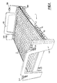
- Fig. 1 shows a carrier unit 1 comprising a tray 2 for the reception of compressed plugs or loose fillings in cups 3, wherein at its end-on sides the tray 2 is provided with carrier elements 4A and 4B. These carrier elements 4A and 4B are detachably coupled to the tray 2.
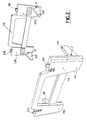
- each carrier element 4A , 4B is substantially flat and is provided with supports 5A, 5B and 6A, 6B placed perpendicularly on the surface of the carrier element 4A, 4B.
- These supports 5A, 5B, 6A, 6B are provided with recesses 7, 8 and 9 near the surface of the carrier elements 4A and 4B respectively.
- the recess of support 5B is not visible.
- Said recesses 7, 8, 9 serve to receive a rim of the tray 2.
- Fig. 1 shows that the tray 2 possesses a circumferentially extending protective rim 10, suitable for fitting into the recesses 7, 8, 9 of the supports 5A, 5B, 6A, 6B. It is also possible to provide this protective rim on both longitudinal sides of the tray only.
- the carrier element 4A, 4B comprises two supporting legs 11A, 12A and 11B, 12B. Each supporting leg 11A, 11B, 12A, 12B being provided at its upper side with a projection 13A, 13B, 14A, 14B and at its underside with a recess (not shown) suitable to receive such a projection of another carrier element's supporting leg, thus allowing a stable stacking of the carrier elements.
- Fig. 1 also shows that the protective rim 10 is provided with evenly distributed first aeration holes 15, and Fig. 5 shows that the protective rim is somewhat higher than the cups 16 are deep, and that the tray 2 at the upper side has a rim 17 bounded by a ridge 18, which rim 17 is able to support the under side of a protective rim 15 of another tray 2.
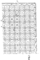
- Fig. 3 shows that in the upper surface of the tray 2 at the intersection of adjacent cups 16 second aeration holes 19 are provided.
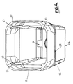
- Fig. 4 shows a single cup 16, and the square shape is clearly visible with round corners 20 at the top.
- the top third of the cup 16 exhibits an increased tapering 22 from the top 21 toward the bottom.
- this tapering 22 favours easy removal of the compressed plugs after the nursery material has been cultivated; on the other hand this makes it possible to provide the tray 2 between the adjacent cups 16 with tubes having round tops and which downwardly, past the tapering 22 of the cups, finishes square.
- Each cup 16 in the round corners 20, at least in the part above the tapering 22, is provided with sharply defined guide channels 23 to guide the roots. Also to aid guiding the roots, the cups 16 have at the bottom sharp instead of round corners.
- the cup 16 is further provided with at least one drainage hole 24.
Landscapes
- Life Sciences & Earth Sciences (AREA)
- Environmental Sciences (AREA)
- Cultivation Receptacles Or Flower-Pots, Or Pots For Seedlings (AREA)
Abstract
Description
Claims (14)
- A carrier unit (1) comprising a tray (2), provided with cups (16) to receive compressed plugs or loose fillings for the cultivation of sowing-seed, characterized in that it is provided with at least two carrier elements (4A, 4B) which are detachably coupled to the tray (2).
- A carrier unit according to claim 1, characterized in that each carrier element (4A, 4B) is substantially flat and is provided with supports (5A, 5B, 6A, 6B) placed perpendicularly on the surface of the carrier element (4A, 4B), which supports (5A, 5B, 6A, 6B) are provided with recesses (7, 8, 9) near the surface of the carrier element (4A, 4B), serving to receive a rim (10) of the tray (2).
- A carrier unit according to claim 1 or 2, characterized in that the tray (2) possesses a longitudinally or circumferentially extending protective rim (10), suitable for fitting into the recesses (7, 8, 9) of the supports (5A, 5B, 6A, 6B).
- A carrier unit according to claim 2, characterized in that each carrier element (4A, 4B) comprises two supporting legs (11A, 11B, 12A, 12B), each supporting leg being provided at its upper side with a projection (13A, 14A, 13B, 14B) and at its underside with a recess suitable to receive such a projection of another carrier element's supporting leg.
- A carrier unit according to claim 1, 2 or 3, characterized in that the tray (2) is provided with a protective rim (10) in which evenly distributed first aeration holes (15) are provided.
- A carrier unit according to claim 1-3 or 5, characterized in that the protective rim (10) is somewhat higher than the cups (16) are deep, and that the tray (2) at the upper side has a rim (17) bounded by a ridge (18), which rim (17) is able to support the under side of another tray's protective rim (10).
- A carrier unit according to claim 1-3, 5 or 6, characterized in that in the upper surface of the tray (2) at the intersection of adjacent cups (16) second aeration holes (23) are provided.
- A carrier unit according to claim 1-3, or 5-7, characterized in that each cup (16) is substantially square having round corners (20).
- A carrier unit according to claim 1-3, or 5-8, characterized in that the top third of each cup (16) exhibits an increased tapering (22) from the top (21) toward the bottom.
- A carrier unit according to claim 1-3, or 5-9, characterized in that the tray (2) between the adjacent cups (16) is provided with tubes having round tops and which downwardly, past the tapering of the cups, finish square.
- A carrier unit according to claim 1-3, or 5-10, characterized in that each cup in the round corners (20), at least in the part above the tapering (22), is provided with sharply defined guide channels (27) to guide the roots.
- A carrier unit according to claim 1-3, or 5-11, characterized in that in the side of the bottom of each cup (16) at least one drainage hole (24) is provided.
- Separate tray constituting part of the carrier unit according to one of the preceding claims.
- Separate carrier element constituting part of the carrier unit according to one of the preceding claims.
Applications Claiming Priority (2)
| Application Number | Priority Date | Filing Date | Title |
|---|---|---|---|
| NL1004299A NL1004299C2 (en) | 1996-10-17 | 1996-10-17 | Carrying unit. |
| NL1004299 | 1996-10-17 |
Publications (2)
| Publication Number | Publication Date |
|---|---|
| EP0836801A2 true EP0836801A2 (en) | 1998-04-22 |
| EP0836801A3 EP0836801A3 (en) | 1998-12-16 |
Family
ID=19763696
Family Applications (1)
| Application Number | Title | Priority Date | Filing Date |
|---|---|---|---|
| EP97202412A Withdrawn EP0836801A3 (en) | 1996-10-17 | 1997-08-01 | Tray |
Country Status (2)
| Country | Link |
|---|---|
| EP (1) | EP0836801A3 (en) |
| NL (1) | NL1004299C2 (en) |
Cited By (4)
| Publication number | Priority date | Publication date | Assignee | Title |
|---|---|---|---|---|
| WO2009116959A1 (en) * | 2008-03-18 | 2009-09-24 | Cem Aktas | A triple safe box system for production, transporting and stacking of seedlings |
| CN111071626A (en) * | 2020-01-07 | 2020-04-28 | 王平 | Rice planting sprout cultivation dish storage device |
| US10750674B2 (en) | 2016-05-10 | 2020-08-25 | Vineland Research And Innovation Centre | Air-root pruning propagation tray |
| NL2026808B1 (en) * | 2020-11-02 | 2022-06-27 | Dekker Chrysanten B V | Growing Tray |
Family Cites Families (7)
| Publication number | Priority date | Publication date | Assignee | Title |
|---|---|---|---|---|
| FR2050570A5 (en) * | 1969-06-20 | 1971-04-02 | Stamp | |
| FR2390088A1 (en) * | 1977-05-13 | 1978-12-08 | Mercier Pere Et Fils Ets | Installation for forcing endives - is built up of superposed vertically spaced platforms with drain openings in centre |
| IT207739Z2 (en) * | 1985-08-09 | 1988-02-08 | Resma Srl | CONTAINMENT STRUCTURE PARTICULARLY FOR HORTICULTURAL-FLORAL PLANTS. |
| NL8900418A (en) * | 1989-02-21 | 1990-09-17 | Veenman Simon J M | Seedling pots support table - has removable legs construction |
| US5022183A (en) * | 1989-07-31 | 1991-06-11 | Kord Products Limited | Flower pot carrying tray with restraining means for plural pots |
| NL9000926A (en) * | 1990-04-19 | 1991-11-18 | Dynoplast Bv | Basket container for pot plants - has removable corner supports enabling stacking or container |
| NZ244509A (en) * | 1991-09-30 | 1996-01-26 | David Victor Hawthorne | Plant pot with special shape to encourage structurally sound root formations |
-
1996
- 1996-10-17 NL NL1004299A patent/NL1004299C2/en not_active IP Right Cessation
-
1997
- 1997-08-01 EP EP97202412A patent/EP0836801A3/en not_active Withdrawn
Cited By (5)
| Publication number | Priority date | Publication date | Assignee | Title |
|---|---|---|---|---|
| WO2009116959A1 (en) * | 2008-03-18 | 2009-09-24 | Cem Aktas | A triple safe box system for production, transporting and stacking of seedlings |
| US10750674B2 (en) | 2016-05-10 | 2020-08-25 | Vineland Research And Innovation Centre | Air-root pruning propagation tray |
| CN111071626A (en) * | 2020-01-07 | 2020-04-28 | 王平 | Rice planting sprout cultivation dish storage device |
| CN111071626B (en) * | 2020-01-07 | 2022-01-04 | 广州顺生农业科技有限公司 | Rice planting sprout cultivation dish storage device |
| NL2026808B1 (en) * | 2020-11-02 | 2022-06-27 | Dekker Chrysanten B V | Growing Tray |
Also Published As
| Publication number | Publication date |
|---|---|
| NL1004299C2 (en) | 1998-04-20 |
| EP0836801A3 (en) | 1998-12-16 |
Similar Documents
| Publication | Publication Date | Title |
|---|---|---|
| US5581936A (en) | Plant propagation trays having inverted V-shaped aerated root separators | |
| US20070180766A1 (en) | Moisture absorbing and water transferring self watering structured stackable plant containers | |
| US4144672A (en) | Expanded plastic plant container with break-away bottom | |
| KR101470596B1 (en) | A Multi Purpose Assembling Flowerpot | |
| US6029399A (en) | Vertical bench | |
| GB2222063A (en) | Plant container assembly | |
| EP0836801A2 (en) | Tray | |
| US20020129551A1 (en) | Self-standing display device | |
| EP0205330B1 (en) | A holder for trays, pots, dishes or the like | |
| US3290820A (en) | Floral arranger | |
| WO2021044301A1 (en) | Modular planting system | |
| DK2880970T3 (en) | PLANT TRAY, UNITY PARTY OF THE TRAY AND AT LEAST A flowerpot, METHOD FOR ASSEMBLY OF A DEVICE AND METHOD FOR HANDLING OF flowerpots | |
| WO2003015496A2 (en) | Bulb container and method of planting | |
| GB2218887A (en) | Plant display system | |
| AU2023309578A1 (en) | Germinating and growth tray assembly for plant seeds | |
| JP7695733B1 (en) | Double-sided pot stand | |
| CN1969608A (en) | Flowerpot for arranging flowers and growing plants | |
| US12075736B1 (en) | Platform tray | |
| EP1208739A1 (en) | Flowerpot and support stick assembly for the same | |
| GB1569200A (en) | Combined removal tool and watering tray | |
| GB2211715A (en) | Container | |
| WO2004063020A2 (en) | Potted plant tray | |
| GB2158413A (en) | Potted plant pallet | |
| EP2014152B1 (en) | Flower pot and method of forming a flower pot | |
| AU780968B2 (en) | Improved carrier for plants |
Legal Events
| Date | Code | Title | Description |
|---|---|---|---|
| PUAI | Public reference made under article 153(3) epc to a published international application that has entered the european phase |
Free format text: ORIGINAL CODE: 0009012 |
|
| AK | Designated contracting states |
Kind code of ref document: A2 Designated state(s): BE DE DK ES FR GB IT LU NL |
|
| AX | Request for extension of the european patent |
Free format text: AL;LT;LV;RO;SI |
|
| PUAL | Search report despatched |
Free format text: ORIGINAL CODE: 0009013 |
|
| AK | Designated contracting states |
Kind code of ref document: A3 Designated state(s): AT BE CH DE DK ES FI FR GB GR IE IT LI LU MC NL PT SE |
|
| AX | Request for extension of the european patent |
Free format text: AL;LT;LV;RO;SI |
|
| AKX | Designation fees paid |
Free format text: BE DE DK ES FR GB IT LU NL |
|
| STAA | Information on the status of an ep patent application or granted ep patent |
Free format text: STATUS: THE APPLICATION IS DEEMED TO BE WITHDRAWN |
|
| 18D | Application deemed to be withdrawn |
Effective date: 19990617 |