EP0836834A2 - Révascularisation myocardiale assistée par laser non-synchronisée - Google Patents
Révascularisation myocardiale assistée par laser non-synchronisée Download PDFInfo
- Publication number
- EP0836834A2 EP0836834A2 EP97308237A EP97308237A EP0836834A2 EP 0836834 A2 EP0836834 A2 EP 0836834A2 EP 97308237 A EP97308237 A EP 97308237A EP 97308237 A EP97308237 A EP 97308237A EP 0836834 A2 EP0836834 A2 EP 0836834A2
- Authority
- EP
- European Patent Office
- Prior art keywords
- laser
- heart
- energy
- pulse
- laser energy
- Prior art date
- Legal status (The legal status is an assumption and is not a legal conclusion. Google has not performed a legal analysis and makes no representation as to the accuracy of the status listed.)
- Withdrawn
Links
- 230000002107 myocardial effect Effects 0.000 title claims abstract description 40
- 230000000250 revascularization Effects 0.000 title claims abstract description 35
- 238000000034 method Methods 0.000 claims abstract description 117
- 206010003119 arrhythmia Diseases 0.000 claims abstract description 55
- 210000004165 myocardium Anatomy 0.000 claims abstract description 41
- 230000004907 flux Effects 0.000 claims abstract description 26
- 230000000694 effects Effects 0.000 claims abstract description 21
- 230000000747 cardiac effect Effects 0.000 claims abstract description 14
- 230000001939 inductive effect Effects 0.000 claims abstract description 10
- 230000003685 thermal hair damage Effects 0.000 claims abstract description 8
- 238000007493 shaping process Methods 0.000 claims abstract description 6
- 239000013307 optical fiber Substances 0.000 claims description 41
- 230000017074 necrotic cell death Effects 0.000 claims description 24
- 210000005003 heart tissue Anatomy 0.000 claims description 23
- 229910052689 Holmium Inorganic materials 0.000 claims description 15
- KJZYNXUDTRRSPN-UHFFFAOYSA-N holmium atom Chemical compound [Ho] KJZYNXUDTRRSPN-UHFFFAOYSA-N 0.000 claims description 15
- XKRFYHLGVUSROY-UHFFFAOYSA-N Argon Chemical compound [Ar] XKRFYHLGVUSROY-UHFFFAOYSA-N 0.000 claims description 14
- 206010002383 Angina Pectoris Diseases 0.000 claims description 12
- 210000005166 vasculature Anatomy 0.000 claims description 11
- 229910052786 argon Inorganic materials 0.000 claims description 7
- 230000003287 optical effect Effects 0.000 claims description 6
- 230000001419 dependent effect Effects 0.000 claims description 5
- 230000009021 linear effect Effects 0.000 claims description 5
- 230000005855 radiation Effects 0.000 claims description 4
- 238000011282 treatment Methods 0.000 claims description 4
- 238000002604 ultrasonography Methods 0.000 claims description 4
- 230000000670 limiting effect Effects 0.000 claims description 2
- 230000006793 arrhythmia Effects 0.000 abstract description 32
- 208000014674 injury Diseases 0.000 abstract description 10
- 230000003247 decreasing effect Effects 0.000 abstract description 7
- 230000033001 locomotion Effects 0.000 abstract description 5
- 230000002411 adverse Effects 0.000 abstract description 4
- 239000002360 explosive Substances 0.000 abstract description 4
- 230000008733 trauma Effects 0.000 abstract description 4
- 230000005465 channeling Effects 0.000 abstract description 3
- 230000002123 temporal effect Effects 0.000 abstract 1
- 210000001519 tissue Anatomy 0.000 description 83
- 239000000835 fiber Substances 0.000 description 23
- 229910019655 synthetic inorganic crystalline material Inorganic materials 0.000 description 23
- 210000004027 cell Anatomy 0.000 description 21
- 210000001174 endocardium Anatomy 0.000 description 20
- 238000002679 ablation Methods 0.000 description 19
- 206010028851 Necrosis Diseases 0.000 description 18
- 230000035515 penetration Effects 0.000 description 15
- 238000010521 absorption reaction Methods 0.000 description 12
- 230000006378 damage Effects 0.000 description 12
- 230000033764 rhythmic process Effects 0.000 description 9
- XLYOFNOQVPJJNP-UHFFFAOYSA-N water Substances O XLYOFNOQVPJJNP-UHFFFAOYSA-N 0.000 description 9
- 238000010304 firing Methods 0.000 description 8
- 230000015572 biosynthetic process Effects 0.000 description 7
- 230000007246 mechanism Effects 0.000 description 7
- 208000027418 Wounds and injury Diseases 0.000 description 6
- 238000010009 beating Methods 0.000 description 6
- 239000008280 blood Substances 0.000 description 6
- 210000004369 blood Anatomy 0.000 description 6
- 230000001965 increasing effect Effects 0.000 description 6
- 210000005240 left ventricle Anatomy 0.000 description 6
- 230000001360 synchronised effect Effects 0.000 description 6
- 206010016654 Fibrosis Diseases 0.000 description 5
- 230000007423 decrease Effects 0.000 description 5
- 230000004761 fibrosis Effects 0.000 description 5
- 230000001678 irradiating effect Effects 0.000 description 5
- 230000037361 pathway Effects 0.000 description 5
- 230000009471 action Effects 0.000 description 4
- 230000004913 activation Effects 0.000 description 4
- 238000005520 cutting process Methods 0.000 description 4
- 238000004519 manufacturing process Methods 0.000 description 4
- 230000008569 process Effects 0.000 description 4
- 210000001013 sinoatrial node Anatomy 0.000 description 4
- 230000000451 tissue damage Effects 0.000 description 4
- 231100000827 tissue damage Toxicity 0.000 description 4
- 230000002763 arrhythmic effect Effects 0.000 description 3
- 210000001992 atrioventricular node Anatomy 0.000 description 3
- 230000009286 beneficial effect Effects 0.000 description 3
- 230000001276 controlling effect Effects 0.000 description 3
- 238000007429 general method Methods 0.000 description 3
- 230000003993 interaction Effects 0.000 description 3
- 238000012544 monitoring process Methods 0.000 description 3
- 210000003205 muscle Anatomy 0.000 description 3
- 210000000663 muscle cell Anatomy 0.000 description 3
- 238000005457 optimization Methods 0.000 description 3
- 230000002829 reductive effect Effects 0.000 description 3
- 230000004044 response Effects 0.000 description 3
- 102000008186 Collagen Human genes 0.000 description 2
- 108010035532 Collagen Proteins 0.000 description 2
- 229910052779 Neodymium Inorganic materials 0.000 description 2
- 230000002159 abnormal effect Effects 0.000 description 2
- 238000001467 acupuncture Methods 0.000 description 2
- JNDMLEXHDPKVFC-UHFFFAOYSA-N aluminum;oxygen(2-);yttrium(3+) Chemical compound [O-2].[O-2].[O-2].[Al+3].[Y+3] JNDMLEXHDPKVFC-UHFFFAOYSA-N 0.000 description 2
- QVGXLLKOCUKJST-UHFFFAOYSA-N atomic oxygen Chemical compound [O] QVGXLLKOCUKJST-UHFFFAOYSA-N 0.000 description 2
- 230000008901 benefit Effects 0.000 description 2
- 230000036760 body temperature Effects 0.000 description 2
- 206010061592 cardiac fibrillation Diseases 0.000 description 2
- 230000004087 circulation Effects 0.000 description 2
- 230000015271 coagulation Effects 0.000 description 2
- 238000005345 coagulation Methods 0.000 description 2
- 229920001436 collagen Polymers 0.000 description 2
- 238000001816 cooling Methods 0.000 description 2
- 239000003814 drug Substances 0.000 description 2
- 230000002526 effect on cardiovascular system Effects 0.000 description 2
- 238000005516 engineering process Methods 0.000 description 2
- 230000002600 fibrillogenic effect Effects 0.000 description 2
- 230000035876 healing Effects 0.000 description 2
- 210000002837 heart atrium Anatomy 0.000 description 2
- 230000004217 heart function Effects 0.000 description 2
- 230000001788 irregular Effects 0.000 description 2
- 238000012986 modification Methods 0.000 description 2
- 230000004048 modification Effects 0.000 description 2
- QEFYFXOXNSNQGX-UHFFFAOYSA-N neodymium atom Chemical compound [Nd] QEFYFXOXNSNQGX-UHFFFAOYSA-N 0.000 description 2
- 238000013021 overheating Methods 0.000 description 2
- 239000001301 oxygen Substances 0.000 description 2
- 229910052760 oxygen Inorganic materials 0.000 description 2
- 230000036961 partial effect Effects 0.000 description 2
- 230000000149 penetrating effect Effects 0.000 description 2
- 230000010287 polarization Effects 0.000 description 2
- 230000010349 pulsation Effects 0.000 description 2
- 238000005086 pumping Methods 0.000 description 2
- 230000035939 shock Effects 0.000 description 2
- 230000000638 stimulation Effects 0.000 description 2
- 238000001356 surgical procedure Methods 0.000 description 2
- 230000008016 vaporization Effects 0.000 description 2
- 238000009834 vaporization Methods 0.000 description 2
- 229910019901 yttrium aluminum garnet Inorganic materials 0.000 description 2
- OKTJSMMVPCPJKN-UHFFFAOYSA-N Carbon Chemical compound [C] OKTJSMMVPCPJKN-UHFFFAOYSA-N 0.000 description 1
- CURLTUGMZLYLDI-UHFFFAOYSA-N Carbon dioxide Chemical compound O=C=O CURLTUGMZLYLDI-UHFFFAOYSA-N 0.000 description 1
- 208000006017 Cardiac Tamponade Diseases 0.000 description 1
- 206010053567 Coagulopathies Diseases 0.000 description 1
- 206010010904 Convulsion Diseases 0.000 description 1
- 229910052691 Erbium Inorganic materials 0.000 description 1
- 206010061216 Infarction Diseases 0.000 description 1
- 102000002262 Thromboplastin Human genes 0.000 description 1
- 108010000499 Thromboplastin Proteins 0.000 description 1
- 208000007536 Thrombosis Diseases 0.000 description 1
- 238000000862 absorption spectrum Methods 0.000 description 1
- 238000009825 accumulation Methods 0.000 description 1
- 230000036982 action potential Effects 0.000 description 1
- 230000001154 acute effect Effects 0.000 description 1
- 210000002376 aorta thoracic Anatomy 0.000 description 1
- 238000013459 approach Methods 0.000 description 1
- 230000001746 atrial effect Effects 0.000 description 1
- 238000001574 biopsy Methods 0.000 description 1
- 230000017531 blood circulation Effects 0.000 description 1
- 230000036770 blood supply Effects 0.000 description 1
- 210000004375 bundle of his Anatomy 0.000 description 1
- 238000004364 calculation method Methods 0.000 description 1
- 229910052799 carbon Inorganic materials 0.000 description 1
- 229910002092 carbon dioxide Inorganic materials 0.000 description 1
- 230000001413 cellular effect Effects 0.000 description 1
- 230000008859 change Effects 0.000 description 1
- 230000035602 clotting Effects 0.000 description 1
- 238000004891 communication Methods 0.000 description 1
- 239000000470 constituent Substances 0.000 description 1
- 230000036461 convulsion Effects 0.000 description 1
- 210000004351 coronary vessel Anatomy 0.000 description 1
- 230000002596 correlated effect Effects 0.000 description 1
- 230000001186 cumulative effect Effects 0.000 description 1
- 230000001351 cycling effect Effects 0.000 description 1
- 230000002939 deleterious effect Effects 0.000 description 1
- 238000001514 detection method Methods 0.000 description 1
- 238000010586 diagram Methods 0.000 description 1
- 238000009792 diffusion process Methods 0.000 description 1
- 230000003292 diminished effect Effects 0.000 description 1
- 229940079593 drug Drugs 0.000 description 1
- 210000003038 endothelium Anatomy 0.000 description 1
- UYAHIZSMUZPPFV-UHFFFAOYSA-N erbium Chemical compound [Er] UYAHIZSMUZPPFV-UHFFFAOYSA-N 0.000 description 1
- 230000005284 excitation Effects 0.000 description 1
- 210000001105 femoral artery Anatomy 0.000 description 1
- 210000002950 fibroblast Anatomy 0.000 description 1
- 239000012530 fluid Substances 0.000 description 1
- 239000007789 gas Substances 0.000 description 1
- 210000004013 groin Anatomy 0.000 description 1
- 238000003384 imaging method Methods 0.000 description 1
- 238000001727 in vivo Methods 0.000 description 1
- 230000007574 infarction Effects 0.000 description 1
- 230000028709 inflammatory response Effects 0.000 description 1
- 208000028867 ischemia Diseases 0.000 description 1
- 238000013532 laser treatment Methods 0.000 description 1
- 210000002540 macrophage Anatomy 0.000 description 1
- 239000000463 material Substances 0.000 description 1
- 230000001404 mediated effect Effects 0.000 description 1
- 230000004089 microcirculation Effects 0.000 description 1
- 210000000107 myocyte Anatomy 0.000 description 1
- 235000015097 nutrients Nutrition 0.000 description 1
- 230000008520 organization Effects 0.000 description 1
- 238000012545 processing Methods 0.000 description 1
- 230000001902 propagating effect Effects 0.000 description 1
- 210000003742 purkinje fiber Anatomy 0.000 description 1
- 230000009467 reduction Effects 0.000 description 1
- 230000003252 repetitive effect Effects 0.000 description 1
- 230000000284 resting effect Effects 0.000 description 1
- 210000005245 right atrium Anatomy 0.000 description 1
- 210000005241 right ventricle Anatomy 0.000 description 1
- 231100000241 scar Toxicity 0.000 description 1
- 210000004872 soft tissue Anatomy 0.000 description 1
- 239000000758 substrate Substances 0.000 description 1
- 230000001225 therapeutic effect Effects 0.000 description 1
- 239000010409 thin film Substances 0.000 description 1
- 208000037816 tissue injury Diseases 0.000 description 1
- 238000012546 transfer Methods 0.000 description 1
- 230000000472 traumatic effect Effects 0.000 description 1
- 238000012285 ultrasound imaging Methods 0.000 description 1
- 210000002620 vena cava superior Anatomy 0.000 description 1
- 230000002861 ventricular Effects 0.000 description 1
- 238000012800 visualization Methods 0.000 description 1
Images


Classifications
-
- A—HUMAN NECESSITIES
- A61—MEDICAL OR VETERINARY SCIENCE; HYGIENE
- A61B—DIAGNOSIS; SURGERY; IDENTIFICATION
- A61B18/00—Surgical instruments, devices or methods for transferring non-mechanical forms of energy to or from the body
- A61B18/18—Surgical instruments, devices or methods for transferring non-mechanical forms of energy to or from the body by applying electromagnetic radiation, e.g. microwaves
- A61B18/20—Surgical instruments, devices or methods for transferring non-mechanical forms of energy to or from the body by applying electromagnetic radiation, e.g. microwaves using laser
- A61B18/22—Surgical instruments, devices or methods for transferring non-mechanical forms of energy to or from the body by applying electromagnetic radiation, e.g. microwaves using laser the beam being directed along or through a flexible conduit, e.g. an optical fibre; Couplings or hand-pieces therefor
- A61B18/24—Surgical instruments, devices or methods for transferring non-mechanical forms of energy to or from the body by applying electromagnetic radiation, e.g. microwaves using laser the beam being directed along or through a flexible conduit, e.g. an optical fibre; Couplings or hand-pieces therefor with a catheter
-
- A—HUMAN NECESSITIES
- A61—MEDICAL OR VETERINARY SCIENCE; HYGIENE
- A61B—DIAGNOSIS; SURGERY; IDENTIFICATION
- A61B17/00—Surgical instruments, devices or methods
- A61B17/00234—Surgical instruments, devices or methods for minimally invasive surgery
- A61B2017/00238—Type of minimally invasive operation
- A61B2017/00243—Type of minimally invasive operation cardiac
- A61B2017/00247—Making holes in the wall of the heart, e.g. laser Myocardial revascularization
-
- A—HUMAN NECESSITIES
- A61—MEDICAL OR VETERINARY SCIENCE; HYGIENE
- A61B—DIAGNOSIS; SURGERY; IDENTIFICATION
- A61B17/00—Surgical instruments, devices or methods
- A61B2017/00681—Aspects not otherwise provided for
- A61B2017/00694—Aspects not otherwise provided for with means correcting for movement of or for synchronisation with the body
- A61B2017/00703—Aspects not otherwise provided for with means correcting for movement of or for synchronisation with the body correcting for movement of heart, e.g. ECG-triggered
-
- A—HUMAN NECESSITIES
- A61—MEDICAL OR VETERINARY SCIENCE; HYGIENE
- A61B—DIAGNOSIS; SURGERY; IDENTIFICATION
- A61B18/00—Surgical instruments, devices or methods for transferring non-mechanical forms of energy to or from the body
- A61B2018/00315—Surgical instruments, devices or methods for transferring non-mechanical forms of energy to or from the body for treatment of particular body parts
- A61B2018/00345—Vascular system
- A61B2018/00351—Heart
- A61B2018/00392—Transmyocardial revascularisation
Definitions
- the present invention relates to a procedure known as laser-assisted myocardial revascularization, and more particularly, to improved methods for revascularization of the heart by creating a plurality of small pathways or channels through predetermined portions of the heart using laser energy delivered via a laser delivery means according to specific parameters, including variable frequency, and without requiring synchronization of laser energy delivery with the beating of the heart.
- TMR transmyocardial revascularization
- PTMR percutaneous transluminal myocardial revascularization
- U.S. Patent No. 4,658,817 issued Apr. 21, 1987 to Hardy teaches a method and apparatus for TMR using a surgical CO 2 laser including a handpiece for directing a laser beam to a desired location.
- Hardy suggests that the creation of TMR channels using a laser may affect contractility of the heart and states that the number of perforations may have to be limited accordingly.
- Rudko et al teaches a heart-synchronized pulsed laser system for TMR. Utilizing electrical sensing, the heart beat is monitored using an EKG device. The device automatically delivers what appears to be a square pulse of laser energy to the heart only in response to electrical detection of a predetermined portion of the heartbeat cycle.
- An arrhythmia is a disturbed heart rhythm which often takes over as the primary rhythm of the heart, as evidenced by a rapid flutter or other rhythm of the heart muscle, which renders it ineffective at pumping blood through the vasculature.
- the process of delivering laser energy to tissue results in polarization of individual cells of the heart in the area of delivery of the laser energy. Polarization of the specialized conducting cells as well as myocardial cells drives the action potential of cells resulting in responsive contractile motion. Delivering laser energy can disrupt the normal rhythm of the heartbeat since the cardiac rhythm can be side-tracked to that of the polarized cells as opposed to propagating through the heart along the normal path of the impulse.
- the heart's natural, primary pacemaker is found in a group of cells called the sinoatrial or sinus node located near the junction of the superior vena cava and the right atrium.
- the electrical impulse originates in the endocardium and propagates through the myocardium to the epicardial surface.
- the electrical impulse is conducted out of the sinus node to the atria, where it stimulates atrial muscle cells to contract, and to the atrioventricular node.
- the electrical impulse Upon leaving the atrioventricular node, the electrical impulse continues to propagate down the conducting system to the bundle of His, into right and left branches thereof.
- the right bundle spreads the electrical impulse to the right ventricle and the left bundle branch propagates the impulse to anterior and posterior positions in the left ventricle to reach the Purkinje fibers.
- These small fibers form a rapid conduction network through the myocardium to deliver the impulse to all of the individual contractile muscle cells of the myocardium.
- the electrical signal travels at different speeds at different parts of the network. While electrical signals on the portion of the network extending through the atria have been found to travel at velocities of about 1 meter per second, these signals slow to about 0.2 m/s as they pass through the atrioventricular node. Signal propagation through the ventricular Purkinje network, however, is much faster - approximately 4 m/s. Thus, the sinus node is responsible for producing a repeating electrical impulse which ultimately causes the muscle cells of the heart to contract in repetitive, wave-like convulsions.
- the synchronization solutions proposed in the prior art discussed above do not address methods for detecting and compensating for hard to detect, abnormal conduction patterns or rhythms which may occur in damaged hearts. Additionally, EKG monitoring may not detect and allow compensation for localized or isolated areas of heart tissue which may not be synchronized with other areas of heart tissue. Excitation of such isolated areas may cause arrhythmias.
- heart synchronization as described in the prior art limits the amount of time the laser can be activated during a heart cycle, thereby increasing the time of a TMR procedure.
- Embodiments of the invention desirably facilitate a method for performing both transmyocardial revascularization (TMR) and percutaneous transluminal myocardial revascularization (PTMR) with laser energy having parameters selected to avoid cardiac arrhythmia.
- TMR transmyocardial revascularization
- PTMR percutaneous transluminal myocardial revascularization
- a method for TMR and PTMR with laser energy having parameters selected to avoid cardiac arrhythmia comprises the following steps, in combination of: determining a wavelength of the laser energy from a laser selected to perform either TMR or PTMR; using the wavelength determination to select parameters for the laser energy to produce a non-square wave shape; generating the laser energy at the determined wavelength with the selected parameters to produce the non-square wave shape; and delivering the generated laser energy in one or more pulses to selected portions of heart tissue to perform either TMR or PTMR in the myocardium without inducing cardiac arrhythmia and without synchronizing delivery of the laser energy to a cardiac cycle. site.
- the selected parameters are power level, energy flux, pulse width, and pulse frequency.
- the laser energy has a wavelength of between about 1.8 and about 2.2 microns, an energy flux of between 0.7-1.78 J/mm 2 and a power level of at least about 3 watts, the laser energy being delivered with a pulse frequency of at least about 5 Hertz and a pulse width of between about 150 and about 350 millisecond, the laser energy as delivered causing about 5 millimeters or less lateral necrosis surrounding a TMR treatment.
- the laser energy When using a Xe:Cl excimer laser in either a TMR or PTMR procedure, the laser energy has a wavelength of about 0.308 microns, a power level of between 0.3- 2.0 watts and an energy flux of between about 25-80 mJ/mm 2 , and is delivered with a pulse frequency of between about 5-25 Hz and a pulse width of between about 20-200 microseconds, and causes about 5 microns lateral necrosis surrounding the TMR channel produced thereby.
- the laser energy When using a CO 2 laser for the TMR procedure, the laser energy has a wavelength of about 10.6 microns, an energy flux of about 51 J/mm 2 and a power level at least about 800 W, is delivered in a single pulse about of 0.05 seconds and can be gated, and causes between about 0.03 to about 0.2 millimeters lateral necrosis surrounding a TMR channel produced.
- the laser energy When using an Argon laser for TMR, the laser energy has a wavelength of between about 0.488 and about 0.514 microns, an energy flux of about 1.3-12.74 J/mm 2 and a power level at least about 1-10 W, is delivered in a single pulse, and causes approximately 4 mm lateral necrosis surrounding a TMR channel produced thereby, and is generated by an Argon laser.
- the laser energy When using a Nd:YAG laser in a TMR procedure, the laser energy has a wavelength of about 1.06 microns, an energy flux of about 9.5-13 J/cm 2 and a power level at least about 2-100 W, is delivered with a pulse frequency of about 1-10 Hz and a pulse width of about 10 nanoseconds, and causes at least about 15 mm lateral necrosis surrounding a TMR channel produced thereby.
- the laser energy When using an Er:YAG laser for the TMR procedure, the laser energy has a wavelength of about 2.94 microns, an energy flux of about 50-500 J/mm 2 , is delivered with a pulse frequency of about 1-15 Hertz and a pulse width of about 1-250 microseconds, and causes about 0.1 millimeters lateral necrosis surrounding a TMR channel produced by an Er:YAG laser.
- laser energy is delivered to selected portions of heart tissue by surgically accessing the selected portions and positioning the laser delivery means at an epicardial surface of the heart tissue.
- the epicardial surface adjacent the selected portions of heart tissue may be mechanically pierced prior to delivering the laser energy into the myocardium.
- the laser energy is delivered to the selected portions of heart tissue using a catheter apparatus with laser delivery means, the method further comprising the following steps of introducing the catheter apparatus with laser delivery means percutaneously into the vasculature of the patient; and positioning the laser delivery means at the endocardial surface of the selected portions of heart tissue.
- the laser energy is delivered to the selected portions of heart tissue in a procedure using laser delivery means where the revasculature site is accessed by positioning the laser delivery means at an endocardial surface of the heart tissue through inside a patient's coronary artery.
- the method further includes the step of mechanically piercing the endocardial and/or myocardial layer heart tissue prior to delivering the laser energy into the myocardium thereby creating a welling affect by the surrounding endocardial tissue.
- the method further includes mechanically piercing the endocardial surface adjacent the selected portions of heart tissue prior to delivering the laser energy into the myocardium and penetrating no more than half the wall thickness of the myocardium.
- the TMR method comprises the following steps of generating laser energy having a non-square wave shape, a selected wavelength, a selected energy flux and a selected power level; and delivering the laser energy in a plurality of pulses, the plurality of pulses having a selected pulse frequency and a selected pulse width, to selected portions of myocardium without cardiac arrhythmia and without synchronizing delivery of the laser beam with the cardiac cycle.
- a variable number of pulses of laser energy is delivered with a variable pulse frequency between 5-20 Hz.
- the laser energy is delivered with a variable pulse repetition rate of between about 1 and 10 pulses.
- the laser energy is delivered with a constant pulse frequency of between about 5 and 20 Hertz and a variable pulse preset limit of between about 1-10 pulses.
- the laser energy is delivered in a pulsed mode at a high repetition rate of fixed frequency, the method using a laser with an optical shutter and in which the shutter of the laser is opened and closed in response to a random sequence of commands.
- the pulsed laser energy is delivered in a pulsed mode pulsed at a high repetition rate of fixed frequency, the method using a laser with a controllable flashlamp and in which the flashlamp is allowed to fire only during certain pulses within the fixed frequency laser operation in response to a random sequence of commands.
- the laser energy is delivered in a pulsed mode pulsed at a random, variable frequency rate.
- the invention provides a method of percutaneous transluminal myocardial revascularization of a patient's myocardium for relieving angina and avoiding cardiac arrhythmia, comprising the steps of:
- the step of irradiating the inner wall of the heart uses the optical fiber that is between 600-1100 microns in diameter and pulsation number is between 2-5 pulses with an average laser power of 3.5 watts.
- the step of directing the distal end of the lasing apparatus to an area within the patient's heart may comprise placement of the optical fiber end at the endocardial wall prior to the step of laser irradiation.
- the step of directing the distal end of the lasing apparatus to an area within the patient's heart comprises the step of piercing the optical fiber end partially through the endocardial wall or totally through the endocardial layer prior to the step of laser irradiation.
- the step of directing the distal end of the lasing apparatus to an area within the patient's heart comprises having the optical fiber end pierce totally through the endocardial layer and part way into the myocardial tissue and the average power level setting is reduced prior to the step of laser irradiation.
- the method further includes a step of progressively advancing the optical fiber end between successive laser pulses.
- the method further includes a step of providing an ultrasound device for determining a position of the fiber optical end with respect to a ventricle wall prior to each laser pulse emission.
- the invention provides a method of percutaneous transluminal myocardial revascularization of a patient for relief from angina while avoiding cardiac arrhythmia during the procedure, comprising the steps of:
- the step of directing the distal end of the lasing apparatus to an area within the heart to be revascularized comprises engaging the optical fiber's end by piercing the endocardial wall surface with the optical fiber's end.
- a method of percutaneous transluminal myocardial revascularization of a patient's heart for relieving angina and avoiding cardiac arrhythmia comprising the steps of:
- the method further includes a step of providing an ultrasound device for determining a position of the distal end with respect to a ventricle wall prior to each laser pulse.
- the invention provides a method of percutaneous transluminal myocardial revascularization of a patient's heart for relieving angina and avoiding cardiac arrhythmia, comprising the steps of:
- the number of pulses is less than ten and the optical fiber's distal end is approximately 1 mm in diameter.
- the present invention provides a method of selecting laser parameters for performing laser-assisted TMR or PTMR procedure to avoid cardiac arrhythmia and without synchronization of delivery of laser energy to a patient's cardiac cycle.
- the method comprises the following steps, in combination: selecting a minimum power level of laser energy to be used, the minimum power level being sufficient to ablate heart tissue; setting a pulse frequency as great as possible and selected to avoid summation effects; setting a pulse width as long as possible and selected to prevent excessively high peak power without causing undesired levels of thermal damage during TMR or PTMR; shaping a front end of each pulse of laser energy to provide non-linear pulses to avoid cardiac arrhythmia during TMR; and correcting the selected power level, pulse width, pulse frequency, pulse width, and shaping for mechanical events.
- the selected parameters are a single pulse, power level, energy flux, and pulse width.
- the depth of channel formed by no more than half the wall thickness of a patient's myocardium it is preferred that the depth of channel formed by no more than half the wall thickness of a patient's myocardium.
- FIGS. 1A-1C are graphical representations of the process of summation.
- FIGS. 2A and 2B are graphical comparisons of the resultant difference between ablation with a square wave versus ablation with a non-square wave.
- FIG. 3 is a flow chart demonstrating a method of selecting and setting variable laser parameters.
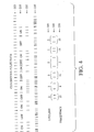
- FIG. 4 is a representative example of variable laser parameters.
- This invention teaches laser parameters which, in optimized combinations, reduce or eliminate the risk of inducing arrhythmia while performing a laser-assisted TMR and PTMR.
- the methods described herein do not require cardiac monitoring or any other form of synchronization of laser delivery with the natural cardiac rhythm.
- the present invention is intended for use with any medical laser.
- excimer and Holmium lasers including many of various different types known and available now or at any time, are particularly suited to the present invention.
- any suitable laser source, pulsed or otherwise may be used to provide laser energy to the laser delivery means of the present invention for performing the method of the present invention.
- laser sources include but are not limited to CO 2 , argon, neodymium: yttrium aluminum garnet (Nd:YAG) as well as erbium: yttrium aluminum garnet (Er:YAG).
- the following laser operating parameters have been determined to be optimal parameters for performing laser-assisted revascularization without causing arrhythmias.
- Single pulse, CW or superpulsed CW-multimode can be q-switched or gated 1-10 Hz; CW or pulsed; CW can be "gated” 1-15 Hz Energy Flux About 25-80 mJ/mm 2 About 0.7-1.78 J/mm 2 About 51 J/mm 2 About 1.3-12.75 J/mm 2 About 9.5-13 J/cm 2 pulsed; About. 8-27 J/mm 2 CW About 50-500 J/mm Laser Pulse Width About 20-200 ns About 150-350 ⁇ s About 0.05 s N/A 10 ns, CW or pulsed About 1-250 ⁇ s Wave Shape Non-square Non-square Non-square N/A Non-square Ave.
- the above laser operating parameters for various types of lasers were selected to enable laser energy to smoothly and gradually interact with the tissue of the heart thereby avoiding, where possible, sharp and sudden tissue interaction.
- a contoured, smooth, gradual application of energy will provide less shock to the heart itself.
- a non-square wave with a relatively shorter pulse width generally is preferred to achieve such smooth and gradual tissue interaction. It will be recognized by those skilled in the art that achieving the desire effect requires variation of the individual elements of the laser operating parameters depending upon the type of laser selected. Each laser operating parameter is discussed separately below.
- the tissue vaporizes. Since water is the primary constituent of most soft tissue, about 80% or more, the correlation is fairly accurate, although there will be minor differences between absorption of mid-infrared energy in water and in tissue, as well as between different types of tissue. The mid-infrared absorption spectrum of water is well known and absorption coefficients over a larger range are available.
- the absorption coefficient ⁇ of the 2.1 micron Holmium:YAG laser is about 26 cm -1 . This modality is highly efficacious for cutting and ablating.
- the absorption coefficients of the 1.06 micron wavelength energy created by the Neodymium:YAG laser and the 10.6 micron radiation produced by a CO 2 laser are 0.13 and 823 cm -1 , respectively.
- a large absorption coefficient implies a short penetration depth. Penetration is short because the energy is immediately absorbed by the cells closest to the source and does not extend into the tissue.
- lasers include the Xe:Cl excimer laser which delivers energy at 0.308 ⁇ m, the argon laser which delivers energy at between about 0.488-0.514 ⁇ m, the CO 2 laser which delivers energy at 10.6 ⁇ m, and the Nd:YAG laser which delivers energy at 1.06 ⁇ m.
- CO 2 lasers used in a fluid environment in near-contact procedures have the disadvantage in that even a thin film of water between the fiber and the tissue will greatly diminish the effective laser power because of the large absorption coefficient.
- the use of gas insufflation is generally required with the CO 2 laser.
- CO 2 lasers generally require further manipulation of parameters to create TMR channels.
- pulse widths less than about 300 milliseconds, and preferably lower than about 200 milliseconds have been found to be most effective.
- frequency rates greater than 5 hertz and preferably between about 5 hertz and about 25 hertz are least likely to induce electrical arrhythmia during TMR.
- the Holmium:YAG or other comparable pulsed laser can be pulsed at a certain rate or within a range of rates. Pulsed application of laser energy to effect vaporization and ablation of the tissue has been demonstrated to be preferable in some instances to application of laser energy in a single pulse.
- a given volume of tissue will absorb laser energy converting it into heat.
- a certain minimum rate of delivery of energy is required to counteract the effect of thermal relaxation which is the phenomenon by which heat diffuses out of the heated volume of tissue.
- the thermal relaxation time T is defined as the amount of time required for a given amount of heat to diffuse out of a given volume of tissue.
- the pulse width must be optimized to prevent a peak power spike while achieving a predetermined energy flux for ablation or any other procedure. Too short a duration will require too sharp an energy spike with a very high peak power level. On the other hand, too long a pulse will result in summation of energy effects which result in overheating, an increased zone of thermal necrosis, and possible other coagulation type effects.
- Nd:YAG, Ho:YAG, Xe:Cl excimer and Er:YAG lasers are all pulsed lasers in at least preferred forms, and therefore optimum pulse widths may be selected. Appropriate pulsing will avoid summation effects and will provide a contoured, gentle leading edge of the energy delivery profile.
- a continuous wave laser such as argon, some Nd:YAG and some CO 2 lasers
- Use of a continuous wave laser typically can be enhanced by mechanically chopping the continuous wave to reduce unfavorable thermal effects.
- the advantage to chopping such laser beams is to reduce or eliminate adverse summation effects on the tissue.
- mechanically chopping a continuous wave does make it more difficult to achieve a non-square or otherwise less assaultive delivery of laser energy.
- the rate at which it is delivered is also important. Too narrow of a pulse width at too low of a power level will fail to create patent channels.
- the power of the laser beam, or the amount of energy delivered to the tissue in terms of Joules per second is also an important factor to consider.
- optimal pulse frequencies and pulse widths to avoid arrhythmias combine to create a relatively narrow pulse width delivered at a relatively high pulse frequency.
- Energy flux E pulse or fluence also referred to as radiant exposure or energy density, is expressed in units of pulse energy per area, or joules per square centimeter.
- the threshold radiant exposure F th is defined as the single pulse threshold for the ablation of biologic tissue. For radiant exposures less than this threshold, tissue is not vaporized or ablated, but, instead, is heated. For radiant exposures higher than this threshold, tissue is vaporized. Thus, for effective ablation, the energy per pulse divided by the area of the spot size must be greater than the threshold radiant exposure.
- the threshold energy per unit volume for water is known to be 2500 joules per cubic centimeter. This is also the heat of vaporization, or the heat required to raise one cubic centimeter from about body temperature to steam at 100 degrees centigrade. This threshold energy per unit volume is given by the equations: F th x ⁇ or F th / d
- Depth of penetration is equal to the inverse of the absorption coefficient and the threshold radiant exposure for biologic tissue is about 100 joules per square centimeter. An effective energy flux must be at least this great. Experimentally, threshold energy flux rates of between about 5 and 75 joules per square centimeter are found.
- the number of tissue parcels ablated per second is equal to the repetition rate of the laser in pulses per second, or hertz.
- a region of tissue is illuminated by more than one pulse, an excess of energy accumulates in the tissue.
- the individual pulse energy and spot size provide an energy flux below the single pulse threshold radiant exposure F th , but the interval between pulses at a particular repetition rate is shorter than the characteristic thermal relaxation time T, a parcel or given volume of tissue may be ablated after a number of pulses has impinged the tissue. This process is referred to as summation.
- FIGS. 1A-1C are graphical representations of the process of summation.
- an initial pulse of energy 80 increases the temperature (T) of the tissue locally.
- T temperature
- t time between pulses
- the temperature of the tissue drops rapidly and immediately at 82 during the beginning of the delay period ( D ) following irradiation with no net result.
- D delay period following irradiation with no net result.
- An initial pulse of energy 84 increases the local temperature to a certain point 86 , and then the temperature begins to drop during the time period 88 immediately following the first irradiation step.
- another pulse of laser energy is delivered to impinge upon the tissue.
- the additional pulse elevates the temperature from temperature level 90 to a temperature 91 which is high enough to cause ablation.
- Repeated cycling as in Fig. 1B is very effective at achieving ablation without causing excess thermal damage in the surrounding tissue.
- the system can be described with the following equation: (P av /A) - (F th / ⁇ ) > 0 (It should be noted that F th may not remain constant in this regime: only the first pulse encounters fully hydrated, native tissue at body temperature.) Effectively, this criterion indicates that ablation can generally take place only if energy is supplied faster than it diffuses away.
- the interval between pulses can be as short as between 20 and 50 milliseconds, which is shorter than the shortest thermal relaxation time that arises from laser interaction with biologic tissue.
- a repetition rate greater than 3.5 hertz will permit entry into this Fig. 1B regime, however, as described above, pulse frequencies of between 5 and 15 hertz are optimum for laser-assisted TMR in which the risk of electrical arrhythmia is optimally reduced.
- an average power delivery will be greater than 6 watts, or 6 joules per second.
- the power of the laser used, or the rate of delivery of energy to the tissue can be tailored to avoid collateral damage of subsequent pulses.
- summation and overheating are more of a problem with continuous wave lasers
- too small a pulse width with too high a peak-power pulse with lasers such as the Xe:Cl excimer may also have a harmful, explosive result.
- the energy flux and power parameters should be adjusted to ensure ablation without deleterious summation effects.
- the net result of such optimization is a reduction in the incidence of arrhythmia during TMR or other laser procedure.
- a comparable energy wave with a Gaussian, bell-shaped or other shaped waveform does not have a tendency to create arrhythmias whereas square waveforms have a greater tendency to induce arrhythmia due to a resulting shock wave which adversely impacts the entire heart.
- FIGS. 2A and 2B are graphical comparisons of the resultant difference between ablation with a square wave versus ablation with a non-square wave.
- the vertical axis corresponds to both the temperature of individual cells in the volume of tissue heated by a single pulse as well as the energy level of those individual cells.
- FIG. 2A when a square-wave pulse is applied to the tissue, the temperature of the tissue rises sharply during the period between t 0 and t 1 .
- T th up to a maximum temperature T max is relatively large, the chance that one individual cell might depolarize and take over or capture the rhythm of the heart is increased.
- the shaded areas under the curves above the threshold temperature levels generally are proportional to the probability that arrhythmia will be produced - the smaller the area the less likelihood of inducing an arrhythmic cardiac cycle.
- the areas 104 and 106 can be said to be proportional in magnitude to the decrease in likelihood that an errant depolarized cell will capture the cardiac cycle and cause arrhythmia.
- the net effect of providing a non-square shaped pulse wave is to cause the same amount of ablation, perhaps over a slightly longer period of time, with a decreased risk of inducing arrhythmia.
- Bell or Gaussian-shaped waveforms have are highly effective at channeling in the TMR procedure and the risk of inducing arrhythmia is optimally minimized.
- TMR channel patency While the precise influence of thermal injury on TMR channel patency, or other desirable TMR result, is unclear, the extent of lateral thermal necrosis should be controlled by careful selection of the laser and its operating parameters. In general, minimizing lateral tissue necrosis will result in more efficient tissue removal from the channel itself, and will also result in minimal trauma to surrounding tissue. Although lateral tissue damage may be sought in some applications, in general, minimal trauma to surrounding tissues is a desirable goal.
- CO 2 lasers have been found to produce an intense inflammatory response which may be inconsistent with provision and promotion of an alternative circulation, one of the therapeutic mechanisms believed to be associated with TMR.
- mechanically-formed channels were completely occluded within 2 days of formation by cellular infiltrate, eventually forming scar tissue, many laser created channels remain patent for a longer period of time, but too may become occluded with fibroblasts, macrophages and subsequently collagen.
- Thermal injury to myocardium surrounding channels may delay healing and thus increase duration of patency, though the lack of an obvious, visibly patent channel may not preclude blood flow in vivo via the channels.
- it is possible to alter the degree of thermal injury for example with the Ho:YAG laser, by changing pulse energy or repetition rate.
- the extent of tissue damage associated with the creation of the channels can be reflected in the degree of fibrosis produced. Fibrosis associated with the initial injury results in disorganization of adjacent myocytes. The observed disarray is similar to that found in viable muscle adjacent to a healed infarct. Hence the degree of muscle disorganization may be determined by the amount of channel-associated fibrosis.
- tissue damage Another cause of tissue damage is the production of vapor bubbles in the tissue being ablated with lasers.
- the degree of myocardial disruption by such acoustic injury is slight at repetition rates of between about 2 and 3 Hertz, but vapor bubble effect may increase tissue injury in excess of that caused by temperature increases.
- FIG. 3 is a block diagram of a preferred embodiment of a method for non-synchronous laser-assisted TMR using variable parameters. Providing variable laser parameters further decreases the risk that surrounding tissue will abandon the regular pattern of the heart beat to follow the particular laser parameters used in the laser TMR procedure.
- variable parameters may be preset at the laser console control panel. As shown, the laser energy applied to the heart muscle in a TMR procedure is varied by providing (1) a variable number of pulses at a randomly changing pulse repetition rate, (2) a constant number of pulses delivered at variable pulse repetition rates, or (3) randomly gated pulse delivery at a fixed repetition rate.
- Mechanical or direct modulation may be used to vary the gating. Mechanical modulation is preferred using a mechanical device such as an automatic shutter or beam chopper.
- FIG. 4 is a representation of beam patterns which are possible using the variable laser parameter method of the present invention.
- One method of creating a random frequency of pulses is to provide an intra-cavity beam shutter.
- the laser is pulsed at a high repetition rate of fixed interval, for example 15-20 hertz.
- the system's central processing unit (CPU) or computer contains a pre-programmed random sequence of commands to open the shutter for a random period of time, and close the shutter for a random period of time until the foot switch is released.
- line 200 represents the fixed interval pulse rate of the laser. This is a constant rate, for example 15-20 hertz.
- Line 210 represents the controller's shutter operation.
- Line 220 is representative of the actual output of the laser, allowing pulses of laser energy to be emitted during the "on” periods and suspending laser emission past the shutter during the "off” periods.
- a second novel method for producing a variable laser output pattern is to control the flash-lamp of the laser as opposed to a mechanical shutter.
- the laser is pulsed at a fixed repetition rate of, typically, 15-20 hertz.
- the system's CPU contains a pre-programmed randomized sequence of commands to allow the flash-lamp driver to fire only during certain pulses with the fixed repetition rate.
- a pattern similar to that shown in line 220 is possible in this manner.
- a third method for producing a variable laser output is to control the flash-lamp directly. Instead of maintaining a continuous fixed repetition rate, of which only certain pulses are allowed to occur, this method uses a pre-programmed memory of variable repetition rates between about 5 and 20 hertz continuously delivered to tissue until the foot switch is released. This resultant beam pattern is depicted in line 230 , a random pattern.
- a fourth method for producing a variable laser output is to change the repetition rate after a predetermined set number of pulses have been delivered.
- the pattern shown in line 240 is a set of 2 individual pulses per each pulse repetition rate used.
- the random variation of repetition rate changes after each 2 pulse set, as shown in line 250 where the number of pulses per second is shown.
- the resultant beam pattern is depicted in line 260 , a random pattern.
- the percutaneous teachings briefly suggest in general terms that channels should extend into the myocardium at depths up to 10 mm.
- the '096 patent preferably suggests that channels are 1.5-2.0 mm in diameter with 10-30 mm depths from the endocardium into the myocardium.
- a percutaneous steerable laser delivery catheter that is positionable near the heart's endocardium may be used for PTMR treatment.
- Pulsed laser energy that avoids cardiac arrhythmia is delivered to sections of heart tissue through an optical fiber disposed within the catheter.
- the catheter is inserted through the femoral artery in the groin region and passes into the inner heart over the aortic arch into the left ventricle.
- Channel formation in a PTMR procedure requires a catheter of lengths up to 120 cm which poses a number of problems which must be solved by a cardiologist controlling the channel forming device from a remote position outside of the body.
- many dynamic forces occur during optical fiber advancement through a catheter's lumen for correct positioning thereof in relation to the endocardial wall.
- These forces include frictional forces within the catheter's lumen as well as forces encountered because of the patient's cardiac activity.
- these variable forces are caused by 1) the overall length of the catheter and the attendant frictional forces caused by optical fiber advancement within the catheter 2) movement of the heart wall as the heart beats; and 3) variable tissue resistance to the optical fiber advancement through the spongy variable density endocardium with subsequent advancement through the denser myocardium.
- the endocardium a porous variable density tissue layer, moves towards and away from a positioned catheter delivery system tip as the heart contracts and expands. This motion is resisted by the resilient nature of the catheter tip which attempts to bias the tip against the endocardial wall.
- the dynamic encounter between the endocardium and the distal tip of the catheter also poses potentially undesirable heart arrythmias due to mechanical forces created by optical fiber placement against the endocardium and subsequent advancement through the endocardial layer into the myocardium.
- the cardiologist must monitor these cumulative variable forces occurring at the catheter tip and perform laser tissue ablations using the catheter's proximal hand piece for both positioning the optical fiber tip and advancing the optical fiber as channel formation occurs.
- PTMR channels must be created in tissue which, in addition to having variable densities, may vary in depth.
- the average thickness of the endocardium is approximately one mm or less and the thickness of the myocardium typically is approximately several cms or less.
- coronary anatomical irregularities may result in sections of the myocardium which are less than 10 mm in thickness.
- Unintended tissue ablations in thin areas of the myocardium may cause perforations through the epicardial wall leading to cardiac tamponade. Failure to account for differences in tissue density also may cause irregular channel formation with unwanted lateral necrosis.
- Laser parameters should be selected to take into consideration the relative ease in penetrating and advancing through the less dense endocardium as opposed to the relatively more difficult penetration and advancement into the denser myocardium.
- Laser power level(s) and/or pulse rate(s) must be correct to ensure proper fiber advancement to avoid irregular channel formation with unwanted lateral necrosis. Most important, procedural steps must be observed to select proper laser power level(s) and/or pulse rate(s) to ensure a patient's safety and well being.
- PTMR laser parameters should be adjusted to compensate for several possible fiber optic delivery system positions, i.e. 1) juxtaposed or resting lightly against the endocardium without urging, 2) urged against the endocardium, and 3) pierced into the endocardium and juxtaposed to the myocardium.
- This is particularly true with smaller fiber optic delivery systems.
- fibers smaller than 1 mm in diameter piercing can be performed readily through the endocardium with the forces described. Any one of these three scenarios can occur while the heart is beating thereby causing variable density of the endocardium and myocardium.
- laser parameters should be selected to ensure no harm would occur given any possible position of the fiber optic delivery system. For instance, delivering relatively high powered laser energy in scenario one without fiber advancement may cause cratering and destruction of the viable endocardium layer, or delivering such energy in scenario three with significant fiber advancement may cause perforation of the epicardium. Thus, the encountered catheter forces and uncertainties as to positioning the optical fiber tip in relationship to variable tissue densities bear upon the nature and quality of PTMR channel formation. Recent clinical studies have shown that PTMR procedures using laser parameters selected to form shallower channels will alleviate angina, create channels without significant damage to the endocardium or cratering, and incur minimal risk to a patient.
- PTMR laser parameters are selected to provide a generally low power approach using a limited number of pulses for confined myocardium penetration to provide a safe mode to perform PTMR.
- Percutaneous laser revascularization procedures at lower power levels with limited number of pulses per channel formed relieve a patient's angina symptoms while ensuring optimal patient safety.
- These studies used a non-synchronous based PTMR system using a Holmium:YAG laser source, e.g. an Eclipse Surgical Technologies TMR-2000 with a laser catheter delivery system whose internal optical fiber was one mm in diameter. The catheter has a mechanism for advancing the fiber for short penetrations up to 5 mm depending upon left ventricle wall location.
- the patients who underwent this treatment experienced good results when a Holmium:YAG laser was operated at 5 Hz, in a preset pulse firing mode of up to five pulses/cycle, having an output average power of 3-4 watts where the laser pulse widths were between 100 and 250 ms, and the number of pulses per formed channel was less than five.
- the average power density /pulse in a pulse preset mode is approximately 1-4.5 watts/mm 2
- the energy density is approximately 0.9 joules/ mm 2
- patients experienced relief from severe angina when myocardium penetration was less than 3 mm.
- Lower average power at the 3-4 watt range per pulse with 1 mm diameter optical fiber and fiber advancement up to 5 mm compensated for many variables discussed above.
- the laser readily ablates approximately 1 mm sponge-like endocardial wall thickness and an additional 0.5 mm of denser myocardial wall thickness during the initial pulse, depending on tip location, with each subsequent pulse ablating approximately 0.5 mm of myocardium tissue.
- This step provides a welling action in the endocardial layer that assists in oxygenated blood transportation into the channels formed in the myocardium. Partial myocardial wall penetration for an average patient requires three or four pulses to achieve a 2-3 mm channel into the myocardium. For patients with greater predetermined left ventricle wall thickness, the fiber advance can penetrate up to 5 mm with five laser pulses being fired.
- the amount of energy delivered using 3-4 watts and a maximum of five pulses is insufficient to cause unwanted lateral necrosis or epicardium penetration in any of the three possible catheter tip delivery positions discussed above, but is sufficient to relieve angina.
- optical fiber advancement limited to 5 mm
- the laser pulses typically would form a channel approximately 2.5 to 3.5 mm depending upon whether the optical fiber is stationary or advancing after each pulse firing.
- depth of the channel is approximately approximately 3.5 to 4.5 mm depending upon whether the optical fiber is stationary or advancing after each pulse firing.
- the lower power settings provides a safety margin that ensures patients' safety in a worst case scenario.
- alternate parameters can be a single laser pulse with laser average power settings in a 7 to 9 watt range when the heart is contracted.
- the alternate parameter is particularly suitable when the delivery system is urged against endocardium, and the energy is delivered without fiber advancement.
- the single pulse prevents cratering and the energy perforates approximately no more than 5 mm, or half the typical thickness of the myocardium.
- the excimer laser operates at around a 50 mJ/mm 2 active fluence energy setting at 15 Hz.
- the laser ablates approximately 0.5 mm of the sponge-like endocardial wall thickness during initial pulsation at the inner endocardial wall where subsequent pulses in the myocardium ablate slightly less than 0.5 mm of myocardial tissue, these factors are dependent upon the heart's state and position of the fiber prior to pulsing.
- a channel in the myocardial wall for an average patient requires 8-10 pulses.
- the fiber advance can penetrate up to 5 mm using up to ten laser pulses.
- the position of the catheter tip may be positively determined by partial or total piercing of the endocardial wall prior to delivery of a first laser pulse.
- a small diameter i.e. less than 1 mm, or a piercing tip type optical fiber on a larger diameter fiber can be used.
- Piercing provides additional stability of the catheter tip to avoid destruction of endocardial tissue during a PTMR procedure and allow welling action to occur for oxygenated blood transport to the myocardial layer.
- the pulses penetrate the myocardium with an optical fiber advancement rate of approximately 0.5 mm after each laser pulse so as to create nearly uniform channels of cylindrical shape with minimal lateral necrosis. Differing heart anatomies may require up to five pulses.
- PTMR channels of approximately the same depth in the myocadium are created when delivering a single higher power laser pulse when the heart is in a systolic state and heart tissue density is greatest.
- the cardiologist may observe the PTMR procedure on an imaging screen, e.g. using well known fluoroscopic procedures to observe the catheter's positioning in relationship to the endocardial wall.
- an ultrasound imaging or ranging device may be used in conjunction with the PTMR catheter to determine catheter tip position, particularly in the preferred low power embodiment when the fiber is advanced during delivery of the 3-5 pulses.
- the ultrasound device would ideally be used intermittently or in real time so that fiber advancement could be assured concurrent with each pulse.
- Fiber advancement for the laser delivery device can typically be up to 5 mm. Compensation for greater depths of controlled penetration can be accomplished by adjusting either power and/or the number of pulses/ formed channel. Any of the parameters discussed above may be easily controlled using the laser pulse preset mode which ensures that only the desired number of pulses are delivered upon activation of the laser delivery mechanism, typically a foot pedal with automatic laser shut-off even with continued foot pedal activation to ensure safety and controllability during either TMR and PTMR.
- a pulsed laser which is in general more desirable than a continuous wave laser
- increasing the pulse width to prevent an excessively high peak power, to deliver a predetermined amount of energy in a given pulse, up to the point of thermal damage caused by summation effects, is desirable.
- the thermal relaxation time and factors which might affect that value including, but not limited to, heart temperature, is considered.
- contouring or shaping the front end of the wave form to provide an efficient cutting or ablation wave shape but to prevent explosive, linear square wave shapes. Again, avoiding an excessively high peak power spike within the pulse will be advantageous.
- the present invention is intended for use with any medical laser.
- the Holmium or excimer laser is particularly suited to the present invention.
- any suitable laser source, pulsed or otherwise could provide laser energy to the laser delivery means of the present invention for performing the method of the present invention.
- the catheter and surgical equipment, including laser delivery means referred to in the present document as well as that known and used in medicine and other disciplines today and in the future, will be included in the scope of this disclosure.
- laser delivery means include, but are not limited to, individual optical fibers as well as bundles of fibers, rods, mirrors configurations and other laser delivery means with and without focusing lens and the like.
- the apparatus and method of the present invention as described herein, including the novel combinations or use with any conventional mechanism or method which are known to those skilled in the art, are included within the scope of this invention.
Landscapes
- Health & Medical Sciences (AREA)
- Surgery (AREA)
- Physics & Mathematics (AREA)
- Life Sciences & Earth Sciences (AREA)
- Engineering & Computer Science (AREA)
- Medical Informatics (AREA)
- Nuclear Medicine, Radiotherapy & Molecular Imaging (AREA)
- Electromagnetism (AREA)
- Optics & Photonics (AREA)
- Biomedical Technology (AREA)
- Heart & Thoracic Surgery (AREA)
- Otolaryngology (AREA)
- Molecular Biology (AREA)
- Animal Behavior & Ethology (AREA)
- General Health & Medical Sciences (AREA)
- Public Health (AREA)
- Veterinary Medicine (AREA)
- Laser Surgery Devices (AREA)
- Radiation-Therapy Devices (AREA)
Applications Claiming Priority (4)
| Application Number | Priority Date | Filing Date | Title |
|---|---|---|---|
| US729325 | 1996-10-15 | ||
| US08/729,325 US5785702A (en) | 1996-10-15 | 1996-10-15 | Method for non-synchronous laser-assisted transmyocardial revascularization |
| US08/904,222 US5931834A (en) | 1996-10-15 | 1997-07-31 | Method for non-synchronous laser-assisted myocardial revascularization |
| US904222 | 2004-10-29 |
Publications (2)
| Publication Number | Publication Date |
|---|---|
| EP0836834A2 true EP0836834A2 (fr) | 1998-04-22 |
| EP0836834A3 EP0836834A3 (fr) | 1999-03-03 |
Family
ID=27111852
Family Applications (1)
| Application Number | Title | Priority Date | Filing Date |
|---|---|---|---|
| EP97308237A Withdrawn EP0836834A3 (fr) | 1996-10-15 | 1997-10-15 | Révascularisation myocardiale assistée par laser non-synchronisée |
Country Status (5)
| Country | Link |
|---|---|
| US (3) | US5931834A (fr) |
| EP (1) | EP0836834A3 (fr) |
| JP (1) | JPH10192294A (fr) |
| AU (1) | AU4103897A (fr) |
| CA (1) | CA2218265C (fr) |
Cited By (23)
| Publication number | Priority date | Publication date | Assignee | Title |
|---|---|---|---|---|
| EP0888750A1 (fr) | 1997-06-30 | 1999-01-07 | Eclipse Surgical Technologies, Inc. | Dispositif pour la révascularisation myocardiale |
| US6854467B2 (en) | 2000-05-04 | 2005-02-15 | Percardia, Inc. | Methods and devices for delivering a ventricular stent |
| US6916304B2 (en) | 1999-05-04 | 2005-07-12 | Percardia, Inc. | Transmyocardial implant with flow reduction |
| US6949080B2 (en) | 1998-01-30 | 2005-09-27 | Percardia, Inc. | Left ventricular conduits to coronary arteries and methods for coronary bypass |
| US6953481B2 (en) | 1998-09-10 | 2005-10-11 | Percardia, Inc. | Designs for left ventricular conduit |
| US6964652B2 (en) | 1999-08-04 | 2005-11-15 | Percardia, Inc. | Left ventricular conduits and methods for delivery |
| US6976990B2 (en) | 2001-01-25 | 2005-12-20 | Percardia, Inc. | Intravascular ventriculocoronary bypass via a septal passageway |
| US7008397B2 (en) | 2002-02-13 | 2006-03-07 | Percardia, Inc. | Cardiac implant and methods |
| US7033372B1 (en) | 1999-08-04 | 2006-04-25 | Percardia, Inc. | Corkscrew reinforced left ventricle to coronary artery channel |
| US7326219B2 (en) | 2002-09-09 | 2008-02-05 | Wilk Patent Development | Device for placing transmyocardial implant |
| US7704222B2 (en) | 1998-09-10 | 2010-04-27 | Jenavalve Technology, Inc. | Methods and conduits for flowing blood from a heart chamber to a blood vessel |
| US10993805B2 (en) | 2008-02-26 | 2021-05-04 | Jenavalve Technology, Inc. | Stent for the positioning and anchoring of a valvular prosthesis in an implantation site in the heart of a patient |
| US11065138B2 (en) | 2016-05-13 | 2021-07-20 | Jenavalve Technology, Inc. | Heart valve prosthesis delivery system and method for delivery of heart valve prosthesis with introducer sheath and loading system |
| US11185405B2 (en) | 2013-08-30 | 2021-11-30 | Jenavalve Technology, Inc. | Radially collapsible frame for a prosthetic valve and method for manufacturing such a frame |
| US11197754B2 (en) | 2017-01-27 | 2021-12-14 | Jenavalve Technology, Inc. | Heart valve mimicry |
| US11337800B2 (en) | 2015-05-01 | 2022-05-24 | Jenavalve Technology, Inc. | Device and method with reduced pacemaker rate in heart valve replacement |
| US11357624B2 (en) | 2007-04-13 | 2022-06-14 | Jenavalve Technology, Inc. | Medical device for treating a heart valve insufficiency |
| US11517431B2 (en) | 2005-01-20 | 2022-12-06 | Jenavalve Technology, Inc. | Catheter system for implantation of prosthetic heart valves |
| US11564794B2 (en) | 2008-02-26 | 2023-01-31 | Jenavalve Technology, Inc. | Stent for the positioning and anchoring of a valvular prosthesis in an implantation site in the heart of a patient |
| US11589981B2 (en) | 2010-05-25 | 2023-02-28 | Jenavalve Technology, Inc. | Prosthetic heart valve and transcatheter delivered endoprosthesis comprising a prosthetic heart valve and a stent |
| US12121461B2 (en) | 2015-03-20 | 2024-10-22 | Jenavalve Technology, Inc. | Heart valve prosthesis delivery system and method for delivery of heart valve prosthesis with introducer sheath |
| US12171658B2 (en) | 2022-11-09 | 2024-12-24 | Jenavalve Technology, Inc. | Catheter system for sequential deployment of an expandable implant |
| US12414854B2 (en) | 2010-05-20 | 2025-09-16 | Jenavalve Technology, Inc. | Catheter system for introducing an expandable stent into the body of a patient |
Families Citing this family (119)
| Publication number | Priority date | Publication date | Assignee | Title |
|---|---|---|---|---|
| US7549424B2 (en) * | 1991-10-18 | 2009-06-23 | Pro Surg, Inc. | Method and apparatus for tissue treatment with laser and electromagnetic radiation |
| US6579285B2 (en) * | 1994-09-09 | 2003-06-17 | Cardiofocus, Inc. | Photoablation with infrared radiation |
| US6676656B2 (en) * | 1994-09-09 | 2004-01-13 | Cardiofocus, Inc. | Surgical ablation with radiant energy |
| US8025661B2 (en) * | 1994-09-09 | 2011-09-27 | Cardiofocus, Inc. | Coaxial catheter instruments for ablation with radiant energy |
| US6423055B1 (en) * | 1999-07-14 | 2002-07-23 | Cardiofocus, Inc. | Phototherapeutic wave guide apparatus |
| US5931834A (en) | 1996-10-15 | 1999-08-03 | Eclipse Surgical Technologies, Inc. | Method for non-synchronous laser-assisted myocardial revascularization |
| US6156029A (en) * | 1997-11-25 | 2000-12-05 | Eclipse Surgical Technologies, Inc. | Selective treatment of endocardial/myocardial boundary |
| AU6140299A (en) | 1998-09-10 | 2000-04-03 | Percardia, Inc. | Tmr shunt |
| US6641610B2 (en) | 1998-09-10 | 2003-11-04 | Percardia, Inc. | Valve designs for left ventricular conduits |
| US9033961B2 (en) | 1999-07-14 | 2015-05-19 | Cardiofocus, Inc. | Cardiac ablation catheters for forming overlapping lesions |
| US7935108B2 (en) | 1999-07-14 | 2011-05-03 | Cardiofocus, Inc. | Deflectable sheath catheters |
| US8900219B2 (en) | 1999-07-14 | 2014-12-02 | Cardiofocus, Inc. | System and method for visualizing tissue during ablation procedures |
| US8540704B2 (en) | 1999-07-14 | 2013-09-24 | Cardiofocus, Inc. | Guided cardiac ablation catheters |
| US6272377B1 (en) | 1999-10-01 | 2001-08-07 | Cardiac Pacemakers, Inc. | Cardiac rhythm management system with arrhythmia prediction and prevention |
| US7127290B2 (en) * | 1999-10-01 | 2006-10-24 | Cardiac Pacemakers, Inc. | Cardiac rhythm management systems and methods predicting congestive heart failure status |
| WO2001026569A1 (fr) * | 1999-10-08 | 2001-04-19 | Advanced Research & Technology Institute | Appareil et technique permettant une revascularisation myocardique non invasive |
| US6638259B1 (en) | 1999-10-28 | 2003-10-28 | Scimed Life Systems, Inc. | Biocompatible medical devices |
| US6748258B1 (en) | 1999-11-05 | 2004-06-08 | Scimed Life Systems, Inc. | Method and devices for heart treatment |
| US6853674B1 (en) * | 1999-12-20 | 2005-02-08 | Pasi Into Loukas | Variable wavelength impulse transmission |
| US20060229690A1 (en) * | 2001-03-02 | 2006-10-12 | Shanks Steven C | Device that emits laser beams at automatically-changing pulse frequencies |
| US7160287B1 (en) * | 2001-08-23 | 2007-01-09 | Jerry Siegel | Apparatus and method for performing radiation energy treatments |
| US8287524B2 (en) * | 2001-08-23 | 2012-10-16 | Jerry Siegel | Apparatus and method for performing radiation energy treatments |
| DE202004021947U1 (de) | 2003-09-12 | 2013-05-13 | Vessix Vascular, Inc. | Auswählbare exzentrische Remodellierung und/oder Ablation von atherosklerotischem Material |
| DE10343256B4 (de) * | 2003-09-17 | 2006-08-10 | Infineon Technologies Ag | Anordnung zur Herstellung einer elektrischen Verbindung zwischen einem BGA-Package und einer Signalquelle, sowie Verfahren zum Herstellen einer solchen Verbindung |
| DE10343255B4 (de) * | 2003-09-17 | 2006-10-12 | Infineon Technologies Ag | Verfahren zum Herstellen elektrischer Verbindungen zwischen einem Halbleiterchip in einem BGA-Gehäuse und einer Leiterplatte |
| US7857773B2 (en) * | 2003-12-30 | 2010-12-28 | Medicis Technologies Corporation | Apparatus and methods for the destruction of adipose tissue |
| US8396548B2 (en) | 2008-11-14 | 2013-03-12 | Vessix Vascular, Inc. | Selective drug delivery in a lumen |
| US8920414B2 (en) | 2004-09-10 | 2014-12-30 | Vessix Vascular, Inc. | Tuned RF energy and electrical tissue characterization for selective treatment of target tissues |
| US9713730B2 (en) | 2004-09-10 | 2017-07-25 | Boston Scientific Scimed, Inc. | Apparatus and method for treatment of in-stent restenosis |
| US7731715B2 (en) * | 2004-12-10 | 2010-06-08 | Edwards Lifesciences Corporation | Ablative treatment of atrial fibrillation via the coronary sinus |
| US20060253025A1 (en) * | 2005-04-21 | 2006-11-09 | Kaufman Jonathan J | Ultrasonic Bone Assessment Apparatus and Method |
| US7655003B2 (en) * | 2005-06-22 | 2010-02-02 | Smith & Nephew, Inc. | Electrosurgical power control |
| DE102005039833A1 (de) * | 2005-08-22 | 2007-03-01 | Rowiak Gmbh | Vorrichtung und Verfahren zur Materialtrennung mit Laserpulsen |
| US20070073280A1 (en) * | 2005-09-16 | 2007-03-29 | Medicalcv, Inc. | End-fire guided ablation |
| JP5524487B2 (ja) * | 2006-02-01 | 2014-06-18 | ザ ジェネラル ホスピタル コーポレイション | コンフォーマルレーザ治療手順を用いてサンプルの少なくとも一部分に電磁放射を放射する方法及びシステム。 |
| US8019435B2 (en) | 2006-05-02 | 2011-09-13 | Boston Scientific Scimed, Inc. | Control of arterial smooth muscle tone |
| ES2407329T3 (es) | 2006-10-18 | 2013-06-12 | Vessix Vascular, Inc. | Sistema para inducir efectos de temperatura deseables sobre un tejido corporal |
| AU2007310986B2 (en) | 2006-10-18 | 2013-07-04 | Boston Scientific Scimed, Inc. | Inducing desirable temperature effects on body tissue |
| US20080114343A1 (en) * | 2006-11-13 | 2008-05-15 | James Lowe | Skeletal muscle revascularization |
| JP4970068B2 (ja) * | 2007-01-30 | 2012-07-04 | 株式会社ニデック | 眼科用レーザ治療装置 |
| AU2009314133B2 (en) | 2008-11-17 | 2015-12-10 | Vessix Vascular, Inc. | Selective accumulation of energy with or without knowledge of tissue topography |
| RU2390316C1 (ru) * | 2009-03-10 | 2010-05-27 | Общество С Ограниченной Ответственностью "Новые Энергетические Технологии" | Устройство для осуществления трансмиокардиальной лазерной реваскуляризации |
| WO2011041629A2 (fr) | 2009-10-02 | 2011-04-07 | Cardiofocus, Inc. | Système d'ablation cardiaque avec lumière de visée pulsée |
| EP2485671B1 (fr) | 2009-10-06 | 2019-03-20 | Cardiofocus, Inc. | Système d'analyse d'images d'ablation cardiaque |
| RU2420246C1 (ru) * | 2010-01-29 | 2011-06-10 | Общество с ограниченной ответственностью "Плазмоника" | Устройство для осуществления трансмиокардиальной лазерной реваскуляризации |
| CA2795229A1 (fr) | 2010-04-09 | 2011-10-13 | Vessix Vascular, Inc. | Appareil de commande et de production d'energie destine au traitement de tissus |
| US9192790B2 (en) | 2010-04-14 | 2015-11-24 | Boston Scientific Scimed, Inc. | Focused ultrasonic renal denervation |
| US8473067B2 (en) | 2010-06-11 | 2013-06-25 | Boston Scientific Scimed, Inc. | Renal denervation and stimulation employing wireless vascular energy transfer arrangement |
| US9155589B2 (en) | 2010-07-30 | 2015-10-13 | Boston Scientific Scimed, Inc. | Sequential activation RF electrode set for renal nerve ablation |
| US9358365B2 (en) | 2010-07-30 | 2016-06-07 | Boston Scientific Scimed, Inc. | Precision electrode movement control for renal nerve ablation |
| US9408661B2 (en) | 2010-07-30 | 2016-08-09 | Patrick A. Haverkost | RF electrodes on multiple flexible wires for renal nerve ablation |
| US9463062B2 (en) | 2010-07-30 | 2016-10-11 | Boston Scientific Scimed, Inc. | Cooled conductive balloon RF catheter for renal nerve ablation |
| US9084609B2 (en) | 2010-07-30 | 2015-07-21 | Boston Scientific Scime, Inc. | Spiral balloon catheter for renal nerve ablation |
| US8974451B2 (en) | 2010-10-25 | 2015-03-10 | Boston Scientific Scimed, Inc. | Renal nerve ablation using conductive fluid jet and RF energy |
| US9220558B2 (en) | 2010-10-27 | 2015-12-29 | Boston Scientific Scimed, Inc. | RF renal denervation catheter with multiple independent electrodes |
| US9028485B2 (en) | 2010-11-15 | 2015-05-12 | Boston Scientific Scimed, Inc. | Self-expanding cooling electrode for renal nerve ablation |
| US9668811B2 (en) | 2010-11-16 | 2017-06-06 | Boston Scientific Scimed, Inc. | Minimally invasive access for renal nerve ablation |
| US9089350B2 (en) | 2010-11-16 | 2015-07-28 | Boston Scientific Scimed, Inc. | Renal denervation catheter with RF electrode and integral contrast dye injection arrangement |
| US9326751B2 (en) | 2010-11-17 | 2016-05-03 | Boston Scientific Scimed, Inc. | Catheter guidance of external energy for renal denervation |
| US9060761B2 (en) | 2010-11-18 | 2015-06-23 | Boston Scientific Scime, Inc. | Catheter-focused magnetic field induced renal nerve ablation |
| US9192435B2 (en) | 2010-11-22 | 2015-11-24 | Boston Scientific Scimed, Inc. | Renal denervation catheter with cooled RF electrode |
| US9023034B2 (en) | 2010-11-22 | 2015-05-05 | Boston Scientific Scimed, Inc. | Renal ablation electrode with force-activatable conduction apparatus |
| US20120157993A1 (en) | 2010-12-15 | 2012-06-21 | Jenson Mark L | Bipolar Off-Wall Electrode Device for Renal Nerve Ablation |
| US9220561B2 (en) | 2011-01-19 | 2015-12-29 | Boston Scientific Scimed, Inc. | Guide-compatible large-electrode catheter for renal nerve ablation with reduced arterial injury |
| WO2013013156A2 (fr) | 2011-07-20 | 2013-01-24 | Boston Scientific Scimed, Inc. | Dispositifs et procédés percutanés de visualisation, de ciblage et d'ablation de nerfs |
| JP6106669B2 (ja) | 2011-07-22 | 2017-04-05 | ボストン サイエンティフィック サイムド,インコーポレイテッドBoston Scientific Scimed,Inc. | ヘリカル・ガイド内に配置可能な神経調節要素を有する神経調節システム |
| WO2013055826A1 (fr) | 2011-10-10 | 2013-04-18 | Boston Scientific Scimed, Inc. | Dispositifs médicaux comprenant des électrodes d'ablation |
| US9420955B2 (en) | 2011-10-11 | 2016-08-23 | Boston Scientific Scimed, Inc. | Intravascular temperature monitoring system and method |
| US10085799B2 (en) | 2011-10-11 | 2018-10-02 | Boston Scientific Scimed, Inc. | Off-wall electrode device and methods for nerve modulation |
| US9364284B2 (en) | 2011-10-12 | 2016-06-14 | Boston Scientific Scimed, Inc. | Method of making an off-wall spacer cage |
| WO2013058962A1 (fr) | 2011-10-18 | 2013-04-25 | Boston Scientific Scimed, Inc. | Dispositifs médicaux pouvant être déviés |
| EP2768568B1 (fr) | 2011-10-18 | 2020-05-06 | Boston Scientific Scimed, Inc. | Cathéter à ballonnet à traversée intégrée |
| US8951251B2 (en) | 2011-11-08 | 2015-02-10 | Boston Scientific Scimed, Inc. | Ostial renal nerve ablation |
| EP2779929A1 (fr) | 2011-11-15 | 2014-09-24 | Boston Scientific Scimed, Inc. | Dispositif et procédés pour surveiller la modulation nerveuse rénale |
| US9119632B2 (en) | 2011-11-21 | 2015-09-01 | Boston Scientific Scimed, Inc. | Deflectable renal nerve ablation catheter |
| US9265969B2 (en) | 2011-12-21 | 2016-02-23 | Cardiac Pacemakers, Inc. | Methods for modulating cell function |
| US9037259B2 (en) | 2011-12-23 | 2015-05-19 | Vessix Vascular, Inc. | Methods and apparatuses for remodeling tissue of or adjacent to a body passage |
| CN104135958B (zh) | 2011-12-28 | 2017-05-03 | 波士顿科学西美德公司 | 用有聚合物消融元件的新消融导管调变神经的装置和方法 |
| US9050106B2 (en) | 2011-12-29 | 2015-06-09 | Boston Scientific Scimed, Inc. | Off-wall electrode device and methods for nerve modulation |
| WO2013169927A1 (fr) | 2012-05-08 | 2013-11-14 | Boston Scientific Scimed, Inc. | Dispositifs de modulation du nerf rénal |
| WO2014032016A1 (fr) | 2012-08-24 | 2014-02-27 | Boston Scientific Scimed, Inc. | Cathéter intravasculaire à ballonnet comprenant des régions microporeuses séparées |
| EP2895095A2 (fr) | 2012-09-17 | 2015-07-22 | Boston Scientific Scimed, Inc. | Système et procédé d'électrode à positionnement automatique pour une modulation de nerf rénal |
| US10398464B2 (en) | 2012-09-21 | 2019-09-03 | Boston Scientific Scimed, Inc. | System for nerve modulation and innocuous thermal gradient nerve block |
| WO2014047454A2 (fr) | 2012-09-21 | 2014-03-27 | Boston Scientific Scimed, Inc. | Cathéter d'ablation par ultrasons à refroidissement automatique |
| CN104869930B (zh) | 2012-10-10 | 2020-12-25 | 波士顿科学国际有限公司 | 肾神经调制装置和方法 |
| US9956033B2 (en) | 2013-03-11 | 2018-05-01 | Boston Scientific Scimed, Inc. | Medical devices for modulating nerves |
| WO2014143571A1 (fr) | 2013-03-11 | 2014-09-18 | Boston Scientific Scimed, Inc. | Dispositifs médicaux pour moduler des nerfs |
| US9808311B2 (en) | 2013-03-13 | 2017-11-07 | Boston Scientific Scimed, Inc. | Deflectable medical devices |
| US10265122B2 (en) | 2013-03-15 | 2019-04-23 | Boston Scientific Scimed, Inc. | Nerve ablation devices and related methods of use |
| JP6139772B2 (ja) | 2013-03-15 | 2017-05-31 | ボストン サイエンティフィック サイムド,インコーポレイテッドBoston Scientific Scimed,Inc. | 電極パッドと共に使用するための制御ユニットおよび漏電を推定するための方法 |
| EP2967734B1 (fr) | 2013-03-15 | 2019-05-15 | Boston Scientific Scimed, Inc. | Procédés et appareils pour remodéliser un tissu de ou adjacent à un passage corporel |
| WO2014205388A1 (fr) | 2013-06-21 | 2014-12-24 | Boston Scientific Scimed, Inc. | Cathéter à ballonnet pour énervation rénale à support d'électrode accompagnant |
| US10022182B2 (en) | 2013-06-21 | 2018-07-17 | Boston Scientific Scimed, Inc. | Medical devices for renal nerve ablation having rotatable shafts |
| US9707036B2 (en) | 2013-06-25 | 2017-07-18 | Boston Scientific Scimed, Inc. | Devices and methods for nerve modulation using localized indifferent electrodes |
| JP6204579B2 (ja) | 2013-07-01 | 2017-09-27 | ボストン サイエンティフィック サイムド,インコーポレイテッドBoston Scientific Scimed,Inc. | 腎神経アブレーション用医療器具 |
| EP3019106A1 (fr) | 2013-07-11 | 2016-05-18 | Boston Scientific Scimed, Inc. | Dispositif médical équipé d'ensembles électrodes extensibles |
| WO2015006480A1 (fr) | 2013-07-11 | 2015-01-15 | Boston Scientific Scimed, Inc. | Dispositifs et procédés de modulation nerveuse |
| EP3049007B1 (fr) | 2013-07-19 | 2019-06-12 | Boston Scientific Scimed, Inc. | Ballonnet de dénervation rénale à électrode bipolaire en spirale |
| US10342609B2 (en) | 2013-07-22 | 2019-07-09 | Boston Scientific Scimed, Inc. | Medical devices for renal nerve ablation |
| WO2015013301A1 (fr) | 2013-07-22 | 2015-01-29 | Boston Scientific Scimed, Inc. | Cathéter d'ablation de nerf rénal ayant un ballonnet de torsion |
| US10722300B2 (en) | 2013-08-22 | 2020-07-28 | Boston Scientific Scimed, Inc. | Flexible circuit having improved adhesion to a renal nerve modulation balloon |
| WO2015035047A1 (fr) | 2013-09-04 | 2015-03-12 | Boston Scientific Scimed, Inc. | Cathéter à ballonnet à radiofréquences (rf) ayant une capacité de rinçage et de refroidissement |
| EP3043733A1 (fr) | 2013-09-13 | 2016-07-20 | Boston Scientific Scimed, Inc. | Ballonnet d'ablation à couche de revêtement déposée en phase vapeur |
| US11246654B2 (en) | 2013-10-14 | 2022-02-15 | Boston Scientific Scimed, Inc. | Flexible renal nerve ablation devices and related methods of use and manufacture |
| CN105592778B (zh) | 2013-10-14 | 2019-07-23 | 波士顿科学医学有限公司 | 高分辨率心脏标测电极阵列导管 |
| JP6259098B2 (ja) | 2013-10-15 | 2018-01-10 | ボストン サイエンティフィック サイムド,インコーポレイテッドBoston Scientific Scimed,Inc. | 医療デバイスおよび同医療デバイスを製造する方法 |
| US9770606B2 (en) | 2013-10-15 | 2017-09-26 | Boston Scientific Scimed, Inc. | Ultrasound ablation catheter with cooling infusion and centering basket |
| JP6259099B2 (ja) | 2013-10-18 | 2018-01-10 | ボストン サイエンティフィック サイムド,インコーポレイテッドBoston Scientific Scimed,Inc. | 可撓性を備える導電性ワイヤを備えるバルーン・カテーテル、並びに関連する使用および製造方法 |
| CN105658163B (zh) | 2013-10-25 | 2020-08-18 | 波士顿科学国际有限公司 | 去神经柔性电路中的嵌入式热电偶 |
| US11202671B2 (en) | 2014-01-06 | 2021-12-21 | Boston Scientific Scimed, Inc. | Tear resistant flex circuit assembly |
| US9907609B2 (en) | 2014-02-04 | 2018-03-06 | Boston Scientific Scimed, Inc. | Alternative placement of thermal sensors on bipolar electrode |
| US11000679B2 (en) | 2014-02-04 | 2021-05-11 | Boston Scientific Scimed, Inc. | Balloon protection and rewrapping devices and related methods of use |
| WO2015167929A1 (fr) | 2014-04-28 | 2015-11-05 | Cardiofocus, Inc. | Système et procédé pour visualiser un tissu avec une composition de colorant icg pendant des procédures d'ablation |
| ES2975198T3 (es) * | 2014-09-12 | 2024-07-03 | Res Found Dev | Sistemas y métodos para formación de imágenes y manipulación de tejido |
| WO2016089900A2 (fr) | 2014-12-03 | 2016-06-09 | Cardiofocus, Inc. | Système et procédé de confirmation visuelle d'isolement des veines pulmonaires au cours de procédures d'ablation |
| CN105708545B (zh) * | 2016-03-25 | 2019-01-01 | 北京理工大学 | 临床智能经皮激光心肌血运重建激光孔道参数计算装置 |
| RU2644690C1 (ru) * | 2016-12-19 | 2018-02-13 | Общество с ограниченной ответственностью "ТехноМикрон" | Твердотельная лазерная установка с диодной накачкой для лечения сосудистых образований кожи и подкожной клетчатки |
| EP4516203A3 (fr) * | 2018-02-09 | 2025-05-14 | Gyrus ACMI, Inc. D.B.A. Olympus Surgical Technologies America | Appareil et système de laser médical |
| EP3653155B1 (fr) * | 2018-11-19 | 2021-05-05 | Michaela Sagerer-Gerhardt | Cathéter cardiaque pour irradiation laser endocardiaque et système laser |
Citations (5)
| Publication number | Priority date | Publication date | Assignee | Title |
|---|---|---|---|---|
| US4658817A (en) | 1985-04-01 | 1987-04-21 | Children's Hospital Medical Center | Method and apparatus for transmyocardial revascularization using a laser |
| US5125926A (en) | 1990-09-24 | 1992-06-30 | Laser Engineering, Inc. | Heart-synchronized pulsed laser system |
| US5380316A (en) | 1990-12-18 | 1995-01-10 | Advanced Cardiovascular Systems, Inc. | Method for intra-operative myocardial device revascularization |
| US5389096A (en) | 1990-12-18 | 1995-02-14 | Advanced Cardiovascular Systems | System and method for percutaneous myocardial revascularization |
| WO1996035469A1 (fr) | 1995-05-10 | 1996-11-14 | Cardiogenesis Corporation | Systeme de traitement ou de diagnostic pour le tissu cardiaque |
Family Cites Families (13)
| Publication number | Priority date | Publication date | Assignee | Title |
|---|---|---|---|---|
| US5041108A (en) | 1981-12-11 | 1991-08-20 | Pillco Limited Partnership | Method for laser treatment of body lumens |
| US4800876A (en) * | 1981-12-11 | 1989-01-31 | Fox Kenneth R | Method of and apparatus for laser treatment of body lumens |
| US4848336A (en) | 1981-12-11 | 1989-07-18 | Fox Kenneth R | Apparatus for laser treatment of body lumens |
| US4784132A (en) | 1983-03-25 | 1988-11-15 | Fox Kenneth R | Method of and apparatus for laser treatment of body lumens |
| NZ272209A (en) * | 1991-05-01 | 2001-02-23 | Univ Columbia | Myocardial revascularisation of the heart by a laser |
| US5620439A (en) * | 1995-06-06 | 1997-04-15 | George S. Abela | Catheter and technique for endovascular myocardial revascularization |
| US5703985A (en) | 1996-04-29 | 1997-12-30 | Eclipse Surgical Technologies, Inc. | Optical fiber device and method for laser surgery procedures |
| US5672170A (en) * | 1996-06-20 | 1997-09-30 | Cynosure, Inc. | Laser transmyocardial revascularization arrangement |
| US5840075A (en) * | 1996-08-23 | 1998-11-24 | Eclipse Surgical Technologies, Inc. | Dual laser device for transmyocardial revascularization procedures |
| US5785702A (en) * | 1996-10-15 | 1998-07-28 | Eclipse Surgical Technologies, Inc. | Method for non-synchronous laser-assisted transmyocardial revascularization |
| US5931834A (en) | 1996-10-15 | 1999-08-03 | Eclipse Surgical Technologies, Inc. | Method for non-synchronous laser-assisted myocardial revascularization |
| WO1998031281A1 (fr) * | 1997-01-21 | 1998-07-23 | Circulase | Systeme laser pour revascularisation transmyocardique |
| US5876373A (en) | 1997-04-04 | 1999-03-02 | Eclipse Surgical Technologies, Inc. | Steerable catheter |
-
1997
- 1997-07-31 US US08/904,222 patent/US5931834A/en not_active Expired - Lifetime
- 1997-10-15 AU AU41038/97A patent/AU4103897A/en not_active Abandoned
- 1997-10-15 CA CA002218265A patent/CA2218265C/fr not_active Expired - Fee Related
- 1997-10-15 JP JP9318855A patent/JPH10192294A/ja active Pending
- 1997-10-15 EP EP97308237A patent/EP0836834A3/fr not_active Withdrawn
-
1999
- 1999-06-08 US US09/327,938 patent/US6391021B1/en not_active Expired - Fee Related
-
2001
- 2001-05-14 US US09/854,982 patent/US20020042639A1/en not_active Abandoned
Patent Citations (5)
| Publication number | Priority date | Publication date | Assignee | Title |
|---|---|---|---|---|
| US4658817A (en) | 1985-04-01 | 1987-04-21 | Children's Hospital Medical Center | Method and apparatus for transmyocardial revascularization using a laser |
| US5125926A (en) | 1990-09-24 | 1992-06-30 | Laser Engineering, Inc. | Heart-synchronized pulsed laser system |
| US5380316A (en) | 1990-12-18 | 1995-01-10 | Advanced Cardiovascular Systems, Inc. | Method for intra-operative myocardial device revascularization |
| US5389096A (en) | 1990-12-18 | 1995-02-14 | Advanced Cardiovascular Systems | System and method for percutaneous myocardial revascularization |
| WO1996035469A1 (fr) | 1995-05-10 | 1996-11-14 | Cardiogenesis Corporation | Systeme de traitement ou de diagnostic pour le tissu cardiaque |
Cited By (37)
| Publication number | Priority date | Publication date | Assignee | Title |
|---|---|---|---|---|
| EP0888750A1 (fr) | 1997-06-30 | 1999-01-07 | Eclipse Surgical Technologies, Inc. | Dispositif pour la révascularisation myocardiale |
| US6949080B2 (en) | 1998-01-30 | 2005-09-27 | Percardia, Inc. | Left ventricular conduits to coronary arteries and methods for coronary bypass |
| US7294115B1 (en) | 1998-01-30 | 2007-11-13 | Percardia, Inc. | Methods of providing direct blood flow between a heart chamber and a coronary vessel |
| US7101402B2 (en) | 1998-09-10 | 2006-09-05 | Percardia, Inc. | Designs for left ventricular conduit |
| US6953481B2 (en) | 1998-09-10 | 2005-10-11 | Percardia, Inc. | Designs for left ventricular conduit |
| US8216174B2 (en) | 1998-09-10 | 2012-07-10 | Jenavalve Technology, Inc. | Methods and conduits for flowing blood from a heart chamber to a blood vessel |
| US8597226B2 (en) | 1998-09-10 | 2013-12-03 | Jenavalve Technology, Inc. | Methods and conduits for flowing blood from a heart chamber to a blood vessel |
| US7347867B2 (en) | 1998-09-10 | 2008-03-25 | Wilk Patent And Development Corporation | Designs for left ventricular conduit |
| US7704222B2 (en) | 1998-09-10 | 2010-04-27 | Jenavalve Technology, Inc. | Methods and conduits for flowing blood from a heart chamber to a blood vessel |
| US7736327B2 (en) | 1998-09-10 | 2010-06-15 | Jenavalve Technology, Inc. | Methods and conduits for flowing blood from a heart chamber to a blood vessel |
| US6916304B2 (en) | 1999-05-04 | 2005-07-12 | Percardia, Inc. | Transmyocardial implant with flow reduction |
| US6964652B2 (en) | 1999-08-04 | 2005-11-15 | Percardia, Inc. | Left ventricular conduits and methods for delivery |
| US7033372B1 (en) | 1999-08-04 | 2006-04-25 | Percardia, Inc. | Corkscrew reinforced left ventricle to coronary artery channel |
| US6854467B2 (en) | 2000-05-04 | 2005-02-15 | Percardia, Inc. | Methods and devices for delivering a ventricular stent |
| US6976990B2 (en) | 2001-01-25 | 2005-12-20 | Percardia, Inc. | Intravascular ventriculocoronary bypass via a septal passageway |
| US7008397B2 (en) | 2002-02-13 | 2006-03-07 | Percardia, Inc. | Cardiac implant and methods |
| US7326219B2 (en) | 2002-09-09 | 2008-02-05 | Wilk Patent Development | Device for placing transmyocardial implant |
| US12569336B2 (en) | 2005-01-20 | 2026-03-10 | Jenavalve Technology, Inc. | Catheter system for implantation of prosthetic heart valves |
| US11517431B2 (en) | 2005-01-20 | 2022-12-06 | Jenavalve Technology, Inc. | Catheter system for implantation of prosthetic heart valves |
| US11357624B2 (en) | 2007-04-13 | 2022-06-14 | Jenavalve Technology, Inc. | Medical device for treating a heart valve insufficiency |
| US11564794B2 (en) | 2008-02-26 | 2023-01-31 | Jenavalve Technology, Inc. | Stent for the positioning and anchoring of a valvular prosthesis in an implantation site in the heart of a patient |
| US11154398B2 (en) | 2008-02-26 | 2021-10-26 | JenaValve Technology. Inc. | Stent for the positioning and anchoring of a valvular prosthesis in an implantation site in the heart of a patient |
| US10993805B2 (en) | 2008-02-26 | 2021-05-04 | Jenavalve Technology, Inc. | Stent for the positioning and anchoring of a valvular prosthesis in an implantation site in the heart of a patient |
| US12232957B2 (en) | 2008-02-26 | 2025-02-25 | Jenavalve Technology, Inc. | Stent for the positioning and anchoring of a valvular prosthesis in an implantation site in the heart of a patient |
| US12414854B2 (en) | 2010-05-20 | 2025-09-16 | Jenavalve Technology, Inc. | Catheter system for introducing an expandable stent into the body of a patient |
| US12447015B2 (en) | 2010-05-25 | 2025-10-21 | Jenavalve Technology, Inc. | Prosthetic heart valve and transcatheter delivered endoprosthesis comprising a prosthetic heart valve and a stent |
| US11589981B2 (en) | 2010-05-25 | 2023-02-28 | Jenavalve Technology, Inc. | Prosthetic heart valve and transcatheter delivered endoprosthesis comprising a prosthetic heart valve and a stent |
| US11185405B2 (en) | 2013-08-30 | 2021-11-30 | Jenavalve Technology, Inc. | Radially collapsible frame for a prosthetic valve and method for manufacturing such a frame |
| US12318281B2 (en) | 2013-08-30 | 2025-06-03 | Jenavalve Technology, Inc. | Radially collapsible frame for a prosthetic valve and method for manufacturing such a frame |
| US12121461B2 (en) | 2015-03-20 | 2024-10-22 | Jenavalve Technology, Inc. | Heart valve prosthesis delivery system and method for delivery of heart valve prosthesis with introducer sheath |
| US12343255B2 (en) | 2015-05-01 | 2025-07-01 | Jenavalve Technology, Inc. | Device and method with reduced pacemaker rate in heart valve replacement |
| US11337800B2 (en) | 2015-05-01 | 2022-05-24 | Jenavalve Technology, Inc. | Device and method with reduced pacemaker rate in heart valve replacement |
| US11065138B2 (en) | 2016-05-13 | 2021-07-20 | Jenavalve Technology, Inc. | Heart valve prosthesis delivery system and method for delivery of heart valve prosthesis with introducer sheath and loading system |
| US12616593B2 (en) | 2016-05-13 | 2026-05-05 | Jenavalve Technology, Inc. | Heart valve prosthesis delivery system and method for delivery of heart valve prosthesis with introducer sheath and loading system |
| US12433745B2 (en) | 2017-01-27 | 2025-10-07 | Jenavalve Technology, Inc. | Heart valve mimicry |
| US11197754B2 (en) | 2017-01-27 | 2021-12-14 | Jenavalve Technology, Inc. | Heart valve mimicry |
| US12171658B2 (en) | 2022-11-09 | 2024-12-24 | Jenavalve Technology, Inc. | Catheter system for sequential deployment of an expandable implant |
Also Published As
| Publication number | Publication date |
|---|---|
| US5931834A (en) | 1999-08-03 |
| CA2218265A1 (fr) | 1998-04-15 |
| CA2218265C (fr) | 2002-12-10 |
| JPH10192294A (ja) | 1998-07-28 |
| EP0836834A3 (fr) | 1999-03-03 |
| AU4103897A (en) | 1998-04-23 |
| US6391021B1 (en) | 2002-05-21 |
| US20020042639A1 (en) | 2002-04-11 |
Similar Documents
| Publication | Publication Date | Title |
|---|---|---|
| US5931834A (en) | Method for non-synchronous laser-assisted myocardial revascularization | |
| US5785702A (en) | Method for non-synchronous laser-assisted transmyocardial revascularization | |
| US5873366A (en) | Method for transmyocardial revascularization | |
| US5840075A (en) | Dual laser device for transmyocardial revascularization procedures | |
| US5380316A (en) | Method for intra-operative myocardial device revascularization | |
| US5970983A (en) | Method of laser surgery | |
| US5462544A (en) | Continuous heart tissue mapping and lasing catheter | |
| US5111832A (en) | Processes for the control of tachyarrhythmias by in vivo laser ablation of human heart tissue | |
| US5140987A (en) | Method for transvenous ablation of cardiac electrically conductive tissue by laser photocoagulation | |
| US5655547A (en) | Method for laser surgery | |
| US6156031A (en) | Transmyocardial revascularization using radiofrequency energy | |
| US7001336B2 (en) | Method for treating ischemia | |
| US5824005A (en) | Maneuverable electrophysiology catheter for percutaneous or intraoperative ablation of cardiac arrhythmias | |
| US6808532B2 (en) | Laser treatment for reducing wrinkles | |
| JPH06501859A (ja) | 紫外線照射による再狭窄の抑制 | |
| WO2003057060A1 (fr) | Methode de traitement des occlusions vasculaires par inhibition de l'agregation plaquettaire | |
| Kadipaşaoǧlu et al. | Intraoperative arrhythmias and tissue damage during transmyocardial laser revascularization | |
| RU2165743C1 (ru) | Способ лазерной коагуляции кровеносных сосудов | |
| Geschwind et al. | Histopathology after Nd-YAG laser percutaneous transluminal angioplasty of peripheral arteries | |
| US20060122581A1 (en) | Multiple energy delivery device | |
| WO1998031281A1 (fr) | Systeme laser pour revascularisation transmyocardique | |
| WO1998031281A9 (fr) | Systeme laser pour revascularisation transmyocardique | |
| KR20250136833A (ko) | 연조직 치료를 위한 레이저 방출 변조 | |
| Hunter et al. | Lasers in cardiovascular surgery—current status | |
| Weber et al. | Transcatheter endomyocardial laser revascularization: a feasibility test |
Legal Events
| Date | Code | Title | Description |
|---|---|---|---|
| PUAI | Public reference made under article 153(3) epc to a published international application that has entered the european phase |
Free format text: ORIGINAL CODE: 0009012 |
|
| AK | Designated contracting states |
Kind code of ref document: A2 Designated state(s): AT BE DE ES FR GB IT NL SE |
|
| AX | Request for extension of the european patent |
Free format text: AL;LT;LV;RO;SI |
|
| PUAL | Search report despatched |
Free format text: ORIGINAL CODE: 0009013 |
|
| AK | Designated contracting states |
Kind code of ref document: A3 Designated state(s): AT BE CH DE DK ES FI FR GB GR IE IT LI LU MC NL PT SE |
|
| AX | Request for extension of the european patent |
Free format text: AL;LT;LV;RO;SI |
|
| 17P | Request for examination filed |
Effective date: 19990129 |
|
| AKX | Designation fees paid |
Free format text: AT BE DE ES FR GB IT NL SE |
|
| RAP1 | Party data changed (applicant data changed or rights of an application transferred) |
Owner name: ECLIPSE SURGICAL TECHNOLOGIES, INC. |
|
| RAP1 | Party data changed (applicant data changed or rights of an application transferred) |
Owner name: CARDIOGENESIS CORPORATION |
|
| 17Q | First examination report despatched |
Effective date: 20021218 |
|
| STAA | Information on the status of an ep patent application or granted ep patent |
Free format text: STATUS: THE APPLICATION IS DEEMED TO BE WITHDRAWN |
|
| 18D | Application deemed to be withdrawn |
Effective date: 20030429 |