EP0836963A2 - Kombiinstrument - Google Patents
Kombiinstrument Download PDFInfo
- Publication number
- EP0836963A2 EP0836963A2 EP97116767A EP97116767A EP0836963A2 EP 0836963 A2 EP0836963 A2 EP 0836963A2 EP 97116767 A EP97116767 A EP 97116767A EP 97116767 A EP97116767 A EP 97116767A EP 0836963 A2 EP0836963 A2 EP 0836963A2
- Authority
- EP
- European Patent Office
- Prior art keywords
- panel
- instrument
- front surface
- instrument cluster
- course
- Prior art date
- Legal status (The legal status is an assumption and is not a legal conclusion. Google has not performed a legal analysis and makes no representation as to the accuracy of the status listed.)
- Granted
Links
Images
Classifications
-
- B—PERFORMING OPERATIONS; TRANSPORTING
- B60—VEHICLES IN GENERAL
- B60K—ARRANGEMENT OR MOUNTING OF PROPULSION UNITS OR OF TRANSMISSIONS IN VEHICLES; ARRANGEMENT OR MOUNTING OF PLURAL DIVERSE PRIME-MOVERS IN VEHICLES; AUXILIARY DRIVES FOR VEHICLES; INSTRUMENTATION OR DASHBOARDS FOR VEHICLES; ARRANGEMENTS IN CONNECTION WITH COOLING, AIR INTAKE, GAS EXHAUST OR FUEL SUPPLY OF PROPULSION UNITS IN VEHICLES
- B60K35/00—Instruments specially adapted for vehicles; Arrangement of instruments in or on vehicles
- B60K35/60—Instruments characterised by their location or relative disposition in or on vehicles
-
- B—PERFORMING OPERATIONS; TRANSPORTING
- B60—VEHICLES IN GENERAL
- B60K—ARRANGEMENT OR MOUNTING OF PROPULSION UNITS OR OF TRANSMISSIONS IN VEHICLES; ARRANGEMENT OR MOUNTING OF PLURAL DIVERSE PRIME-MOVERS IN VEHICLES; AUXILIARY DRIVES FOR VEHICLES; INSTRUMENTATION OR DASHBOARDS FOR VEHICLES; ARRANGEMENTS IN CONNECTION WITH COOLING, AIR INTAKE, GAS EXHAUST OR FUEL SUPPLY OF PROPULSION UNITS IN VEHICLES
- B60K35/00—Instruments specially adapted for vehicles; Arrangement of instruments in or on vehicles
- B60K35/20—Output arrangements, i.e. from vehicle to user, associated with vehicle functions or specially adapted therefor
- B60K35/21—Output arrangements, i.e. from vehicle to user, associated with vehicle functions or specially adapted therefor using visual output, e.g. blinking lights or matrix displays
- B60K35/22—Display screens
-
- B—PERFORMING OPERATIONS; TRANSPORTING
- B60—VEHICLES IN GENERAL
- B60K—ARRANGEMENT OR MOUNTING OF PROPULSION UNITS OR OF TRANSMISSIONS IN VEHICLES; ARRANGEMENT OR MOUNTING OF PLURAL DIVERSE PRIME-MOVERS IN VEHICLES; AUXILIARY DRIVES FOR VEHICLES; INSTRUMENTATION OR DASHBOARDS FOR VEHICLES; ARRANGEMENTS IN CONNECTION WITH COOLING, AIR INTAKE, GAS EXHAUST OR FUEL SUPPLY OF PROPULSION UNITS IN VEHICLES
- B60K35/00—Instruments specially adapted for vehicles; Arrangement of instruments in or on vehicles
- B60K35/50—Instruments characterised by their means of attachment to or integration in the vehicle
-
- B—PERFORMING OPERATIONS; TRANSPORTING
- B60—VEHICLES IN GENERAL
- B60K—ARRANGEMENT OR MOUNTING OF PROPULSION UNITS OR OF TRANSMISSIONS IN VEHICLES; ARRANGEMENT OR MOUNTING OF PLURAL DIVERSE PRIME-MOVERS IN VEHICLES; AUXILIARY DRIVES FOR VEHICLES; INSTRUMENTATION OR DASHBOARDS FOR VEHICLES; ARRANGEMENTS IN CONNECTION WITH COOLING, AIR INTAKE, GAS EXHAUST OR FUEL SUPPLY OF PROPULSION UNITS IN VEHICLES
- B60K35/00—Instruments specially adapted for vehicles; Arrangement of instruments in or on vehicles
- B60K35/65—Instruments specially adapted for specific vehicle types or users, e.g. for left- or right-hand drive
- B60K35/652—Instruments specially adapted for specific vehicle types or users, e.g. for left- or right-hand drive for left- or right-hand drive
Definitions
- the invention relates to an instrument cluster with the features in the preamble of claim 1.
- a combination instrument of the type mentioned at the outset is known (DE-43 43 201 A1), which consists of a housing back and there is a housing front part, which includes the Instrument devices are composed, the Back of the housing on an inclined dashboard is put on.
- the front part of the housing has a front frame and an aperture in front of this and forms one-piece component with the front frame on the back a tube for receiving the instrument devices having.
- the front frame has an inner shoulder on which a sealing disc is created by welding or gluing is attached or as an insert during manufacture of the front part of the housing in one operation by injection molding is encapsulated.
- a combination instrument is also known (DE-33 46 370 A1), where the display panel is spaced from the front of the Instrument panel runs and one of the course of the instrument panel deviating, namely obliquely in the vertical, course Has. Starting from this display field extends with this instrument cluster towards the front as a panel Acting housing part of the instrument cluster, the front surface this forwardly extending housing part The course of the instrument panel follows. The one that acts as an aperture front area of the housing of the instrument cluster in one piece with the rest of the housing.
- Vehicles are known in which the instrument panel no symmetrical course, viewed across the width of the Vehicle, but the course is asymmetrical. This course is also in the area of the driver's seat adapt the instrument cluster.
- the invention has for its object a combination instrument of the type mentioned in such a way that this at an asymmetrical course of the instrument panel with only little adjustment effort for both a left-hand drive Vehicle used as well as a right-hand drive vehicle can be.
- the task is at the beginning with an instrument cluster mentioned type according to the invention by the features in Claim 1 solved. Because the aperture is an independent Component forms that on the rest of the instrument cluster is detachably attachable, it is required with an asymmetrical course the instrument panel for adjustment only one at a time designed bezel to both the instrument cluster for the left-hand drive as well as for the right-hand drive To be able to use the vehicle variant.
- the actual Instrument part with display field and the individual instruments is a neutral component for both one can be used as well as for the other variant. This leads to a reduction in effort, especially in Expense and logistics and warehousing expenses.
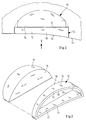
- a combination instrument 10 is shown schematically, that in the usual way e.g. in the area of its front surface 11, which can be covered by a cover slip, or at a distance from the front surface 11 further inside a display panel having.
- the instrument cluster 10 is an aperture 12 upstream, the front surface 13 of a predetermined course 14 follows an instrument panel.
- Aperture 12 is provided, facing away from the instrument cluster 10
- Front surface 13 has such a curvature that the course 14 of the instrument panel in the area of the driver's seat for a left-hand drive vehicle.
- the aperture 12 is in relation to the instrument cluster 10 as independent, detachably attached to the instrument cluster 10 Component 15 formed.
- the attachment of this component 15 on the instrument cluster 10 can in many ways and with Help of different designed common fasteners or mounting options.
- the front surface 11 of the instrument cluster 10 runs inside a plane level, as shown in particular in FIG. 1.
- the Aperture 12 has on the instrument cluster 10 facing Back a flat back surface 16 which e.g. within the flat front surface 11 of the instrument cluster 10 runs, 1 shows, the diaphragm 12 with its rear surface 16 can rest against this flat front surface 11.
- the aperture 12 is superior to the instrument cluster 10 Frame and exists e.g. preferably from one Plastic part, in particular molded plastic part.
- the frame-shaped Aperture 12 has sufficiently thick wall parts 17 and 18, their course, viewed within a the back surface 16 containing plane to the course of the Instrument cluster 10, viewed in the plane front surface 11 containing level is adjusted.
- the entirety of the instrument cluster in FIGS. 1 and 2 is thus in two parts. On the one hand, it consists of the instrument cluster 10, which represents the one component and all components of the instrument, and on the other hand from the interchangeable front frame designed separate component 15, which acts as a front panel and over which the adjustment on the respective course 14 of the instrument panel.
- the interchangeable front frame designed separate component 15 which acts as a front panel and over which the adjustment on the respective course 14 of the instrument panel.
- the front surface 13 of the course 14 of the instrument panel in the area of the driver's seat follows, as with a left-hand drive vehicle is present.
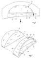
- the aperture 22 differs itself from the aperture 12 of the first embodiment by a different course of their front surface 23, the namely has such a curvature that the Course 24 of the instrument panel in the area of the not shown Driver's seat in a right-hand drive Vehicle follows. This is particularly evident from the top view in 3 can be seen.
- the aperture 22 has the aperture 22 on its plane Front surface 11 of the instrument cluster 10 facing the rear a flat rear surface 26.
- the panel 12 according to FIG. 1 comes and 2 for use, while in such a vehicle, the is controlled by the right and in which the driver's seat is on the right, an aperture 22 according to the second embodiment 3 and 4 is used.
- the instrument cluster 10 is always the same. So it can be used for both of the variants explained, whereby these variants simply by choosing the appropriate one Aperture 12 or 22 is taken into account. This will reduce the costs are kept to a minimum as an adaptable component only a corresponding aperture 12 or 22 is necessary, which is particularly inexpensive as a plastic part. From Another advantage is that in the context of logistics and warehousing costs due to the small volume of each Aperture 12 or 22 further costs can be saved.
- the respective aperture 12 or 22 protrudes the peripheral contour of the instrument cluster 10 over. This is however not mandatory. As in Fig. 1 and Fig. 3 only Is indicated by dashed lines, the aperture 12 or 22 can also Complete flush with the instrument cluster 10.
Landscapes
- Engineering & Computer Science (AREA)
- Chemical & Material Sciences (AREA)
- Combustion & Propulsion (AREA)
- Transportation (AREA)
- Mechanical Engineering (AREA)
- Instrument Panels (AREA)
- Indicating Measured Values (AREA)
Abstract
Description
- Fig. 1
- eine schematische Draufsicht eines Kombiinstruments mit vorgeschalteter Blende gemäß einem ersten Ausführungsbeispiel,
- Fig. 2
- eine schematische Ansicht des Kombiinstruments und der Blende in Pfeilrichtung II in Fig. 1 gemäß dem ersten Ausführungsbeispiel, wobei die Blende noch nicht am Kombiinstrument angebracht ist,
- Fig. 3
- eine schematische Draufsicht etwa entsprechend derjenigen in Fig. 1 eines Kombiinstruments mit vorgeschalteter Blende gemäß einem zweiten Ausführungsbeispiel,
- Fig. 4
- eine schematische Ansicht etwa entsprechend derjenigen in Fig. 2 des Kombiinstruments und der Blende in Pfeilrichtung IV in Fig. 3, jedoch bei noch nicht angebrachter Blende.
Claims (5)
- Kombiinstrument mit einem Gehäuseteil, das einen Frontrahmen und eine diesem vorgelagerte Blende aufweist, wobei im Frontrahmen die Instrumenteinrichtungen und eine vordere Abdeckung enthalten sind,
dadurch gekennzeichnet,
daß die Vorderfläche (11) des Frontrahmens innerhalb einer planen Ebene verläuft, daß die Blende (12;22) ein eigenständiges, am Frontrahmen lösbar befestigbares Bauteil (15;25) bildet und eine Vorderfläche (13) aufweist, die einem vorgegebenen Verlauf einer Instrumententafel (14) folgt, und daß die Blende (12;22) auf ihrer dem Frontrahmen zugewandten Rückseite eine innerhalb einer planen Ebene verlaufende Rückfläche (16;26) aufweist, die zumindest im wesentlichen parallel zur Vorderfläche (11) des Frontrahmens verläuft. - Kombiinstrument nach Anspruch 1,
dadurch gekennzeichnet,
daß die Blende (12;22) mit ihrer Rückfläche (16;26) an der Vorderfläche (11) des Frontrahmens anliegt oder in Abstand davon verläuft. - Kombiinstrument nach Anspruch 1 oder 2,
dadurch gekennzeichnet,
daß die Blende (12;22) als dem Frontrahmen vorgesetzter Rahmen ausgebildet ist. - Kombiinstrument nach einem der Ansprüche 1 bis 3,
dadurch gekennzeichnet,
daß die Blende (12;22) aus einem Kunststoffteil, insbesondere Kunststofformteil, gebildet ist. - Kombiinstrument nach einem der Ansprüche 1 bis 4,
gekennzeichnet durch
eine Blende (12;22), deren dem Frontrahmen abgewandte Vorderfläche (13;23) einen solchen Verlauf aufweist, der dem Verlauf (14 bzw. 24) der Instrumententafel im jeweiligen Bereich des Fahrzeugführersitzes folgt, insbesondere bei einem linksgesteuerten Fahrzeug dem dortigen Verlauf (14) und bei einem rechtsgesteurten Fahrzeug dem abweichenden anderen Verlauf (24).
Applications Claiming Priority (2)
| Application Number | Priority Date | Filing Date | Title |
|---|---|---|---|
| DE19642834A DE19642834C1 (de) | 1996-10-17 | 1996-10-17 | Kombiinstrument |
| DE19642834 | 1996-10-17 |
Publications (3)
| Publication Number | Publication Date |
|---|---|
| EP0836963A2 true EP0836963A2 (de) | 1998-04-22 |
| EP0836963A3 EP0836963A3 (de) | 1998-05-13 |
| EP0836963B1 EP0836963B1 (de) | 1999-12-01 |
Family
ID=7809002
Family Applications (1)
| Application Number | Title | Priority Date | Filing Date |
|---|---|---|---|
| EP97116767A Expired - Lifetime EP0836963B1 (de) | 1996-10-17 | 1997-09-26 | Kombiinstrument |
Country Status (4)
| Country | Link |
|---|---|
| US (1) | US6109679A (de) |
| EP (1) | EP0836963B1 (de) |
| JP (1) | JPH10148548A (de) |
| DE (2) | DE19642834C1 (de) |
Families Citing this family (7)
| Publication number | Priority date | Publication date | Assignee | Title |
|---|---|---|---|---|
| DE19957867A1 (de) | 1999-12-01 | 2001-06-07 | Volkswagen Ag | Kombi-Instrument für Kraftfahrzeuge |
| DE10105362B4 (de) * | 2001-02-05 | 2008-01-03 | Robert Bosch Gmbh | Gehäuse, insbesondere für eine Anzeigevorrichtung |
| DE102007010381B4 (de) * | 2007-03-03 | 2015-02-05 | Audi Ag | Head-Up-Display für ein Kraftfahrzeug |
| US20090090756A1 (en) * | 2007-10-09 | 2009-04-09 | Gauge Works, Llc | Dashboard gauge display apparatus |
| ES2461368B1 (es) | 2012-11-16 | 2015-03-10 | Seat Sa | Estructura de cierre entre el cuadro de instrumentos y la columna de dirección de un vehículo |
| DE102012223787A1 (de) * | 2012-12-19 | 2014-06-26 | Continental Automotive Gmbh | Kombiinstrument mit einer Blende |
| USD949766S1 (en) * | 2020-02-24 | 2022-04-26 | Lg Electronics Inc. | Interior for vehicles |
Citations (2)
| Publication number | Priority date | Publication date | Assignee | Title |
|---|---|---|---|---|
| DE3346370A1 (de) | 1983-12-22 | 1985-07-11 | Robert Bosch Gmbh, 7000 Stuttgart | Verfahren zur anzeige von informationen, vorzugsweise in einem kraftfahrzeug |
| DE4343201A1 (de) | 1993-12-17 | 1995-06-22 | Vdo Schindling | Anzeigeeinrichtung |
Family Cites Families (18)
| Publication number | Priority date | Publication date | Assignee | Title |
|---|---|---|---|---|
| US2165660A (en) * | 1937-12-20 | 1939-07-11 | Gen Motors Corp | Instrument cluster cabinet |
| US2423597A (en) * | 1942-02-09 | 1947-07-08 | Smith & Sons Ltd S | Instrument panel for motor cars and other vehicles |
| US2771148A (en) * | 1951-09-08 | 1956-11-20 | Daimler Benz Ag | Instrument panel for motor vehicles |
| US2855066A (en) * | 1955-10-25 | 1958-10-07 | Daimler Benz Ag | Instrument panels, especially for motor vehicles |
| US3270831A (en) * | 1960-07-08 | 1966-09-06 | Gen Motors Corp | Dashboard subassembly |
| DE1455678A1 (de) * | 1963-06-27 | 1969-03-13 | Porsche Kg | Armaturenbrett fuer Fahrzeuge,insbesondere Kraftfahrzeuge |
| US3269210A (en) * | 1964-08-28 | 1966-08-30 | Kiekhaefer Corp | Combined steering wheel and instrument panel mounting for boats |
| DE2127686C3 (de) * | 1971-06-04 | 1974-10-03 | Daimler-Benz Ag, 7000 Stuttgart | Armaturenbrett für Kraftfahrzeuge, insbesondere Lastkraftwagen |
| US4392539A (en) * | 1979-12-17 | 1983-07-12 | Honda Giken Kogyo Kabushiki Kaisha | Instrument panel with a yieldable meter casing |
| JPS57164816A (en) * | 1981-04-01 | 1982-10-09 | Nissan Motor Co Ltd | Mounting structure of meter hood |
| IT1145745B (it) * | 1981-11-19 | 1986-11-05 | Foggini E C Srl | Plancia portastrumenti particolarmente per autoveicoli ad elementi modulari componibili |
| JPS594425U (ja) * | 1982-07-01 | 1984-01-12 | トヨタ自動車株式会社 | コンビネ−シヨンメ−タ被覆構造 |
| US4690432A (en) * | 1984-10-24 | 1987-09-01 | Mazda Motor Corporation | Automobile instrument cluster tiltable with a steering column |
| US5067670A (en) * | 1990-08-08 | 1991-11-26 | Michael Radcliffe | Flight training device for aircraft |
| JPH0840114A (ja) * | 1994-08-02 | 1996-02-13 | Daihatsu Motor Co Ltd | 車両用メータ装置 |
| GB9423776D0 (en) * | 1994-11-25 | 1995-01-11 | Acg Deutschland Gmbh | Dashboard assembly |
| USD401201S (en) | 1995-07-05 | 1998-11-17 | Saleen Performance, Inc. | Gauge pod for customized automobile body |
| USD403641S (en) | 1996-07-30 | 1999-01-05 | Mercedes-Benz Ag | Motor vehicle instrument panel |
-
1996
- 1996-10-17 DE DE19642834A patent/DE19642834C1/de not_active Expired - Fee Related
-
1997
- 1997-09-26 EP EP97116767A patent/EP0836963B1/de not_active Expired - Lifetime
- 1997-09-26 DE DE59700791T patent/DE59700791D1/de not_active Expired - Fee Related
- 1997-10-08 JP JP9320227A patent/JPH10148548A/ja active Pending
- 1997-10-17 US US08/953,375 patent/US6109679A/en not_active Expired - Fee Related
Patent Citations (2)
| Publication number | Priority date | Publication date | Assignee | Title |
|---|---|---|---|---|
| DE3346370A1 (de) | 1983-12-22 | 1985-07-11 | Robert Bosch Gmbh, 7000 Stuttgart | Verfahren zur anzeige von informationen, vorzugsweise in einem kraftfahrzeug |
| DE4343201A1 (de) | 1993-12-17 | 1995-06-22 | Vdo Schindling | Anzeigeeinrichtung |
Also Published As
| Publication number | Publication date |
|---|---|
| DE59700791D1 (de) | 2000-01-05 |
| DE19642834C1 (de) | 1997-12-11 |
| US6109679A (en) | 2000-08-29 |
| EP0836963A3 (de) | 1998-05-13 |
| JPH10148548A (ja) | 1998-06-02 |
| EP0836963B1 (de) | 1999-12-01 |
Similar Documents
| Publication | Publication Date | Title |
|---|---|---|
| DE4008896A1 (de) | Motorraumaufbau eines kraftfahrzeuges | |
| DE2646202A1 (de) | Rueckblickspiegel | |
| DE102008029321B4 (de) | Kraftfahrzeugkarosserie- und -verkleidungsanordnung mit komplementären Positionier- und Einstellmerkmalen | |
| DE3046364A1 (de) | "kraftfahrzeugtuer" | |
| DE2937904A1 (de) | Rueckwaertiger karosserieaufbau eines fahrzeugs | |
| DE3519941C1 (de) | Sitzschale fuer einen Sitz in einem Kraftwagen | |
| DE102017101607A1 (de) | Spoileranordnung eines Kraftfahrzeugs | |
| DE19642834C1 (de) | Kombiinstrument | |
| DE4030171A1 (de) | Dichtungsanordnung an verschliessbaren oeffnungen von fahrzeugkarosserien | |
| DE102019120520A1 (de) | Zierleistenanordnung für eine Kraftfahrzeug-Tür | |
| DE2930640C2 (de) | Befestigung für den stirnseitigen Rand der Seitenabschnitte einer äußeren Dachverkleidung eines Fahrzeugs | |
| DE7811383U1 (de) | Rueckstrahler fuer zweiradpedale | |
| DE4204053A1 (de) | Zubehoereinheit fuer einen fahrzeugspiegel | |
| DE8009110U1 (de) | Armlehne fuer einen fahrzeugsitz | |
| DE2253360A1 (de) | Einstueckiges kunststoff-scharnier | |
| DE69510517T2 (de) | Universelle Kennzeichenschild-Halterung | |
| DE19930059A1 (de) | Instrumententafel eines Kraftfahrzeugs mit einem Handschuhkasten | |
| DE69302177T2 (de) | Starr abgestützte bremsvorrichtung | |
| DE19616180B4 (de) | Aufbau eines Autofensters | |
| DE2746723C2 (de) | Gelenkomnibus | |
| DE3236751A1 (de) | Fahrzeug-karosserie | |
| DE20108148U1 (de) | Blinker für Kraftfahrzeuge | |
| DE8704437U1 (de) | Leuchtschildkasten | |
| DE19536943A1 (de) | Halterungsanordnung an Zentralplatten von Installationsgeräte-Abdeckprogrammen | |
| DE1680205A1 (de) | Heckaufsatz einer Fahrgastraumabdeckung von Kraftfahrzeugen |
Legal Events
| Date | Code | Title | Description |
|---|---|---|---|
| PUAI | Public reference made under article 153(3) epc to a published international application that has entered the european phase |
Free format text: ORIGINAL CODE: 0009012 |
|
| PUAL | Search report despatched |
Free format text: ORIGINAL CODE: 0009013 |
|
| AK | Designated contracting states |
Kind code of ref document: A2 Designated state(s): DE FR GB IT |
|
| AX | Request for extension of the european patent |
Free format text: AL;LT;LV;RO;SI |
|
| AK | Designated contracting states |
Kind code of ref document: A3 Designated state(s): AT BE CH DE DK ES FI FR GB GR IE IT LI LU MC NL PT SE |
|
| AX | Request for extension of the european patent |
Free format text: AL;LT;LV;RO;SI |
|
| 17P | Request for examination filed |
Effective date: 19980422 |
|
| 17Q | First examination report despatched |
Effective date: 19980630 |
|
| AKX | Designation fees paid |
Free format text: DE FR GB IT |
|
| RBV | Designated contracting states (corrected) |
Designated state(s): DE FR GB IT |
|
| GRAG | Despatch of communication of intention to grant |
Free format text: ORIGINAL CODE: EPIDOS AGRA |
|
| GRAG | Despatch of communication of intention to grant |
Free format text: ORIGINAL CODE: EPIDOS AGRA |
|
| GRAH | Despatch of communication of intention to grant a patent |
Free format text: ORIGINAL CODE: EPIDOS IGRA |
|
| RAP1 | Party data changed (applicant data changed or rights of an application transferred) |
Owner name: DAIMLERCHRYSLER AG |
|
| GRAH | Despatch of communication of intention to grant a patent |
Free format text: ORIGINAL CODE: EPIDOS IGRA |
|
| ITF | It: translation for a ep patent filed | ||
| GRAA | (expected) grant |
Free format text: ORIGINAL CODE: 0009210 |
|
| AK | Designated contracting states |
Kind code of ref document: B1 Designated state(s): DE FR GB IT |
|
| REF | Corresponds to: |
Ref document number: 59700791 Country of ref document: DE Date of ref document: 20000105 |
|
| GBT | Gb: translation of ep patent filed (gb section 77(6)(a)/1977) |
Effective date: 19991221 |
|
| ET | Fr: translation filed | ||
| PLBE | No opposition filed within time limit |
Free format text: ORIGINAL CODE: 0009261 |
|
| STAA | Information on the status of an ep patent application or granted ep patent |
Free format text: STATUS: NO OPPOSITION FILED WITHIN TIME LIMIT |
|
| 26N | No opposition filed | ||
| REG | Reference to a national code |
Ref country code: GB Ref legal event code: IF02 |
|
| PGFP | Annual fee paid to national office [announced via postgrant information from national office to epo] |
Ref country code: GB Payment date: 20060921 Year of fee payment: 10 |
|
| PGFP | Annual fee paid to national office [announced via postgrant information from national office to epo] |
Ref country code: FR Payment date: 20060922 Year of fee payment: 10 |
|
| PGFP | Annual fee paid to national office [announced via postgrant information from national office to epo] |
Ref country code: DE Payment date: 20060926 Year of fee payment: 10 |
|
| PGFP | Annual fee paid to national office [announced via postgrant information from national office to epo] |
Ref country code: IT Payment date: 20060930 Year of fee payment: 10 |
|
| GBPC | Gb: european patent ceased through non-payment of renewal fee |
Effective date: 20070926 |
|
| PG25 | Lapsed in a contracting state [announced via postgrant information from national office to epo] |
Ref country code: DE Free format text: LAPSE BECAUSE OF NON-PAYMENT OF DUE FEES Effective date: 20080401 |
|
| REG | Reference to a national code |
Ref country code: FR Ref legal event code: ST Effective date: 20080531 |
|
| PG25 | Lapsed in a contracting state [announced via postgrant information from national office to epo] |
Ref country code: FR Free format text: LAPSE BECAUSE OF NON-PAYMENT OF DUE FEES Effective date: 20071001 |
|
| PG25 | Lapsed in a contracting state [announced via postgrant information from national office to epo] |
Ref country code: GB Free format text: LAPSE BECAUSE OF NON-PAYMENT OF DUE FEES Effective date: 20070926 |
|
| PG25 | Lapsed in a contracting state [announced via postgrant information from national office to epo] |
Ref country code: IT Free format text: LAPSE BECAUSE OF NON-PAYMENT OF DUE FEES Effective date: 20070926 |