EP0836989A2 - Seitenleitwerkstruktur für ein Flugzeug - Google Patents
Seitenleitwerkstruktur für ein Flugzeug Download PDFInfo
- Publication number
- EP0836989A2 EP0836989A2 EP97117214A EP97117214A EP0836989A2 EP 0836989 A2 EP0836989 A2 EP 0836989A2 EP 97117214 A EP97117214 A EP 97117214A EP 97117214 A EP97117214 A EP 97117214A EP 0836989 A2 EP0836989 A2 EP 0836989A2
- Authority
- EP
- European Patent Office
- Prior art keywords
- air
- vertical tail
- vertical
- nose
- structure according
- Prior art date
- Legal status (The legal status is an assumption and is not a legal conclusion. Google has not performed a legal analysis and makes no representation as to the accuracy of the status listed.)
- Granted
Links
- 239000003381 stabilizer Substances 0.000 title claims description 33
- 238000009826 distribution Methods 0.000 claims abstract description 9
- 239000002131 composite material Substances 0.000 claims description 6
- 230000007704 transition Effects 0.000 claims description 6
- 238000009825 accumulation Methods 0.000 claims description 4
- 238000011144 upstream manufacturing Methods 0.000 claims description 4
- 238000010438 heat treatment Methods 0.000 claims description 3
- 230000010354 integration Effects 0.000 claims description 3
- 238000005538 encapsulation Methods 0.000 claims 1
- 239000011796 hollow space material Substances 0.000 claims 1
- 230000000087 stabilizing effect Effects 0.000 claims 1
- 230000001105 regulatory effect Effects 0.000 abstract description 4
- 210000001331 nose Anatomy 0.000 description 27
- 238000000605 extraction Methods 0.000 description 9
- 238000000926 separation method Methods 0.000 description 4
- 238000005516 engineering process Methods 0.000 description 3
- 238000005259 measurement Methods 0.000 description 3
- 230000002441 reversible effect Effects 0.000 description 3
- RTAQQCXQSZGOHL-UHFFFAOYSA-N Titanium Chemical compound [Ti] RTAQQCXQSZGOHL-UHFFFAOYSA-N 0.000 description 2
- 230000000903 blocking effect Effects 0.000 description 2
- 230000001364 causal effect Effects 0.000 description 2
- 238000010079 rubber tapping Methods 0.000 description 2
- 239000010936 titanium Substances 0.000 description 2
- 229910052719 titanium Inorganic materials 0.000 description 2
- OKTJSMMVPCPJKN-UHFFFAOYSA-N Carbon Chemical compound [C] OKTJSMMVPCPJKN-UHFFFAOYSA-N 0.000 description 1
- 239000004593 Epoxy Substances 0.000 description 1
- 229920000784 Nomex Polymers 0.000 description 1
- 230000004913 activation Effects 0.000 description 1
- 230000005540 biological transmission Effects 0.000 description 1
- 238000010276 construction Methods 0.000 description 1
- 238000001816 cooling Methods 0.000 description 1
- 230000006378 damage Effects 0.000 description 1
- 230000003111 delayed effect Effects 0.000 description 1
- 239000011152 fibreglass Substances 0.000 description 1
- 238000007710 freezing Methods 0.000 description 1
- 230000008014 freezing Effects 0.000 description 1
- 239000000446 fuel Substances 0.000 description 1
- 229910002804 graphite Inorganic materials 0.000 description 1
- 239000010439 graphite Substances 0.000 description 1
- 230000006872 improvement Effects 0.000 description 1
- 230000002427 irreversible effect Effects 0.000 description 1
- 238000004519 manufacturing process Methods 0.000 description 1
- 229910052751 metal Inorganic materials 0.000 description 1
- 239000002184 metal Substances 0.000 description 1
- 238000000034 method Methods 0.000 description 1
- 239000004763 nomex Substances 0.000 description 1
- 238000005457 optimization Methods 0.000 description 1
- 239000002245 particle Substances 0.000 description 1
- 230000035515 penetration Effects 0.000 description 1
- 230000008569 process Effects 0.000 description 1
- 230000001953 sensory effect Effects 0.000 description 1
- 238000010257 thawing Methods 0.000 description 1
- 230000007306 turnover Effects 0.000 description 1
- XLYOFNOQVPJJNP-UHFFFAOYSA-N water Substances O XLYOFNOQVPJJNP-UHFFFAOYSA-N 0.000 description 1
Images

Classifications
-
- B—PERFORMING OPERATIONS; TRANSPORTING
- B64—AIRCRAFT; AVIATION; COSMONAUTICS
- B64C—AEROPLANES; HELICOPTERS
- B64C21/00—Influencing air flow over aircraft surfaces by affecting boundary layer flow
- B64C21/02—Influencing air flow over aircraft surfaces by affecting boundary layer flow by use of slot, ducts, porous areas or the like
- B64C21/06—Influencing air flow over aircraft surfaces by affecting boundary layer flow by use of slot, ducts, porous areas or the like for sucking
-
- B—PERFORMING OPERATIONS; TRANSPORTING
- B64—AIRCRAFT; AVIATION; COSMONAUTICS
- B64C—AEROPLANES; HELICOPTERS
- B64C2230/00—Boundary layer controls
- B64C2230/04—Boundary layer controls by actively generating fluid flow
-
- B—PERFORMING OPERATIONS; TRANSPORTING
- B64—AIRCRAFT; AVIATION; COSMONAUTICS
- B64C—AEROPLANES; HELICOPTERS
- B64C2230/00—Boundary layer controls
- B64C2230/06—Boundary layer controls by explicitly adjusting fluid flow, e.g. by using valves, variable aperture or slot areas, variable pump action or variable fluid pressure
-
- B—PERFORMING OPERATIONS; TRANSPORTING
- B64—AIRCRAFT; AVIATION; COSMONAUTICS
- B64C—AEROPLANES; HELICOPTERS
- B64C2230/00—Boundary layer controls
- B64C2230/22—Boundary layer controls by using a surface having multiple apertures of relatively small openings other than slots
-
- Y—GENERAL TAGGING OF NEW TECHNOLOGICAL DEVELOPMENTS; GENERAL TAGGING OF CROSS-SECTIONAL TECHNOLOGIES SPANNING OVER SEVERAL SECTIONS OF THE IPC; TECHNICAL SUBJECTS COVERED BY FORMER USPC CROSS-REFERENCE ART COLLECTIONS [XRACs] AND DIGESTS
- Y02—TECHNOLOGIES OR APPLICATIONS FOR MITIGATION OR ADAPTATION AGAINST CLIMATE CHANGE
- Y02T—CLIMATE CHANGE MITIGATION TECHNOLOGIES RELATED TO TRANSPORTATION
- Y02T50/00—Aeronautics or air transport
- Y02T50/10—Drag reduction
Definitions
- the invention relates to a vertical stabilizer structure for an aircraft according to the Preamble of Claim 1. It is primarily used to extract the disturbed boundary layer operated on the vertical tail in order to stabilize the laminar flow there and / or to rule out flow separation.
- EP 0 436 243 B1 presents an aircraft structure on its surface the disturbed boundary layer is affected.
- the aircraft structure in particular is sucked off on the surface of an aircraft wing, has several wingspan extending chamber subdivisions, which a multi-layer structure perforated outer skin rests.
- a compressor unit which with the chamber structure, which is in the front (inflow) area of the wing (leading edge of the wing and above and below adjacent areas of the wing) stands, one initiates an air flow on the one hand to the front (partial) areas of the To de-ice the outer skin, or on the other hand, create a chamber vacuum in order to To operate extraction at these sections.
- the aircraft (wing) structure does not provide for any adjustment of the amount of air extracted or blown out. Thereafter, a suction or blow-out distribution of the air in or on the aircraft wing is realized only with a fixed setting, so that the air distribution state would not be adaptable to the prevailing causal conditions for influencing the boundary layers. It is mentioned that in the suction mode, a flow through the non-suctioned chambers - due to the pressure gradient over the chamber in question [that is, air flows into the chamber (s) in the area of higher external pressure and flows out of the chamber (s) in the area of low external pressure (n) air out] - occurs, which is why the risk of flow separation could never be excluded.
- the invention is therefore based on the object of a generic vertical tail structure to design in such a way that the controlled extraction of the disturbed Boundary layer is reached at the vertical tail and also icing of the vertical tail nose area can be prevented.
- Appropriate measures should be taken laminar surface flow can be realized on the vertical tail, which makes the Aircraft drag is reduced, fuel savings are achieved and one significant improvement in the economy of a passenger aircraft is.
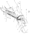
- the structure of the vertical tail structure for the vertical tail 1 is one Passenger plane shown.
- the vertical tail 1 basically consists of the Vertical tail support structure 2, the front end of the front spar 23 is a vertical tail nose part 3 is firmly seated and the rudder 21 on the rear of the rear spar 24 is subordinate.
- the defined arrangement of the vertical tail can also be seen 1 and one of the two vertical fins 20 of the horizontal stabilizer on the fuselage tail of the passenger plane, the pipelines associated with the vertical tail structure and indicated means are also shown.
- the vertical tail part 3 consists of a (within the span of the vertical tail 1 extending) nose profile edge 4 there.
- the latter has an inward arch parabolic approximate shape and is divided by chambers 41.
- the chambers 41 have a closed channel course in the span of the vertical tail 1 and result in a chamber substructure.
- This chamber substructure (suction chambers) consists of folded metal sheets that subdivide the vertical tail structure form.
- the outer surface 42 of the nose profile edge 4 is perforated.
- a perforated surface element 43 which conforms to the shape of the nose profile edge, is fastened on it 4 adapts.
- the surface element 43 functionally provides a support and support structure represents that together with the nose profile edge 4 forms a composite structure. Between the front spar 23 of the vertical tail support structure 2 and the spanwise extending inner surface of the nose profile edge 4 clamps (not shown) cavity on which the vertical tail support structure 2 delimits. Are there at least one end of the chambers 41 and one end of the cavity are closed.
- a perforated layer 46 is also attached, the Front edge area 31 of the vertical tail part 3 is covered.
- This layer 46 represents a perforated sheet, which with suitable measures on the surface of the Surface element 43 is attached.
- the perforation of the outer sheet is laser-drilled Realized holes, the surface (pattern) of which (described later) controlled suction of the disturbed boundary layer 6 (with that of the vertical tail structure allocated funds).
- the rudder nose part 3 in two parts.
- This embodiment is indicated in FIG. 1 with the reference to the position of an upper and a lower vertical tail part 32, 33, which are arranged one after the other in spans. Since the division into two parts (for technological reasons) is transferred to the vertical stabilizer support structure 2 located below the vertical stabilizer nose part 3, the upper end face of the upper vertical stabilizer nose part 33 (and the area below it that is directed towards the vertical stabilizer tip) is referred to the span of the vertical stabilizer 1 Surface of the nose profile edge 4) be perforated. In this embodiment, the layer 46, which is applied to this part of the outer surface, will only be provided with a perforation in this area.
- the upper and / or lower vertical tail nose part 32, 33 is in the accumulation line area equipped with suction ports (tappings), after which the surface suctioned and convey air into the chamber substructure from the chambers 41. Since the suction chambers have a small (small) volume (shape), the suction ports should have a uniform suction distribution on their surface guarantee.
- the vertical tail support structure 2 generally has a vertical tail box embodies the manufacturing technology related to the span of the vertical tail 1 is carried out in two parts. After that, there are two spans in a row arranged tail fin parts, an upper and lower part of the nose box, in their integration the vertical tail box.
- the top is the front Outer surface of an upper tail fin part directed towards the tail tip.
- the lower front outer surface of a lower vertical tail box part is directed to the empennage root.
- the front inner surfaces of both vertical tail nasal box parts are an interface of the (two) divided vertical tail box to each other.
- the pipes 5 are provided with a valve control unit 7.
- the latter comprises a plurality of air suction control valves 71 which are inserted individually into each pipeline (5) assigned to them.
- the valve control unit 7 regulates a surface-related, defined suction distribution at the leading edge region 31 of the vertical tail part 3.
- the pipes 5 open into the air collecting container 16, upstream of which the air suction control valves 71, which are installed near each pipe outlet.
- a control device (not shown), which is placed at a specific location inside the fuselage stern and which consists of at least one controller, controls the air suction control valves 71 separately via signal lines on the basis of related sensor signals.
- the compressor unit 8 can be started up load-free because, for example, by blocking the two control valves of the pipeline valve interface 14, 15, which are connected upstream and downstream, the air flow supply and discharge are interrupted.
- the compressor unit 8 consists (generally) of a multi-stage suction fan, controlled in correlation with the amount of air to be extracted (controlled by the aforementioned Control device) can be switched on or off.
- the exhaust fan stages cannot be switched off.
- the angle of attack of the fan blades of the suction fan can be changed in correlation to the amount of air to be extracted.
- the speed control of the suction fan can be done continuously or in stages.
- the compressor unit 8 is designed in such a way that it is used as a suction device a three-stage suction fan (fan) used, the fan blades are not controllable, whereby it is therefore without speed control (without switchable or switchable Step control of the suction fan) works.
- the cross section of the cavity of the (inward closed) chamber 41 falls in particular in the accumulation line area of the vertical tail nose part 3 or for example (provided) upper rudder nose part 33 very small out. Therefore, the chambers 41 are additional tap lines (not shown) (Pipes) associated with the valve control unit 7. In order to is distributed across the vertical tail 1 (or the upper vertical tail nose part 33) - additionally extracted air from the chambers 41, so that a relatively even, wide-spread suction distribution on the (upper) vertical tail section 3 sets.
- the dispensing lines - later suction lines 5 - are with the air collection container 16 connected, which via the pipeline (bridge) 9 of the compressor unit 8 additionally Feed extracted air from the chambers 41.
- the tappings (tap lines) go later in the suction line 5 of the chamber 41 associated with them.
- the Sensors determine the total mass air flow discharged by the compressor unit 8 . They are connected to the control device via signal lines and convert the actually flowing total mass flow of the exhaust air into the corresponding one Signals around. The control device then compares these signals supplied to it a saved preset. On the basis of the comparison there is then a by-pass interface 11, which (based on the measurement comparison) the supply of the external air let in through the by-pass pipe connection 14 regulates and keeps the operating point of the compressor unit 8 stable.
- the by-pass valve interface 11 itself is realized by means of a by-pass control valve.
- the air outlet 13 itself is definitely installed at a point in the fuselage on which low external pressure and low Cp value. As a result of the low State values can be the exhaust air passing through the pipe outlet 12, that of the compressor unit 8 is discharged, flow out almost automatically.
- the bleed air pipe connection 17 is the air collection container 16 branched, which is generally connected to the aircraft compressed air system.
- an icing of the Surface of the tail unit 1 at least the leading edge region 31 of the vertical tail part 3
- a bleed air pipe connection 18 on which a bleed air shut-off valve sits.
- the bleed air pipe connection 17 with warm and under pressure Bleed air of the engines and / or the auxiliary gas turbine supplied.
- the vertical tail structure is supplemented with a pivotable camera 19, the Optics on the vertical tail section 3 and / or on the vertical tail support structure 2 is directed.
- the camera 19 designed as an IR camera is used to Behavior of the boundary layer 6 disturbed by controlled suction during its Influencing can be observed in the cruise of a passenger plane.
- IR infrared technology provided
- a wake rake 22 is pivotally attached, which detects the air pressure in the wake region of the rudder 21 at several points in order to measure the influence of the extracted rudder unit 1 on the air flow.
- the trailing rake 22 itself is constructed to be vertically displaceable (traversable) at the vertical free end of the rudder 21 and is mounted so that it can move in a defined area.
- the function of the (suction) vertical stabilizer structure is described in more detail described. As intended - it should be used to extract the disturbed boundary layer or at least the microturbulence with the vertical tail structure in Area of predominant laminar flow (primary) the laminar flow at the vertical tail 1 can be stabilized. Furthermore, the laminar barrel length of the laminar Flow on the side surfaces of the vertical tail 1 - to near the rudder side surface of the rudder 21 - to be expanded to the maximum possible To achieve resistance savings, but only until just before the rudder 21 to the Not to affect rudder effectiveness (due to the risk of flow separation). There must be turbulent flow.
- the surface of the above-mentioned vertical stabilizer noses is therefore provided with a perforated outer sheet made of titanium, through whose (laser-drilled) holes the controlled extraction of the disturbed boundary layer (in the plane's flight) will take place.
- a perforated outer sheet made of titanium, through whose (laser-drilled) holes the controlled extraction of the disturbed boundary layer (in the plane's flight) will take place.
- Below the outer sheet is the supporting / supporting structure of the surface element 43, which simultaneously forms inwardly directed closed chambers 41 (as a chamber structure).
- the fan (the suction device) of the (three-stage) blower generates the vacuum required for suction, which simultaneously initiates the mass flow rate of the boundary layer air to be extracted through the vertical tail nose part 3, the air (extracted at the leading edge area 31) becomes spanned the vertical tail 1 and then passed through the pipes 5 connected to the chamber structure into the air collection container 16.
- the bleed-air shut-off valve of the bleed-air pipe connection 18 or the control valve of the bleed air control valve interface of the bleed air pipe connection 17 are in the closed state during the suction mode.
- the shut-off valves of the first and second pipeline valve interfaces 14, 15 are open during the suction mode, which is why the air drawn off in the span direction is passed unhindered to the compressor unit 8 (into the interior of the fuselage).
- the suction air flow per chamber 41 is controlled by the air suction control valves 71, based on the sensor signals [of the pressure and temperature and flow sensors on the inner wall (near the outlet opening into the air collection container 16) of the relevant pipeline 5] in of the measuring section, the suction air flow is determined by sensor and compared with a specification by the control unit (located inside the fuselage).
- the corresponding valve position of the air suction control valve 71 in question is determined by the control unit and accordingly adjusted on the air suction control valve 71 in question from the comparison of the actual state determined by sensors with the stored specification.
- the pipes 5 in front of the compressor unit 8) are brought together in the air collecting container 16. Since the blower unit is a turbomachine, the operating point of the compressor unit 8 must be (almost) stabilized.
- the by-pass interface 11 regulates (based on the result of the comparison) the supply of the external air drawn in, which is admitted through the by-pass pipe connection 14, in such a way that the operating point of the compressor unit 8 remains stable.
- two separate control loops are set up, which react relatively quickly and, by summing the extracted (supplied) individual air flows per (suction) pipeline 5 plus the by-pass (external) air flow, avoid error transmission.
- the extracted air (the boundary layer 6) is blown out in a controlled manner through the air outlet 13 (here through a window let into the fuselage).
- a location of the lowest possible pressure (lowest Cp value) outside the fuselage is ideal for the location of the air outlet 13, since the required power of the extraction fan (extraction device) can be reduced as a result of this - due to the automatic flow of the exhaust air.
- Activation of the anti-icing protection requires that the two shut-off valves the first and second pipeline valve interfaces 14, 15 and the by-pass valve the by-pass valve interface 11 are in the closed state.
- the controllable bleed air control valve interface - passes through the bleed air pipe connection 17 warm and under pressure Bleed air of the engines or the auxiliary gas turbine, the bleed air via the air collection container 16 flows into the individual pipes 5, which after passing the Chamber structure and the downstream perforations of the vertical tail part 3 by the hole pattern of layer 46 (the outer sheet) or by the suction lugs flows.
- valve control unit 7 depending on the determined Condition (with respect to the current pressure, temperature, flow rate ratios regulates the bleed air supply air at layer 46) by means of suitable elements (sensors) and at the same time sets signals for the controlled regulation of the bleed air shut-off valve.
- valve control unit 7 With the control unit inside the fuselage, which is connected to the valve control unit 7 would be a target / actual comparison (current state compared to a specification) feasible, which results in corresponding valve positions for controlled bleed air supply let settle.
- transition position transition from laminar to turbulent
- Infrared camera installed in a fin 20.
- This IR camera looks with her Optics on the vertical tail box, on which heating mats are applied, which one Set and maintain the reference temperature.
- surface temperature a there is a surface temperature a. The turnover situation can thus be seen from the temperature image.
- Each individual suction area (each chamber 41) is controlled individually, that is the suction quantity per chamber can be individually adjusted (adjustable) via control valves.
- the vertical tail structure has two separate control loops (control of the by-pass interface 11 via sensors in the air outlet 13 and regulation of the individual flow rates in the chambers 41 via the valve control unit 7), the advantages of which are described above are.
- the suction fan (suction device) of the compressor unit 8 is independent of the individual flow rates in the chamber structure, as these are by-pass be compensated.
Landscapes
- Engineering & Computer Science (AREA)
- Chemical & Material Sciences (AREA)
- Combustion & Propulsion (AREA)
- Aviation & Aerospace Engineering (AREA)
- Structures Of Non-Positive Displacement Pumps (AREA)
- Vehicle Body Suspensions (AREA)
- Packages (AREA)
- Ventilation (AREA)
Abstract
Description
Danach sah ein Vorschlag von " Lockheed " die Sandwich-Konstruktion eines Flügelstücks aus Nomex-Waben mit einer Graphit-Epoxy-Haut vor, über der eine dünne Haut liegt. In dieser äußeren Haut sind Längsschlitze eingeritzt, die quer zur Strömungsrichtung verlaufen. Durch die Schlitze, die auf der Ober- und Unterseite der Tragfläche, jedoch nur im Nasenbereich verlaufen, wird - durch Erzeugung eines Unterdruckes in den Kammern der Tragfläche - die Luft in das Flächeninnere abgesaugt. Die angesaugte Luftmenge kann den Außenbedingungen entsprechend über eine Kontrolleinheit geregelt werden.
Beide Lösungsvorschläge beziehen sich auf ein Tragflächenkonzept, mit dem durch Schlitzung oder Löcherung der Tragflächenoberfläche eine Absaugung der die Tragfläche umströmenden Grenzschicht ober- und / oder unterhalb und nur im Nasenbereich betrieben werden kann. Detailierte Lösungsansätze, die in Funktion einer Anordnung die Absaugung einer Tragflügeloberfläche mit geeigneten Mitteln beschreiben, werden nicht offenbart. Es werden auch keine Anregungen vermittelt, mittels derer man zu einer Lösung für eine Seitenleitwerksstruktur gelangen würde, mit der sich die gestörte Grenzschicht an einem Seitenleitwerk kontrolliert laminisieren läßt und ein Vereisen der Seitenleitwerksoberfläche verhindert wird.
2Das Lösungskonzept berücksichtigt die Ableitung verschiedener Abluftströme nach außerhalb des Flugzeuges, wobei sich die Ableitung der Turbinenabluft und der abgesaugten Luft nur mit hohem (konstruktiven und technologischen) Aufwand betreiben läßt. Erfolgt kein Absaugen, dann läßt sich das (teilweise) Einströmen der Außenluft durch das Tragprofil (die Außenhaut) nach innerhalb in die Kammern kaum vermeiden, weshalb unter anderem auch an den Kammerwänden (bestimmter Kammern) zusätzlich die erwähnten Rückschlagventile installiert sind, um das Eindringen dieser Außenluft in den nicht abgesaugten Kammernteil auszuschließen.
- Fig. 1
- eine Seitenleitwerksstruktur mit Seitenruder einschließlich Darstellung mehrerer Rohrleitungsverbindungen und Mittel zur Absaugung bzw. Ausblasung und zur meßtechnischen Kontrolle;
- Fig. 2
- eine Querschnittsdarstellung des Nasenkastens.
Bei dieser Ausführung wird dann die Schicht 46, welche auf diesem Teil der Außenfläche aufgebracht ist, nur in diesem Bereich mit einer Perforation versehen sein. Deswegen wird nur ein Teilbereich der Verbundstruktur des Seitenleitwerksnasenteiles 3 perforiert ausgeführt, auf dem die perforierte Schicht (46) aufgebracht ist. Dabei bleibt nicht ausgeschlossen, daß nur ein streifenförmiger Bereich der Verbundstruktur perforiert ausgebildet ist, dem die perforierte Schicht 4 aufliegt.
Die zur Leitwerkswurzel gerichtete untere Außenfläche wird oftmals keine Perforierung aufweisen, so daß der Verbindungsübergang der Rohrleitungen 5 dann zum nicht perforierten Nasenbereich der Seitenleitwerksstruktur erfolgen wird.
Eine (nicht gezeigte) Kontrolleinrichtung, die man an bestimmter Stelle im Inneren des Rumpfhecks platziert und die wenigstens aus einem Kontroller (Regler) besteht, steuert über Signalleitungen die Luftabsaug-Regelventile 71 auf der Basis bezogener Sensorsignale separat an. Auf der Rohrleitung(sbrücke) 9 sitzt jeweils eine Rohrleitungs-Ventilschnittstelle 14, 15, die der Kompressoreinheit 8 vor- und / oder nachgeordnet ist. Mit deren Unterstützung läßt sich die Kompressoreinheit 8 lastfrei hochfahren, weil beispielsweise durch Sperrung der beiden Regelventile der Rohrleitungs-Ventilschnittstelle 14, 15, die unmittelbar vor- und nachgeschalten sind, die Luftstromzu- und abfuhr unterbrochen wird.
Auf der Seitenleitwerk-Tragstruktur 2 liegt wenigstens ein (nicht gezeigtes) Flächenheizelement, das eine konstante Oberflächentemperatur zur Transitionslagenbestimmung mit Hilfe der Kamera 19 realisiert.
Der Nachlaufrechen 22 selbst ist am vertikalen freien Ende des Seitenruders 21 vertikal verschiebbar (traversierbar) aufgebaut und in einem definierten Bereich diesem gegenüber beweglich angebaut.
Infolge dessen, daß mit dem Lüfter (dem Absaugedevice) des (dreistufigen) Gebläses der nötige Unterdruck zur Absaugung erzeugt wird, der gleichzeitig den Massendurchsatz der abzusaugenden Grenzschichtluft durch das (den betreffenden) Seitenleitwerksnasenteil 3 initiiert, wird die (am Vorderkantenbereich 31 abgesaugte) Luft spannweitig dem Seitenleitwerk 1 abgeführt und über die mit der Kammerstruktur verbundenen Rohrleitungen 5 danach in den Luftsammelbehälter 16 geleitet. Bei diesem Vorgang befinden sich das Bleed-Air-Sperrventil der Bleed-Air-Rohrleitungsverbindung 18 bzw. das Regelventil der Zapfluft-Regelventilschnittstelle der Zapfluft-Rohrleitungsverbindung 17 - während des Absaugemode - im geschlossenen Zustand. Die Shut-Off-Ventile der ersten und zweiten Rohrleitungs-Ventilschnittstelle 14, 15 sind - während des Absaugemode - geöffnet, weshalb die in Spannweitenrichtung abgesaugte Luft ungehindert zur Kompressoreinheit 8 (in das Rumpfinnere) geleitet wird. Der Absaugluftstrom je Kammer 41 wird dabei durch die Luftabsaug-Regelventile 71 geregelt, wobei auf Basis der Sensorsignale [des Druck- und des Temperatur- und des Durchflußsensors an der Innenwandung (nahe dem in den Luftsammelbehälter 16 mündenden Ausgang) der betreffenden Rohrleitung 5] in der Meßstrecke der Absaugeluftstrom sensorisch ermittelt und durch die (im Rumpfinneren sitzende) Kontrolleinheit mit einer Vorgabe verglichen wird. Aus dem Vergleich des sensorisch ermittelten tatsächlichen Zustandes mit der gespeicherten Vorgabe wird im Ergebnis die entsprechende Ventilposition des betreffenden Luftabsaug-Regelventils 71 durch die Kontrolleinheit bestimmt und dementsprechend am betreffenden Luftabsaug-Regelventils 71 eingeregelt. Um die Anzahl der Gebläseeinheiten (Absaugedevice) zu reduzieren, werden die Rohrleitungen 5 (vor der Kompressoreinheit 8) in dem Luftsammelbehälter 16 zusammengeführt. Da die Gebläseeinheit eine Strömungsmaschine darstellt, muß der Betriebspunkt der Kompressoreinheit 8 (nahezu) stabilisiert werden.
Durch die Regelung der Fremdluftzufuhr mittels dem By-Pass-Ventil, das den Betriebspunkt des Absaugegebläses (des Absaugedevices) der Kompressoreinheit 8 stabilisiert, wird demnach verhindert, daß dem Absaugegebläse zuwenig Luft zugeführt wird, wodurch mit dieser Maßnahme ein Strömungsabriß an den Leitschaufeln der Strömungsmaschine verhindert wird, was sonst zu einer Zerstörung derselben führen könnte.
Es wird angemerkt, daß durch die By-Pass-Rohrleitungsverbindung 10 (bei geöffnetem By-pass-Regelventil bzw. geöffneter By-Pass-Ventilschnittstelle 11) dann ein kontrollierter Luftstrom der Kompressoreinheit 8 einströmt, so daß der die Kompressoreinheit 8 passierende Gesamtluftstrom sich aus der Summe: Absaugleitungs-Luftstrom plus By-Pass-Luftstrom bildet. Mit dem über die By-Pass-Rohrleitung eingelassenen Fremdluftstrom wird der durch die Kompressoreinheit 8 geleitete Gesamtluftstrom stabil gehalten. Die By-Pass-Schnittstelle 11 regelt (auf Basis des Ergebnisses des Vergleiches) die Zufuhr der bezogenen Fremdluft, die durch die By-Pass-Rohrleitungsverbindung 14 eingelassenen wird, derart, daß sich der Betriebspunkt der Kompressoreinheit 8 stabil hält. Dadurch werden zwei getrennte Regelkreise eingerichtet, die relativ schnell reagieren und durch die Summierung der abgesaugten (zugeleiteten) Einzelluftströme pro (Absaug-) Rohrleitung 5 plus dem By-Pass-(Fremd-)Luftstrom somit eine Fehlerübertragung vermeiden.
Die abgesaugte Luft (der Grenzschicht 6) wird - nach ihrem Passieren durch die Kompressoreinheit 8 - durch den Luftauslaß 13 (hier durch ein im Flugzeugrumpf eingelassenes Fenster) kontrolliert ausgeblasen. Ideal für den Ort des Luftauslasses 13 ist eine Stelle möglichst niedrigen Druckes (niedrigsten Cp-Wertes) außerhalb des Flugzeugrumpfes, da hierdurch die erforderliche Leistung des Absaugegebläses (Absaugedevices) - infolge selbsttätigem Strömen der Abluft - reduziert werden kann.
Andererseits läßt sich - bei Abschaltung des Absaugemode - das Ausblasen von warmer Luft an der Nasenoberfläche erreichen, wobei sich mit geeigneten (vorbeschriebenen) Maßnahmen eine bestimmte Ausblasemenge definiert einstellen läßt (Outflow Requierements), wodurch andererseits für den Ausblasefall eine maximale Luftmenge zur Verfügung stehen würde.
Claims (23)
- Seitenleitwerksstruktur für ein Flugzeug, bei der einer Seitenleitwerk-Tragstruktur stirnseitig ein Seitenleitwerksnasenteil fest aufsitzt, dessen nach innen gekrümmter und parabelgenähert geformter Nasenprofilrand durchlässig aufgebaut und durch Kammern, die in der Spannweite eines Seitenleitwerkes einen geschlossenen Kanalverlauf besitzen, unterteilt ist, bei der die Außenfläche des Nasenprofilrandes perforiert ausgeführt ist, der ein perforiertes Flächenelement, das der Form des Nasenprofilrandes angepaßt ist, befestigt aufliegt, wobei der Nasenprofilrand mit dem Flächenelement, das funktional als Trag- und Stützstruktur ausgebildet ist, eine Verbundstruktur bildet, bei der die Innenfläche des Nasenprofilrandes einen spannweitenweise dem Seitenleitwerk liegenden und begrenzenden Hohlraum einschließt, den die Seitenleitwerk-Tragstruktur begrenzt, wobei mindestens ein Ende der Kammern und des Hohlraumes verschlossen ist, bei der auf dem Flächenelement eine perforierte Schicht aufgebracht ist, die den Vorderkantenbereich des Seitenleitwerksnasenteiles überdeckt, bei der wenigstens eine Rohrleitung mit der betreffenden Kammer in Verbindung steht, deren Verbindungsübergang zum nicht perforierten Nasenbereich des Seitenleitwerks durch Kapselung erfolgt, wobei eine Kompressoreinheit vorgesehen ist, mit der sich die Erzeugung eines Unterdruckes in den Kammern verwirklichen läßt, dadurch gekennzeichnet,
daß die Rohrleitungen (5) mit einer Ventil-Kontrolleinheit (7), die mehrere Luftabsaugregelventile (71) umfaßt, die einzeln in jede ihnen zugeordnete Rohrleitung (5) eingesetzt sind, versehen sind, wobei die Ventil-Kontrolleinheit (7) eine oberflächenbezogene definierte Absaugverteilung am Vorderkantenbereich (31) des Seitenleitwerksnasenteiles (3) reguliert, daß die Ventil-Kontrolleinheit (7) mit einer Kontrolleinrichtung, die wenigstens aus einem Kontroller besteht, verbunden ist und letztere die Luftabsaug-Regelventile (71) auf der Basis bezogener Sensorsignale separat ansteuert, daß die Rohrleitungen (5) in einen Luftsammelbehälter (16) münden, dem die Luftabsaugregelventile (71) vorgeordnet sind, daß der Luftsammelbehälter (16) mit der ihm nachgeordneten Kompressoreinheit (8) verbunden ist, deren beiderseitige Verbindung mittels einer Rohrleitungsbrücke (9) erfolgt, und ein Rohrleitungsabgang (12) der Kompressoreinheit (8) mit einem äußeren Luftauslaß (13) in Verbindung steht, daß zum lastfreien Hochfahren der Kompressoreinheit (8) ihr jeweils eine Rohrleitungs-Ventilschnittstelle (14, 15) vor- und / oder nachgeordnet ist, daß der Rohrleitungsbrücke (9) eine By-Pass-Rohrleitungsverbindung (10) abgezweigt ist, wobei über eine ihr aufsitzende regelbare By-Pass-Ventilschnittstelle (11) die Fremdluftzufuhr erfolgt. - Seitenleitwerksstruktur nach Anspruch 1,
dadurch gekennzeichnet, daß die auf der Rohrleitungsbrücke (9) liegende Abzweigung der By-Pass-Rohrleitungsverbindung (10) zwischen dem Luftsammelbehälter (16) und der diesem nachgeordneten Rohrleitungs-Ventilschnittstelle (14) angeordnet ist. - Seitenleitwerksstruktur nach Anspruch 1,
dadurch gekennzeichnet, daß die Seitenleitwerk-Tragstruktur (2) einen Seitenleitwerkskasten verkörpert, der auf die Spannweite des Seitenleitwerkes (1) bezogen mehrgeteilt ausgeführt ist, so daß wenigstens zwei spannweitenweise hintereinander angeordnete Seitenleitwerksnasenkastenteile, ein oberes Seitenleitwerksnasenkastenteil, dessen obere stirnseitige Außenfläche zur Leitwerksspitze gerichtet ist, und ein unteres Seitenleitwerksnasenkastenteil, dessen untere stirnseitige Außenfläche zur Leitwerkswurzel gerichtet ist, wobei die stirnseitigen Innenflächen beider Seitenleitwerksnasenkastenteile an einer Schnittstelle des geteilten Seitenleitwerkskastens zueinander anliegen, in ihrer Integration den Seitenleitwerksnasenkasten ergeben. - Seitenleitwerksstruktur nach Anspruch 1,
dadurch gekennzeichnet, daß der Seitenleitwerksnasenteil (3) auf die Spannweite des Seitenleitwerkes (1) bezogen mehrgeteilt ausgeführt ist, so daß wenigstens zwei spannweitenweise hintereinander angeordnete Seitenleitwerksnasenteile (32; 33), ein oberes Seitenleitwerksnasenteil (32), dessen obere stirnseitige Außenfläche zur Leitwerksspitze gerichtet ist, und ein unteres Seitenleitwerksnasenteil (33), dessen untere stirnseitige Außenfläche zur Leitwerkswurzel gerichtet ist, wobei die stirnseitigen Innenflächen beider Seitenleitwerksnasenteile (32; 33) an einer Schnittstelle des geteilten Seitenleitwerksnasenteiles (3) zueinander anliegen, in ihrer Integration das Seitenleitwerksnasenteil (3) ergeben. - Seitenleitwerksstruktur nach den Ansprüchen 3 und 4,
dadurch gekennzeichnet, daß die Seitenleitwerksnasenteile (32; 33) auf die Spannweite des Seitenleitwerkes (1) bezogen stirnseitig den Seitenleitwerksnasenkastenteilen fest aufsitzen, so daß bei einer zweigeteilten Ausführung des Seitenleitwerksnasenteiles (2) und des Seitenleitwerksnasenkastenteiles das obere Seitenleitwerksnasenteil (32) dem oberen Seitenleitwerksnasenkastenteil und das untere Seitenleitwerksnasenteil (33) dem unteren Seitenleitwerksnasenkastenteil befestigt ist. - Seitenleitwerksstruktur nach Anspruch 1,
dadurch gekennzeichnet, daß mindestens ein Druck- und ein Temperatur- und ein Durchflußsensor, die zusammen eine Meßstrecke bilden, an der Innenwandung nahe dem in den Luftsammelbehälter (16) mündenden Ausgang der jeweiligen Rohrleitung (5), befestigt ist, welche gemeinsam den tatsächlich fließenden Absaugestrom sensorisch erfassen, der der Kontrolleinheit zugeleitet wird, die den sensorisch ermittelten tatsächlichen Zustand mit einer gespeicherten Vorgabe vergleicht und daraus die entsprechende Ventilposition des betreffenden Luftabsaug-Regelventils (71) bestimmt. - Seitenleitwerksstruktur nach Anspruch 1,
dadurch gekennzeichnet, daß auf der Oberfläche des Flächenelementes (43) ein perforiertes Blech befestigt ist, durch dessen Perforation die gestörte Grenzschicht (6) kontrolliert abgesaugt wird. - Seitenleitwerksstruktur nach Anspruch 1,
dadurch gekennzeichnet, daß der Kammerhohlraumquerschnitt der nach innen gerichteten geschlossenen Kammer (41), insbesondere im Staulinienbereich des Seitenleitwerksnasenteiles (3), sehr klein ausfällt, dem zusätzliche und mit der Ventil-Kontrolleinheit (7) verbundene Zapfleitungen, abgezweigt sind, die spannweitig verteilt dem Seitenleitwerk (1) zusätzlich abgesaugte Luft aus den Kammern (41) abführt, so daß sich eine relativ gleichmäßige spannweitige Absaugeverteilung am Seitenleitwerksnasenteil (3) einstellt. - Seitenleitwerksstruktur nach Anspruch 1,
dadurch gekennzeichnet, daß die Kompressoreinheit (8) mehrstufige Absaugegebläse aufweist, die in Korrelation der abzusaugenden Luftmenge kontrolliert zu- oder abgeschalten werden. - Seitenleitwerksstruktur nach Anspruch 9,
dadurch gekennzeichnet, daß die Kompressoreinheit (8) wenigstens ein dreistufiges Absauggebläse aufweist. - Seitenleitwerksstruktur nach den Ansprüchen 9 und 10,
dadurch gekennzeichnet, daß die Stufen des Absauggebläses nicht abschaltbar sind, und daß der Anstellwinkel der Gebläseschaufeln des Absaugegebläses in Korrelation der abzusaugenden Luftmenge sich verändern lassen und / oder die Drehzahlregelung des Absaugegebläses stufenlos oder in Stufen realisiert ist. - Seitenleitwerksstruktur nach den Ansprüch 1 und 8,
dadurch gekennzeichnet, daß die Zapfleitungen mit dem Luftsammelbehälter (16) verbunden sind, die über die Rohrleitungsbrücke (9) der Kompressoreinheit (8) die zusätzlich angesaugte Luft aus den Kammern (41) zuführen. - Seitenleitwerksstruktur nach Anspruch 1,
dadurch gekennzeichnet, daß die By-Pass-Ventilschnittstelle (11) mittels einem By-Pass-Regelventil realisiert ist. - Seitenleitwerksstruktur nach den Ansprüchen 1 und 13,
dadurch gekennzeichnet, daß im Luftauslaß (13) mehrere Sensoren installiert sind, welche den durch die Kompressoreinheit (8) angesaugten Gesamtmassenstrom, den wenigstens ein Absaugegebläse der Kompressoreinheit (8) ansaugt, ermitteln, und daß die Sensoren im Luftauslaß (13) mit der Kontrolleinrichtung verbunden sind, welcher der sensorisch ermittelte tatsächliche fließende Gesamtmassenstrom zugeleitet wird, den sie mit einer gespeicherten Vorgabe vergleicht und auf Basis des Vergleiches die By-Pass-Schnittstelle (11) ansteuert, die damit die Zufuhr der durch die By-Pass-Rohlleitungsverbindung (14) eingelassenen Fremdluft regelt und den Betriebspunkt der Kompressoreinheit (8) stabil hält. - Seitenleitwerksstruktur nach Anspruch 1,
dadurch gekennzeichnet, daß der Luftauslaß (13) an einer Stelle im Flugzeugrumpf installiert ist, auf der ein niedriger Außendruck und niedriger Cp-Wert lastet, wodurch die den Rohrleitungsabgang (12) passierende Abluft nahezu selbsttätig ausströmen kann. - Seitenleitwerksstruktur nach Anspruch 1,
dadurch gekennzeichnet, daß dem Luftsammelbehälter (16) zusätzlich eine Zapfluft-Rohrleitungsverbindung (17) abgezweigt ist, die mit dem Flugzeug-Druckluftsystem in Verbindung steht. - Seitenleitwerksstruktur nach Anspruch 16,
dadurch gekennzeichnet, daß die Zapfluft-Rohrleitungsverbindung (17), auf der eine regelbare Zapfluft-Regelventilschnittstelle sitzt, an eine Bleed-Air-Rohrleitungsverbindung (18), auf der ein Bleed-Air-Sperrventil sitzt, angeschlossen ist, die mit warmer und unter Druck befindlicher Zapfluft der Triebwerke und / oder der Hilfsgasturbine versorgt wird. - Seitenleitwerksstruktur nach Anspruch 1,
dadurch gekennzeichnet, daß ein Teilbereich der Verbundstruktur des Seitenleitwerksnasenteiles (3) perforiert ausgeführt ist, auf dem die perforierte Schicht (46) aufgebracht ist. - Seitenleitwerksstruktur nach Anspruch 18,
dadurch gekennzeichnet, daß nur ein streifenförmiger Bereich der Verbundstruktur perforiert ausgebildet ist, dem die perforierte Schicht (4) aufliegt. - Seitenleitwerksstruktur nach Anspruch 1,
dadurch gekennzeichnet, daß eine verschwenkbare Kamera (19), deren Optik auf den Seitenleitwerksnasenteil (3) und / oder auf die Seitenleitwerk-Tragstruktur (2) gerichtet ist, um das Verhalten der durch kontrollierte Absaugung gestörten Grenzschicht (6) während deren Beeinflußung im Reiseflug zu beobachten, wenigstens in einer der beiden Höhenflossen eines Höhenleitwerkes installiert ist. - Seitenleitwerksstruktur nach den Ansprüchen 1 und 20,
dadurch gekennzeichnet, daß auf der Seitenleitwerk-Tragstruktur (2) wenigstens ein Flächenheizelement, das eine konstante Oberflächentemperatur zur Transitionslagenbestimmung mit Hilfe der Kamera (19) realisiert, aufliegt. - Seitenleitwerksstruktur nach Anspruch 1,
dadurch gekennzeichnet, daß zur Bestimmung des tatsächlichen Luftwiderstandes am Seitenruder (21) des Seitenleitwerkes (1) ein Nachlaufrechen (22) schwenkbar befestigt ist, der den Luftdruck im Nachlaufbereich des Seitenruders (21) an mehreren Stellen erfaßt, um den Einfluß des abgesaugten Seitenleitwerkes (1) auf die Luftströmung zu messen. - Seitenleitwerksstruktur nach Anspruch 22,
dadurch gekennzeichnet, daß der Nachlaufrechen (22) am vertikalen freien Ende des Seitenruders (21) vertikal verschiebbar aufgebaut ist und in einem definierten Bereich diesem gegenüber beweglich angebaut ist.
Applications Claiming Priority (2)
| Application Number | Priority Date | Filing Date | Title |
|---|---|---|---|
| DE19643069 | 1996-10-18 | ||
| DE19643069A DE19643069C2 (de) | 1996-10-18 | 1996-10-18 | Seitenleitwerksstrukur für ein Flugzeug |
Publications (3)
| Publication Number | Publication Date |
|---|---|
| EP0836989A2 true EP0836989A2 (de) | 1998-04-22 |
| EP0836989A3 EP0836989A3 (de) | 2000-01-12 |
| EP0836989B1 EP0836989B1 (de) | 2003-01-08 |
Family
ID=7809140
Family Applications (1)
| Application Number | Title | Priority Date | Filing Date |
|---|---|---|---|
| EP97117214A Expired - Lifetime EP0836989B1 (de) | 1996-10-18 | 1997-10-04 | Seitenleitwerkstruktur für ein Flugzeug |
Country Status (5)
| Country | Link |
|---|---|
| US (1) | US5899416A (de) |
| EP (1) | EP0836989B1 (de) |
| CA (1) | CA2218800C (de) |
| DE (2) | DE19643069C2 (de) |
| ES (1) | ES2190498T3 (de) |
Cited By (6)
| Publication number | Priority date | Publication date | Assignee | Title |
|---|---|---|---|---|
| JP2007537086A (ja) * | 2004-05-13 | 2007-12-20 | エアバス・ドイチュラント・ゲーエムベーハー | 航空機のコンポーネント、特に翼 |
| LU91532B1 (de) * | 2009-02-20 | 2010-08-23 | Constant Seiwerath | Aerodynamischer Stabilisator |
| US8800915B2 (en) | 2009-09-30 | 2014-08-12 | Airbus Operations Gmbh | Device for boundary layer suction and composite component therefor |
| EP2955108A1 (de) | 2014-06-13 | 2015-12-16 | Airbus Operations GmbH | Anströmkantennasenstruktur am Seitenleitwerk eines Flugzeugs |
| WO2016062645A1 (fr) * | 2014-10-20 | 2016-04-28 | Sonaca | Systeme ameliore pour la gestion duale de l'antigivrage et de l'aspiration de la couche limite sur une surface portante d'un aeronef |
| DE102017114671A1 (de) * | 2017-06-30 | 2019-01-03 | Deutsches Zentrum für Luft- und Raumfahrt e.V. | Verfahren zur Überwachung der Funktion eines Grenzschicht-Kontrollsystems eines Luftfahrzeug-Profilkörpers, Computerprogramm, Überwachungssystem und Luftfahrzeug |
Families Citing this family (66)
| Publication number | Priority date | Publication date | Assignee | Title |
|---|---|---|---|---|
| NZ511661A (en) | 2001-05-11 | 2003-09-26 | Graham Bond Grove | An improved aerofoil |
| CA2482247C (en) * | 2002-04-18 | 2010-11-09 | Airbus Deutschland Gmbh | Perforated skin structure for laminar-flow systems |
| US6685143B1 (en) * | 2003-01-03 | 2004-02-03 | Orbital Research Inc. | Aircraft and missile forebody flow control device and method of controlling flow |
| DE10361390B4 (de) | 2003-12-29 | 2008-05-08 | Airbus Deutschland Gmbh | Verfahren und Einrichtung zur Absaugung der Grenzschicht |
| DE102004024016A1 (de) * | 2004-05-13 | 2005-12-22 | Airbus Deutschland Gmbh | Anordnung zur Grenzschichtabsaugung |
| DE602005002144D1 (de) | 2004-05-13 | 2007-10-04 | Airbus Gmbh | Flugzeugbauteil, insbesondere flügel |
| US8485476B2 (en) * | 2004-08-20 | 2013-07-16 | University Of Miami | Discrete co-flow jet (DCFJ) airfoil |
| WO2008054518A2 (en) * | 2006-04-28 | 2008-05-08 | University Of Miami | Emissionless silent and ultra-efficient airplane using cfj airfoil |
| US8262031B2 (en) * | 2004-08-20 | 2012-09-11 | University Of Miami | Co-flow jet aircraft |
| US7290738B1 (en) * | 2004-10-28 | 2007-11-06 | The United States Of America As Represented By The Secretary Of The Navy | Dual jet emerging lift augmentation system for airfoils and hydrofoils |
| US20060102801A1 (en) * | 2004-11-01 | 2006-05-18 | The Boeing Company | High-lift distributed active flow control system and method |
| DE102005011260B3 (de) * | 2005-03-11 | 2006-10-19 | Späker, Bernd, Dipl.-Ing. | Verfahren zum Bearbeiten von Seitenleitwerken für Flugzeuge, sowie Bearbeitungsstation |
| RU2411581C2 (ru) * | 2005-03-31 | 2011-02-10 | Шелл Интернэшнл Рисерч Маатсхаппий Б.В. | Система и способ для управления одной или более топливозаправочными колонками |
| US7861966B2 (en) * | 2005-04-18 | 2011-01-04 | Vehicle Research Corporation | Supersonic aircraft footprint spreading control system and method |
| ATE497911T1 (de) * | 2005-08-02 | 2011-02-15 | Univ Stuttgart | Strömungsoberfläche für dreidimensionelle grenzschichtsströmung, insbesondere an einem gepfeilten flügel, einem gepfeilten leitwerk oder einem rotor |
| ES2315108B1 (es) * | 2006-06-30 | 2010-01-12 | Aibus España, S.L. | Sistema de fijacion de un borde de ataque a la estructura de un plano sustentador de un avion. |
| DE102007061590A1 (de) * | 2007-12-20 | 2009-08-13 | Airbus Deutschland Gmbh | Hochauftriebssystem für ein Flugzeug mit einem Hauptflügel und einem verstellbaren Vorflügel |
| ITMI20080886A1 (it) * | 2008-05-15 | 2009-11-16 | Alenia Aermacchi Spa | Giunto per indurre elevate cadute di temperatura tra parti collegate su un velivolo |
| US7597009B1 (en) * | 2008-07-23 | 2009-10-06 | Venturedyne, Ltd. | Airflow sensor apparatus |
| US8511603B2 (en) * | 2009-01-14 | 2013-08-20 | Lewis E. Blomeley | Roadable aircraft with collapsible wings and ductless fan |
| US8245976B2 (en) * | 2009-01-19 | 2012-08-21 | The Boeing Company | Door assembly for laminar flow control system |
| US8128037B2 (en) * | 2009-01-19 | 2012-03-06 | The Boeing Company | Apparatus and method for passive purging of micro-perforated aerodynamic surfaces |
| US9090326B2 (en) * | 2010-10-13 | 2015-07-28 | The Boeing Company | Active flow control on a vertical stabilizer and rudder |
| EP2785590B1 (de) * | 2011-11-29 | 2016-06-08 | Short Brothers Plc | Kühlungssystem und -methode für einen flugzeugflügel |
| JP6377315B2 (ja) * | 2012-03-08 | 2018-08-22 | ザ・ボーイング・カンパニーThe Boeing Company | 過冷却された大粒の滴の着氷状態検出システム |
| EP2644496B1 (de) * | 2012-03-29 | 2015-07-01 | Airbus Operations GmbH | Oberflächenelement für Flugzeug, Flugzeug und Verfahren zur Verbesserung der Auftriebserzeugung eines derartigen Oberflächenelements |
| EP2644497B1 (de) * | 2012-03-29 | 2016-01-20 | Airbus Operations GmbH | Flügel für ein Flugzeug, Flugzeug und Verfahren zur Reduzierung des aerodynamischen Widerstands und Verbesserung des maximalen Auftriebs |
| US9487288B2 (en) | 2013-06-04 | 2016-11-08 | The Boeing Company | Apparatus and methods for extending hybrid laminar flow control |
| EP2886453B1 (de) * | 2013-12-18 | 2019-06-12 | Airbus Operations GmbH | System für Grenzschichtsteuerung und Flugzeug mit dem Grenzschichtsteuersystem |
| EP2886452B1 (de) * | 2013-12-18 | 2017-09-13 | Airbus Operations GmbH | Strömungskörper, Verfahren zur Herstellung eines Strömungskörpers und Flugzeug mit einem solchen Strömungskörper |
| US9789954B2 (en) * | 2014-04-25 | 2017-10-17 | Rohr, Inc. | Method of controlling boundary layer flow |
| EP2995553B1 (de) * | 2014-09-09 | 2017-02-01 | Airbus Defence and Space GmbH | Luftgenerator für ein Flugzeug und Verfahren zu seinem Betrieb |
| GB2533115A (en) * | 2014-12-09 | 2016-06-15 | Airbusgroup Ltd | Aircraft wing rib |
| CN104626548A (zh) * | 2015-01-13 | 2015-05-20 | 哈尔滨飞机工业集团有限责任公司 | 一种无人机复合材料垂直安定面组合方法 |
| BE1024090B1 (fr) * | 2015-07-07 | 2017-11-13 | Sonaca S.A. | Systeme pour la gestion duale de l'antigivrage et de l'aspiration de la couche limite sur une surface portante d'un aeronef, comprenant une fonction de collecte de l'air d'antigivrage |
| FR3046134B1 (fr) * | 2015-12-23 | 2019-06-28 | Airbus Operations | Hauban d'aeronef logeant un circuit de transfert de fluide |
| EP3199450B1 (de) * | 2016-01-29 | 2019-05-15 | Airbus Operations GmbH | Strömungskörper für ein flugzeug zur passiven grenzschichtabsaugung |
| US10086927B2 (en) * | 2016-04-18 | 2018-10-02 | The Boeing Company | Thermally controlled active flow control system |
| US10787245B2 (en) * | 2016-06-01 | 2020-09-29 | The Boeing Company | Distributed compressor for improved integration and performance of an active fluid flow control system |
| US10106246B2 (en) | 2016-06-10 | 2018-10-23 | Coflow Jet, LLC | Fluid systems that include a co-flow jet |
| US10315754B2 (en) | 2016-06-10 | 2019-06-11 | Coflow Jet, LLC | Fluid systems that include a co-flow jet |
| EP3428062A1 (de) * | 2017-07-11 | 2019-01-16 | Airbus Operations GmbH | Vorderkantenstruktur für ein strömungsleitsystem eines flugzeugs |
| EP3466810B1 (de) | 2017-10-09 | 2022-07-13 | Airbus Operations GmbH | Seitenleitwerkeinheit zur strömungssteuerung |
| EP3466811B1 (de) * | 2017-10-09 | 2023-06-21 | Airbus Operations GmbH | Vertikale leitwerkseinheit zur strömungssteuerung |
| GB2567683A (en) | 2017-10-20 | 2019-04-24 | Airbus Operations Ltd | Apparatus for laminar flow control |
| US10683076B2 (en) | 2017-10-31 | 2020-06-16 | Coflow Jet, LLC | Fluid systems that include a co-flow jet |
| EP3505441B1 (de) | 2017-12-28 | 2023-02-08 | Airbus Operations GmbH | Vorderkantenstruktur für ein strömungsleitsystem eines flugzeugs |
| US11293293B2 (en) | 2018-01-22 | 2022-04-05 | Coflow Jet, LLC | Turbomachines that include a casing treatment |
| GB2571542A (en) * | 2018-02-28 | 2019-09-04 | Airbus Operations Ltd | Apparatus and method for heating an aircraft structure |
| US11111025B2 (en) | 2018-06-22 | 2021-09-07 | Coflow Jet, LLC | Fluid systems that prevent the formation of ice |
| EP3702263A1 (de) * | 2019-02-28 | 2020-09-02 | Airbus Operations GmbH | Flugzeugstruktur zur strömungsregelung |
| US11845538B2 (en) * | 2019-04-18 | 2023-12-19 | Airbus Defence and Space GmbH | Performance evaluation system of an aircraft component |
| US11920617B2 (en) | 2019-07-23 | 2024-03-05 | Coflow Jet, LLC | Fluid systems and methods that address flow separation |
| EP4025496A1 (de) | 2019-09-03 | 2022-07-13 | BAE SYSTEMS plc | Fluidische steuerung |
| CA3152208A1 (en) * | 2019-09-03 | 2021-03-11 | Bae Systems Plc | Vehicle control |
| CN111252239A (zh) * | 2019-10-12 | 2020-06-09 | 周武双 | 涵道直升飞机 |
| CN110979630B (zh) * | 2019-11-29 | 2021-06-01 | 中国商用飞机有限责任公司北京民用飞机技术研究中心 | 考虑破损安全的复材垂尾主盒段翼梁根部接头及设计方法 |
| JP7410793B2 (ja) * | 2020-05-12 | 2024-01-10 | 株式会社Subaru | 整流装置 |
| WO2021257271A1 (en) | 2020-06-17 | 2021-12-23 | Coflow Jet, LLC | Fluid systems having a variable configuration |
| CN112896524A (zh) * | 2021-01-27 | 2021-06-04 | 于晓丽 | 一种防止结冰的飞机变向尾翼 |
| WO2022204278A1 (en) | 2021-03-26 | 2022-09-29 | Coflow Jet, LLC | Wind turbine blades and wind turbine systems that include a co-flow jet |
| US12391368B2 (en) * | 2021-05-11 | 2025-08-19 | The Boeing Company | Drag modification systems for aircraft and related methods |
| US11939066B2 (en) * | 2022-03-09 | 2024-03-26 | Embraer S.A. | Fail safe multi-engine turboprop airframe thermo-pneumatic anti-icing systems |
| WO2025058924A1 (en) * | 2023-09-15 | 2025-03-20 | Intelligent Security Systems Corporation | Technologies for under vehicle surveillance |
| US12466548B2 (en) * | 2023-11-17 | 2025-11-11 | Rtx Corporation | Aircraft vertical stabilizer with air system |
| US12420914B2 (en) * | 2023-12-29 | 2025-09-23 | Rtx Corporation | Aircraft airframe component with air system |
Citations (1)
| Publication number | Priority date | Publication date | Assignee | Title |
|---|---|---|---|---|
| EP0436243B1 (de) | 1989-12-29 | 1995-06-07 | The Boeing Company | Enteisungsanlage für Flugzeuge |
Family Cites Families (13)
| Publication number | Priority date | Publication date | Assignee | Title |
|---|---|---|---|---|
| GB1443333A (en) * | 1972-08-12 | 1976-07-21 | Mtu Muenchen Gmbh | Aircraft having apparatus for augmenting the lift of the aircraft |
| FR2235832B1 (de) * | 1973-07-05 | 1976-09-17 | Anxionnaz Rene | |
| US4813631A (en) * | 1982-09-13 | 1989-03-21 | The Boeing Company | Laminar flow control airfoil |
| US5141182A (en) * | 1990-06-01 | 1992-08-25 | General Electric Company | Gas turbine engine fan duct base pressure drag reduction |
| US5143329A (en) * | 1990-06-01 | 1992-09-01 | General Electric Company | Gas turbine engine powered aircraft environmental control system and boundary layer bleed |
| US5125597A (en) * | 1990-06-01 | 1992-06-30 | General Electric Company | Gas turbine engine powered aircraft environmental control system and boundary layer bleed with energy recovery system |
| US5263667A (en) * | 1991-09-09 | 1993-11-23 | The Boeing Company | Perforated wing panel with variable porosity |
| GB9121455D0 (en) * | 1991-10-10 | 1991-11-27 | Rolls Royce Plc | Control of boundary layer flow |
| US5348256A (en) * | 1992-05-13 | 1994-09-20 | The Boeing Company | Supersonic aircraft and method |
| DE4422152C2 (de) * | 1994-06-27 | 2000-02-03 | Daimler Chrysler Aerospace | Verfahren und Anordnung zum Optimieren der aerodynamischen Wirkung eines Tragflügels |
| US5598991A (en) * | 1995-05-12 | 1997-02-04 | The Boeing Company | Method and apparatus for detecting oscillatory phenomena indicative of airflow separation |
| US5772156A (en) * | 1995-11-30 | 1998-06-30 | The Boeing Company | Aircraft boundary layer control system with discharge transpiration panel |
| US5779196A (en) * | 1995-12-08 | 1998-07-14 | The Boeing Company | Ram air drive laminar flow control system |
-
1996
- 1996-10-18 DE DE19643069A patent/DE19643069C2/de not_active Expired - Lifetime
-
1997
- 1997-10-04 DE DE59709082T patent/DE59709082D1/de not_active Expired - Lifetime
- 1997-10-04 ES ES97117214T patent/ES2190498T3/es not_active Expired - Lifetime
- 1997-10-04 EP EP97117214A patent/EP0836989B1/de not_active Expired - Lifetime
- 1997-10-20 US US08/953,913 patent/US5899416A/en not_active Expired - Lifetime
- 1997-10-20 CA CA002218800A patent/CA2218800C/en not_active Expired - Lifetime
Patent Citations (1)
| Publication number | Priority date | Publication date | Assignee | Title |
|---|---|---|---|---|
| EP0436243B1 (de) | 1989-12-29 | 1995-06-07 | The Boeing Company | Enteisungsanlage für Flugzeuge |
Non-Patent Citations (1)
| Title |
|---|
| HILDEBRAND, H.L., FLUG REVUE, no. 12, December 1985 (1985-12-01), pages 69 |
Cited By (12)
| Publication number | Priority date | Publication date | Assignee | Title |
|---|---|---|---|---|
| JP2007537086A (ja) * | 2004-05-13 | 2007-12-20 | エアバス・ドイチュラント・ゲーエムベーハー | 航空機のコンポーネント、特に翼 |
| LU91532B1 (de) * | 2009-02-20 | 2010-08-23 | Constant Seiwerath | Aerodynamischer Stabilisator |
| US8800915B2 (en) | 2009-09-30 | 2014-08-12 | Airbus Operations Gmbh | Device for boundary layer suction and composite component therefor |
| EP2955108A1 (de) | 2014-06-13 | 2015-12-16 | Airbus Operations GmbH | Anströmkantennasenstruktur am Seitenleitwerk eines Flugzeugs |
| CN105197227A (zh) * | 2014-06-13 | 2015-12-30 | 空中客车运作有限责任公司 | 飞机竖向安定翼上的前缘鼻状结构 |
| US10183740B2 (en) | 2014-06-13 | 2019-01-22 | Airbus Operations Gmbh | Leading edge nose structure on the vertical stabilizer of an aircraft |
| WO2016062645A1 (fr) * | 2014-10-20 | 2016-04-28 | Sonaca | Systeme ameliore pour la gestion duale de l'antigivrage et de l'aspiration de la couche limite sur une surface portante d'un aeronef |
| BE1022531B1 (fr) * | 2014-10-20 | 2016-05-24 | Sonaca S.A. | Systeme ameliore pour la gestion duale de l'antigivrage et de l'aspiration de la couche limite sur une surface portante d'un aeronef |
| US10442526B2 (en) | 2014-10-20 | 2019-10-15 | Sonaca | System for the dual management of anti-icing and boundary-layer suction on an aerofoil of an aircraft |
| DE102017114671A1 (de) * | 2017-06-30 | 2019-01-03 | Deutsches Zentrum für Luft- und Raumfahrt e.V. | Verfahren zur Überwachung der Funktion eines Grenzschicht-Kontrollsystems eines Luftfahrzeug-Profilkörpers, Computerprogramm, Überwachungssystem und Luftfahrzeug |
| FR3068331A1 (fr) * | 2017-06-30 | 2019-01-04 | Deutsches Zentrum Fur Luft- Und Raumfahrt E.V. | Procede pour surveiller le fonctionnement d'un systeme de controle de couche limite equipant un corps profile d'aeronef, programme d'ordinateur, systeme de surveillance et aeronef |
| DE102017114671B4 (de) | 2017-06-30 | 2021-09-16 | Deutsches Zentrum für Luft- und Raumfahrt e.V. | Verfahren zur Überwachung der Funktion eines Grenzschicht-Kontrollsystems eines Luftfahrzeug-Profilkörpers, Computerprogramm, Überwachungssystem und Luftfahrzeug |
Also Published As
| Publication number | Publication date |
|---|---|
| US5899416A (en) | 1999-05-04 |
| EP0836989B1 (de) | 2003-01-08 |
| CA2218800A1 (en) | 1998-04-18 |
| DE19643069A1 (de) | 1998-04-23 |
| DE59709082D1 (de) | 2003-02-13 |
| ES2190498T3 (es) | 2003-08-01 |
| DE19643069C2 (de) | 1999-03-25 |
| EP0836989A3 (de) | 2000-01-12 |
| CA2218800C (en) | 2005-01-04 |
Similar Documents
| Publication | Publication Date | Title |
|---|---|---|
| EP0836989B1 (de) | Seitenleitwerkstruktur für ein Flugzeug | |
| DE69019940T2 (de) | Enteisungsanlage für Flugzeuge. | |
| EP2389313B1 (de) | Flügel eines Flugzeugs mit einem Hauptflügel und einer an diesem angeordneten Stellklappe | |
| DE102004024007B4 (de) | Flugzeugkomponente, insbesondere Flügel | |
| EP2357132B1 (de) | System und Verfahren zur Klimatisierung zumindest eines Teilbereichs eines Flugzeugs | |
| DE102009017040B4 (de) | Widerstandsoptimierter Stauluftkanal und Verfahren zur Steuerung eines Umgebungsluftmassenstroms durch einen Stauluftkanal | |
| EP2344379B1 (de) | An der tragfläche eines flugzeugs angeordneter vorflügel | |
| DE69521152T2 (de) | Flugzeug mit strahlantrieb der tragflächenklappen | |
| EP1057723B1 (de) | Zusatzflügel für Hauptflügel von Flugzeugen | |
| EP2403758A1 (de) | Tragflügel eines flugzeugs sowie anordnung eines tragflügels mit einer vorrichtung zur strömungsbeeinflussung | |
| DE1531460C3 (de) | Flugzeugtragflugel | |
| EP2488412B1 (de) | Strömungskörper insbesondere für luftfahrzeuge | |
| DE102012006194A1 (de) | Flugzeug mit einem Flugzeugrumpf und einer Luft absaugenden Flugzeugrumpfkomponente | |
| DE102008056417B4 (de) | Verfahren und System zur Notbelüftung einer Flugzeugkabine | |
| DE102009060325A1 (de) | Hochauftriebssystem für ein Flugzeug | |
| DE2924504A1 (de) | Schubablenkungseinrichtung fuer ein vtol-flugzeug | |
| DE2025097A1 (de) | Turbofangetriebenes STOL Flugzeug | |
| DE69315955T2 (de) | Flugobjekt | |
| EP0052242A1 (de) | Anordnung zur Beeinflussung der Strömung an aerodynamischen Profilen | |
| EP3551534B1 (de) | Flügelvorrichtung | |
| EP2268541B1 (de) | Strömungskörper und hochauftriebssystem mit einem solchen strömungskörper | |
| EP1699686B1 (de) | Verfahren und vorrichtung zur absaugung der grenzschicht | |
| DE102023118008B3 (de) | Anflugverfahren mit verteilten Antrieben | |
| WO1993019963A1 (de) | Bodeneffekt-fahrzeug | |
| DE69309666T2 (de) | Überschallflugzeug und Verfahren |
Legal Events
| Date | Code | Title | Description |
|---|---|---|---|
| PUAI | Public reference made under article 153(3) epc to a published international application that has entered the european phase |
Free format text: ORIGINAL CODE: 0009012 |
|
| AK | Designated contracting states |
Kind code of ref document: A2 Designated state(s): DE ES FR GB IT |
|
| RAP3 | Party data changed (applicant data changed or rights of an application transferred) |
Owner name: DAIMLERCHRYSLER AEROSPACE AIRBUS GESELLSCHAFT MIT |
|
| PUAL | Search report despatched |
Free format text: ORIGINAL CODE: 0009013 |
|
| RIC1 | Information provided on ipc code assigned before grant |
Free format text: 7B 64C 21/08 A, 7B 64C 5/06 B, 7B 64C 21/06 B |
|
| AK | Designated contracting states |
Kind code of ref document: A3 Designated state(s): AT BE CH DE DK ES FI FR GB GR IE IT LI LU MC NL PT SE |
|
| 17P | Request for examination filed |
Effective date: 19991203 |
|
| AKX | Designation fees paid |
Free format text: DE ES FR GB IT |
|
| RAP1 | Party data changed (applicant data changed or rights of an application transferred) |
Owner name: EADS AIRBUS GMBH |
|
| RAP1 | Party data changed (applicant data changed or rights of an application transferred) |
Owner name: AIRBUS DEUTSCHLAND GMBH |
|
| GRAG | Despatch of communication of intention to grant |
Free format text: ORIGINAL CODE: EPIDOS AGRA |
|
| GRAG | Despatch of communication of intention to grant |
Free format text: ORIGINAL CODE: EPIDOS AGRA |
|
| GRAH | Despatch of communication of intention to grant a patent |
Free format text: ORIGINAL CODE: EPIDOS IGRA |
|
| 17Q | First examination report despatched |
Effective date: 20020618 |
|
| GRAH | Despatch of communication of intention to grant a patent |
Free format text: ORIGINAL CODE: EPIDOS IGRA |
|
| GRAA | (expected) grant |
Free format text: ORIGINAL CODE: 0009210 |
|
| AK | Designated contracting states |
Kind code of ref document: B1 Designated state(s): DE ES FR GB IT |
|
| PG25 | Lapsed in a contracting state [announced via postgrant information from national office to epo] |
Ref country code: FR Free format text: LAPSE BECAUSE OF FAILURE TO SUBMIT A TRANSLATION OF THE DESCRIPTION OR TO PAY THE FEE WITHIN THE PRESCRIBED TIME-LIMIT Effective date: 20030108 |
|
| REG | Reference to a national code |
Ref country code: GB Ref legal event code: FG4D Free format text: NOT ENGLISH |
|
| REF | Corresponds to: |
Ref document number: 59709082 Country of ref document: DE Date of ref document: 20030213 Kind code of ref document: P |
|
| GBT | Gb: translation of ep patent filed (gb section 77(6)(a)/1977) |
Effective date: 20030507 |
|
| REG | Reference to a national code |
Ref country code: ES Ref legal event code: FG2A Ref document number: 2190498 Country of ref document: ES Kind code of ref document: T3 |
|
| PLBE | No opposition filed within time limit |
Free format text: ORIGINAL CODE: 0009261 |
|
| STAA | Information on the status of an ep patent application or granted ep patent |
Free format text: STATUS: NO OPPOSITION FILED WITHIN TIME LIMIT |
|
| EN | Fr: translation not filed | ||
| 26N | No opposition filed |
Effective date: 20031009 |
|
| REG | Reference to a national code |
Ref country code: FR Ref legal event code: RN |
|
| REG | Reference to a national code |
Ref country code: FR Ref legal event code: IC |
|
| REG | Reference to a national code |
Ref country code: FR Ref legal event code: JE |
|
| REG | Reference to a national code |
Ref country code: ES Ref legal event code: PC2A Owner name: AIRBUS OPERATIONS GMBH Effective date: 20110930 |
|
| REG | Reference to a national code |
Ref country code: FR Ref legal event code: CD Owner name: AIRBUS OPERATIONS GMBH Effective date: 20111118 |
|
| PGFP | Annual fee paid to national office [announced via postgrant information from national office to epo] |
Ref country code: FR Payment date: 20131022 Year of fee payment: 17 |
|
| REG | Reference to a national code |
Ref country code: FR Ref legal event code: ST Effective date: 20150630 |
|
| PG25 | Lapsed in a contracting state [announced via postgrant information from national office to epo] |
Ref country code: FR Free format text: LAPSE BECAUSE OF FAILURE TO SUBMIT A TRANSLATION OF THE DESCRIPTION OR TO PAY THE FEE WITHIN THE PRESCRIBED TIME-LIMIT Effective date: 20141031 |
|
| REG | Reference to a national code |
Ref country code: DE Ref legal event code: R082 Ref document number: 59709082 Country of ref document: DE Representative=s name: BIRD & BIRD LLP, DE |
|
| PGFP | Annual fee paid to national office [announced via postgrant information from national office to epo] |
Ref country code: DE Payment date: 20161020 Year of fee payment: 20 Ref country code: GB Payment date: 20161020 Year of fee payment: 20 |
|
| PGFP | Annual fee paid to national office [announced via postgrant information from national office to epo] |
Ref country code: IT Payment date: 20161024 Year of fee payment: 20 Ref country code: ES Payment date: 20161011 Year of fee payment: 20 |
|
| REG | Reference to a national code |
Ref country code: DE Ref legal event code: R071 Ref document number: 59709082 Country of ref document: DE |
|
| REG | Reference to a national code |
Ref country code: GB Ref legal event code: PE20 Expiry date: 20171003 |
|
| PG25 | Lapsed in a contracting state [announced via postgrant information from national office to epo] |
Ref country code: GB Free format text: LAPSE BECAUSE OF EXPIRATION OF PROTECTION Effective date: 20171003 |
|
| REG | Reference to a national code |
Ref country code: ES Ref legal event code: FD2A Effective date: 20180508 |
|
| PG25 | Lapsed in a contracting state [announced via postgrant information from national office to epo] |
Ref country code: ES Free format text: LAPSE BECAUSE OF EXPIRATION OF PROTECTION Effective date: 20171005 |