EP0836995A1 - Procédé et dispositif pour emballer des boítes ou des tubes - Google Patents
Procédé et dispositif pour emballer des boítes ou des tubes Download PDFInfo
- Publication number
- EP0836995A1 EP0836995A1 EP97810599A EP97810599A EP0836995A1 EP 0836995 A1 EP0836995 A1 EP 0836995A1 EP 97810599 A EP97810599 A EP 97810599A EP 97810599 A EP97810599 A EP 97810599A EP 0836995 A1 EP0836995 A1 EP 0836995A1
- Authority
- EP
- European Patent Office
- Prior art keywords
- box
- packaging
- cans
- tubes
- packing
- Prior art date
- Legal status (The legal status is an assumption and is not a legal conclusion. Google has not performed a legal analysis and makes no representation as to the accuracy of the status listed.)
- Withdrawn
Links
- 238000000034 method Methods 0.000 title claims abstract description 16
- 238000004806 packaging method and process Methods 0.000 title claims description 92
- 238000012856 packing Methods 0.000 claims abstract description 33
- 230000001681 protective effect Effects 0.000 claims description 4
- 239000005022 packaging material Substances 0.000 claims description 3
- 238000004519 manufacturing process Methods 0.000 description 3
- 238000003825 pressing Methods 0.000 description 3
- 230000008901 benefit Effects 0.000 description 2
- 230000008859 change Effects 0.000 description 2
- 230000007246 mechanism Effects 0.000 description 2
- 238000010276 construction Methods 0.000 description 1
- 238000006073 displacement reaction Methods 0.000 description 1
- 230000010354 integration Effects 0.000 description 1
- 238000012986 modification Methods 0.000 description 1
- 230000004048 modification Effects 0.000 description 1
- 238000009420 retrofitting Methods 0.000 description 1
Images


Classifications
-
- B—PERFORMING OPERATIONS; TRANSPORTING
- B65—CONVEYING; PACKING; STORING; HANDLING THIN OR FILAMENTARY MATERIAL
- B65B—MACHINES, APPARATUS OR DEVICES FOR, OR METHODS OF, PACKAGING ARTICLES OR MATERIALS; UNPACKING
- B65B19/00—Packaging rod-shaped or tubular articles susceptible to damage by abrasion or pressure, e.g. cigarettes, cigars, macaroni, spaghetti, drinking straws or welding electrodes
- B65B19/34—Packaging other rod-shaped articles, e.g. sausages, macaroni, spaghetti, drinking straws, welding electrodes
Definitions
- the present invention relates to a method for packaging of cans or tubes according to the preamble of the claim 1. It also relates to a packaging machine for performing the Method according to the preamble of claim 7.
- the method according to the invention uses a packaging machine with interchangeable packaging module, which in one embodiment for strapping the cans or tubes and in one another embodiment for packing the cans or tubes in Boxes can be used.
- a packaging machine with interchangeable packaging module which in one embodiment for strapping the cans or tubes and in one another embodiment for packing the cans or tubes in Boxes can be used.
- the packaging module can be strapped to the type of packaging the type of packaging, filling in boxes, and vice versa, be converted without extensive and thus time-consuming Modifications to the machine must be made or even the entire packaging machine has to be replaced.
- This is made possible in particular by the fact that the box feeder to the side, i.e. perpendicular to the filling direction the cans or tubes into the box.
- the packaging gauges and suction pads both for strapping and for box filling use.
- the packaging module can be very narrow train because the minimum width by the depth of the filling box is limited.
- a brief interruption is sufficient when changing the type of packaging the packaging machine during which the packaging module is replaced becomes.
- the packaging gauge and the suction pad made and the control program is changed.
- all components of the packaging machine can be used for both types of packaging a packaging machine for the price of the interchangeable module, which in Ratio to the cost of such a machine is small to be expanded by a packaging function.
- the construction of the box filling module enables it under Utilization of the modular structure that all for filling one Box of necessary cans or tubes in one step and in a desired tight packing in the box will.
- Another advantage is that the packaging modules are on used different machines and exchanged between machines can be.
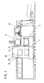
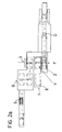
- FIGS. 1, 2a and 2b show the schematic structure of the Packing machine according to the invention can be seen.
- a conveyor station F is a layer of cans D by means of a slide not shown here in a gradually lowerable Packing gauge 2 pushed.
- the shape of the packaging gauge 2 corresponds to the shape to be achieved Packaging. If the cans D are to be strapped with a strap, the packaging gauge preferably has a hexagonal Form as indicated in the figure with the reference number 2 ' is. If the cans D are packed in boxes, corresponds to the packing gauge 2 of the opening of the box and is, as can be seen in FIG. 2a, preferably rectangular.
- the packaging gauge 2 becomes the conveyor station F to the packaging station V driven. In this example, it becomes this lowered.
- the cans D together in the form of a tight packing from the packaging theory 2 removed to them with common packaging Mistake. Further transport takes place using a suction pad 3, which has a flat suction surface, the is aligned parallel to the packaging apprenticeship.
- the suction pad 3 is in the direction of the can delivery from the packaging gauge 2, the filling direction, movable and has a front End position at the packaging location and a rear end position on which the packaged cans D on a perpendicular to Filling direction slidable transport plate get where they are held by a press arm pressing from above and with this transport plate to a next processing station B are passed on.
- the type of packaging can be selected between box filling and strapping.
- One packaging module each can be inserted into a designated bay of the packaging machine, more precisely between the lowered packaging jig 2 and the suction gripper 3, and precisely positioned and locked using adjusting rollers or rails.
- Each packaging module consists of a basal body on which either a box or a tape feeder is arranged.
- the packaging material i.e. the box or the band, is brought to the packaging station in a plane, the feed plane, which is perpendicular to the direction in which the cans D are dispensed from the packaging gauge, the filling direction.
- the packaging gauge 2 and the suction pad 3 are required for both types of packaging. They can therefore be identical or, depending on the shape of the desired packaging, can also be replaced when changing the packaging module. However, it is essential that the same holders and displacement mechanisms are used for all types of packaging gauges or suction cups.
- the packaging module a strapping or a box filling module.
- the strapping module consists of known elements and is therefore not shown in detail here. On the strapping module there is a roll of tape and means for strapping. The remaining elements described here are part of the stationary packaging machine.
- the lowered, with cans D filled packing gauge is opened in the horizontal direction the strapping module steered and the strap around the cans D looped, cut and the ends welded.
- a Suction cup with several suction openings is on the packaging gauge opposite side to the cans D, whereby he draws the cans D with negative pressure.
- the Can D aligned so that the can bottoms become a suction cup are executed. At the same time or afterwards it will now empty packaging gauge moved back horizontally and again raised to conveyor station F.
- the suction pad is in the loading direction drove back from the place of packaging and leads the strapped cans D with. Arrived in the rear end position the strapped can package 9 on the perpendicular to the loading direction slidable transport plate, is with a from above on the Strapping package pressing arm pressed and with this transport plate passed on to the processing station.
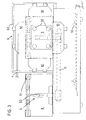
- the box filling module 1 is shown in FIGS. 3, 4a and 4b shown.
- the box filling module 1 has a vertical standing box carrier 5, which in the feed plane from an outer end position to an inner one, the packaging theory adjacent end position is movable.
- the box carrier 5 by a carriage formed, which by means of a linear cylinder 11 in a horizontal Direction along a slot 12 in the box filling module 1 can be moved back and forth.
- the box carrier a swivel arm, which in the Feed level is pivotable.
- the box carrier 5 has a support arm 50 and at least one, here three, adjustable booms 51 arranged thereon on. It is best seen in Figure 3.
- One too filling, open box 8 is in the side position in the outer end position placed on the box carrier 5.
- This is thanks to the adjustable bracket 51 on the Box size adjustable.
- Support arm and boom are designed that with the box attached, the box bottom on the side facing away from the packaging gauge. The opening of the box is thus on the side. If if the box carrier moves horizontally, the box becomes according to the orientation of the packaging gauge on the Box carrier turned up. In the case of the swiveling box carrier the box is arranged rotated by 90 °.
- the box carrier 5 moves with the box 8 to the packaging station between the lowered packaging gauge 2 and the suction gripper 3 to its inner end position, which is shown in FIG. 4a with broken lines.
- the box 8 is taken over by the suction gripper 3, the suction gripper 3 being simultaneously or subsequently pushed horizontally in the direction of the lowered packaging gauge until it touches the bottom 80 of the box 8. He sucks on the box bottom 80 and moves the box away from the box carrier 5.
- the suction gripper 3 has a square suction plate with at least four suction cups 30, which are arranged in the corners of the suction plate.
- the box carrier 5 is now moved at least until it completely clears the opening of the box. It is preferably moved back to its outer end position in order to accommodate a new box.
- the suction gripper 3, on the other hand travels with the box 8 to the lowered packaging jig 2, as shown in broken lines in FIG.
- the box becomes here preferably taken up by a box holder 6.
- This box holder 6 is stationary on the box filling module 1 arranged and consists of a box holder frame 60 and several, here four, displaceable clamping elements 61.
- the box holder 6 is used to fix the side walls of the Box while filling.
- the clamping elements 61 have for this each have an inclined plate, which in the Protrude box opening and by sliding the side walls press slightly outwards. Now the cans D from the packaging gauge 2 by means of a not shown here Slider pushed into the box 8, the inclined plates serve as a guide.
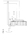
- a protective plate 7, which with the movement mechanism of the suction pad 3 is coupled, at least in part via the opening of the now swung filled box and preferably on these pressed so that the cans D are kept in the box are. These directions of movement are shown in FIG Arrows shown. It has been shown that it is sufficient if the protective plate is the top or more of the top Layers of cans D covered.
- the suction gripper 3 pulls the filled box 8 from the packaging station in horizontal and perpendicular to the feed direction direction back to the rear end position.
- the box thus also reaches the Transport plate slidable perpendicular to the loading direction, where them from the suction pad 3 by deactivating the negative pressure released by a press arm pressing on them from above held and with the transport plate to the processing station is passed on.
Landscapes
- Engineering & Computer Science (AREA)
- Mechanical Engineering (AREA)
- Container Filling Or Packaging Operations (AREA)
- Basic Packing Technique (AREA)
Applications Claiming Priority (2)
| Application Number | Priority Date | Filing Date | Title |
|---|---|---|---|
| CH02536/96A CH691899A5 (de) | 1996-10-17 | 1996-10-17 | Verfahren und Vorrichtung zum Verpacken von Dosen oder Tuben. |
| CH2536/96 | 1996-10-17 |
Publications (1)
| Publication Number | Publication Date |
|---|---|
| EP0836995A1 true EP0836995A1 (fr) | 1998-04-22 |
Family
ID=4236014
Family Applications (1)
| Application Number | Title | Priority Date | Filing Date |
|---|---|---|---|
| EP97810599A Withdrawn EP0836995A1 (fr) | 1996-10-17 | 1997-08-26 | Procédé et dispositif pour emballer des boítes ou des tubes |
Country Status (4)
| Country | Link |
|---|---|
| US (1) | US5862649A (fr) |
| EP (1) | EP0836995A1 (fr) |
| CA (1) | CA2218194A1 (fr) |
| CH (1) | CH691899A5 (fr) |
Cited By (2)
| Publication number | Priority date | Publication date | Assignee | Title |
|---|---|---|---|---|
| DE10316853B4 (de) * | 2003-04-11 | 2007-10-31 | Aisa Automation Industrielle S.A. | Vorrichtung zum automatischen Abpacken von Behältern |
| EP2735515A1 (fr) * | 2012-11-26 | 2014-05-28 | Pester Pac Automation GmbH | Dispositif pour dresser un carton à partir d'un flan |
Families Citing this family (8)
| Publication number | Priority date | Publication date | Assignee | Title |
|---|---|---|---|---|
| WO2001028856A1 (fr) | 1999-10-15 | 2001-04-26 | Hartness International, Inc. | Appareil et procede d'encaissage et de decaissage a mouvement circulaire continu |
| US7114535B2 (en) * | 2003-08-28 | 2006-10-03 | Hartness International, Inc. | Circular motion filling machine and method |
| US7278531B2 (en) * | 2004-06-29 | 2007-10-09 | Hartness International, Inc. | Flexible conveyor and connection elements |
| US7331156B2 (en) * | 2004-06-29 | 2008-02-19 | Hartness International, Inc. | System for securely conveying articles and related components |
| US7299832B2 (en) * | 2004-06-29 | 2007-11-27 | Hartness International, Inc. | Rotary filling machine and related components, and related method |
| ITTO20080318A1 (it) * | 2008-04-24 | 2009-10-25 | Elsag Datamat Spa | Dispositivo di trattamento di oggetti postali disposti a pacco |
| KR20190011757A (ko) | 2016-05-24 | 2019-02-07 | 트와인 솔루션즈 엘티디. | 실 및 그 일부를 처리하기 위한 시스템, 기기 및 방법 |
| CN108438333B (zh) * | 2018-03-30 | 2024-05-03 | 漳州杰安塑料有限公司 | 一种半自动吸管装盒机 |
Citations (3)
| Publication number | Priority date | Publication date | Assignee | Title |
|---|---|---|---|---|
| FR2352709A1 (fr) * | 1976-05-28 | 1977-12-23 | Alusuisse | Procede et dispositif pour le paquetage de recipients cylindriques |
| DE2825800A1 (de) * | 1978-03-17 | 1979-09-20 | Alusuisse | Vorrichtung zum buendeln von im wesentlichen zylindrischen gegenstaenden zu paketen |
| US4386490A (en) * | 1981-04-13 | 1983-06-07 | Armour-Dial, Inc. | Apparatus for collating, cutting and packing food products |
Family Cites Families (12)
| Publication number | Priority date | Publication date | Assignee | Title |
|---|---|---|---|---|
| US5704A (en) * | 1848-08-10 | Aik-heatiwg stove | ||
| US3054236A (en) * | 1959-06-22 | 1962-09-18 | Vol Pak Inc | Multi-purpose packaging machine |
| US3383829A (en) * | 1966-02-02 | 1968-05-21 | James M. Duddleston | Combined paper carton and plastic bottle filling machine |
| US3465494A (en) * | 1967-05-04 | 1969-09-09 | Haskon Inc | Filling and sealing machine |
| US4534153A (en) * | 1983-07-11 | 1985-08-13 | Owens--Illinois, Inc. | Method and apparatus for packing plastic bottles |
| DE3339924A1 (de) * | 1983-11-04 | 1985-05-15 | Robert Bosch Gmbh, 7000 Stuttgart | Verpackungsmaschine |
| DE3410685A1 (de) * | 1984-03-23 | 1985-10-03 | Robert Bosch Gmbh, 7000 Stuttgart | Formatumstellbare verpackungsmaschine |
| ES2047305T3 (es) * | 1990-01-25 | 1994-02-16 | Pamag Ag | Procedimiento para el empaquetado en cajas de envases o tubos y maquina para la realizacion del procedimiento. |
| CH683171A5 (de) * | 1991-04-04 | 1994-01-31 | Pamag Ag | Verfahren zur Uebernahme von kontinuierlich angelieferten Produkten einer Produktionsanlage und jeweils diskontinuierliche Abgabe einer Anzahl dieser Produkte bei einer Abgabestation. |
| ZA945755B (en) * | 1993-08-11 | 1995-03-15 | Metal Box Co South Africa | The packaging of articles |
| ZA949233B (en) * | 1993-12-01 | 1995-08-01 | Metal Box Co South Africa | The packing of cylindrical articles. |
| US5636498A (en) * | 1995-05-12 | 1997-06-10 | George Gordon Associates, Inc. | Bulk straw loading system |
-
1996
- 1996-10-17 CH CH02536/96A patent/CH691899A5/de not_active IP Right Cessation
-
1997
- 1997-08-26 EP EP97810599A patent/EP0836995A1/fr not_active Withdrawn
- 1997-10-14 CA CA002218194A patent/CA2218194A1/fr not_active Abandoned
- 1997-10-14 US US08/949,579 patent/US5862649A/en not_active Expired - Fee Related
Patent Citations (3)
| Publication number | Priority date | Publication date | Assignee | Title |
|---|---|---|---|---|
| FR2352709A1 (fr) * | 1976-05-28 | 1977-12-23 | Alusuisse | Procede et dispositif pour le paquetage de recipients cylindriques |
| DE2825800A1 (de) * | 1978-03-17 | 1979-09-20 | Alusuisse | Vorrichtung zum buendeln von im wesentlichen zylindrischen gegenstaenden zu paketen |
| US4386490A (en) * | 1981-04-13 | 1983-06-07 | Armour-Dial, Inc. | Apparatus for collating, cutting and packing food products |
Cited By (2)
| Publication number | Priority date | Publication date | Assignee | Title |
|---|---|---|---|---|
| DE10316853B4 (de) * | 2003-04-11 | 2007-10-31 | Aisa Automation Industrielle S.A. | Vorrichtung zum automatischen Abpacken von Behältern |
| EP2735515A1 (fr) * | 2012-11-26 | 2014-05-28 | Pester Pac Automation GmbH | Dispositif pour dresser un carton à partir d'un flan |
Also Published As
| Publication number | Publication date |
|---|---|
| US5862649A (en) | 1999-01-26 |
| CH691899A5 (de) | 2001-11-30 |
| CA2218194A1 (fr) | 1998-04-17 |
Similar Documents
| Publication | Publication Date | Title |
|---|---|---|
| EP0298294B1 (fr) | Dispositif pour le groupement de paquets | |
| DE2744158A1 (de) | Vorrichtung zum verpacken komprimierbarer artikel, z.b. wegwerfwindeln o.dgl., in kartons | |
| DE10127896B4 (de) | Übergabevorrichtung und -verfahren für Folienbeutel | |
| CH671566A5 (fr) | ||
| EP0062249B1 (fr) | Machine d'emballage | |
| DE3813729A1 (de) | Stapeln von buendeln flachgefalteter schachteln aus wellpappe | |
| EP1020359A2 (fr) | Dispositif pour transporter et tourner en même temps des objets, spécialement des boítes pliantes | |
| EP0836995A1 (fr) | Procédé et dispositif pour emballer des boítes ou des tubes | |
| DE3700146A1 (de) | Maschine zur umreifung von packstuecken in laengs- und querrichtung | |
| DE4127854C2 (de) | Vorrichtung zum Zuführen von zwei plattenförmigen Zuschnitten zu einer Tiefziehmaschine | |
| EP0077992B1 (fr) | Appareil pour contrôler la pesée d'emballages | |
| DE2304994C2 (de) | Vorrichtung zum Einbringen von Packungen in Transportbehälter | |
| EP1975074B1 (fr) | Dispositif et procédé de chargement et de déchargement d'une multitude d'objets installés dans un récipient de réception ouvert sur le dessus | |
| DE3729373C2 (fr) | ||
| DE102005002532A1 (de) | Vorrichtung und Verfahren zum automatisierten und zeitgleichen Bereitstellen und Wechseln von mindestens zwei Rollen aus Papierbahnen oder dergleichen für einen nachgeordneten Formatschneider | |
| DE3632691C2 (fr) | ||
| DE1228557B (de) | Foerdereinrichtung fuer die Benutzung bei einer Umschnuerungs- oder Umreifungsmaschine | |
| DE2416579A1 (de) | Vorrichtung zum einpacken von behaeltergruppen in trays | |
| DE1611884C2 (de) | Vorrichtung zum Zufuhren von Karton zuschnitten zu einer Verpackungsvornch tung | |
| DE4210749C2 (de) | Vorrichtung zum Einbringen von Beutelpackungen in einen Sammelbehälter | |
| DE2435671B2 (de) | Verfahren und Vorrichtung zum Handhaben und Lagern von länglichen Gegenständen | |
| DE2063282A1 (de) | Vorrichtung zum Transport von zu Paketen zusammengefaßten Zeitschriften-Teilprodukten von Hochdruck- oder Tiefdruck-Rotationsmaschinen zu Heftmaschinen mittels Transportbehälter | |
| DE2001760C (de) | Vorrichtung zum Einbringen von Gegenstanden in einen Sammelbehalter | |
| DE19945386A1 (de) | Verfahren und Vorrichtung zum Verpacken von Rollenware, insbesondere Wickelrollen aus Kunststofffolie | |
| EP1634826A1 (fr) | Dispositif et procédé pour l'empilage d'articles dans un conteneur de transport |
Legal Events
| Date | Code | Title | Description |
|---|---|---|---|
| PUAI | Public reference made under article 153(3) epc to a published international application that has entered the european phase |
Free format text: ORIGINAL CODE: 0009012 |
|
| AK | Designated contracting states |
Kind code of ref document: A1 Designated state(s): BE CH DE FR GB IT LI LU NL |
|
| AX | Request for extension of the european patent |
Free format text: AL;LT;LV;RO;SI |
|
| 17P | Request for examination filed |
Effective date: 19980924 |
|
| AKX | Designation fees paid |
Free format text: BE CH DE FR GB IT LI LU NL |
|
| RBV | Designated contracting states (corrected) |
Designated state(s): BE CH DE FR GB IT LI LU NL |
|
| RAP1 | Party data changed (applicant data changed or rights of an application transferred) |
Owner name: HINTERKOPF GMBH |
|
| GRAH | Despatch of communication of intention to grant a patent |
Free format text: ORIGINAL CODE: EPIDOS IGRA |
|
| STAA | Information on the status of an ep patent application or granted ep patent |
Free format text: STATUS: THE APPLICATION IS DEEMED TO BE WITHDRAWN |
|
| 18D | Application deemed to be withdrawn |
Effective date: 20030301 |