EP0837219A1 - Moteur à pistons rotatifs - Google Patents
Moteur à pistons rotatifs Download PDFInfo
- Publication number
- EP0837219A1 EP0837219A1 EP97118154A EP97118154A EP0837219A1 EP 0837219 A1 EP0837219 A1 EP 0837219A1 EP 97118154 A EP97118154 A EP 97118154A EP 97118154 A EP97118154 A EP 97118154A EP 0837219 A1 EP0837219 A1 EP 0837219A1
- Authority
- EP
- European Patent Office
- Prior art keywords
- rotary piston
- rotary
- piston engine
- engine according
- pistons
- Prior art date
- Legal status (The legal status is an assumption and is not a legal conclusion. Google has not performed a legal analysis and makes no representation as to the accuracy of the status listed.)
- Withdrawn
Links
- 238000002485 combustion reaction Methods 0.000 claims description 41
- 239000007789 gas Substances 0.000 claims description 20
- XLYOFNOQVPJJNP-UHFFFAOYSA-N water Substances O XLYOFNOQVPJJNP-UHFFFAOYSA-N 0.000 claims description 12
- 239000000446 fuel Substances 0.000 claims description 11
- 238000006243 chemical reaction Methods 0.000 claims description 6
- 239000000203 mixture Substances 0.000 claims description 6
- 238000013461 design Methods 0.000 claims description 3
- 230000002093 peripheral effect Effects 0.000 claims description 3
- 230000009467 reduction Effects 0.000 claims description 2
- 238000009413 insulation Methods 0.000 claims 1
- 239000003380 propellant Substances 0.000 claims 1
- 239000000126 substance Substances 0.000 abstract 1
- 239000001257 hydrogen Substances 0.000 description 6
- 229910052739 hydrogen Inorganic materials 0.000 description 6
- 239000001301 oxygen Substances 0.000 description 6
- 229910052760 oxygen Inorganic materials 0.000 description 6
- UFHFLCQGNIYNRP-UHFFFAOYSA-N Hydrogen Chemical compound [H][H] UFHFLCQGNIYNRP-UHFFFAOYSA-N 0.000 description 5
- QVGXLLKOCUKJST-UHFFFAOYSA-N atomic oxygen Chemical compound [O] QVGXLLKOCUKJST-UHFFFAOYSA-N 0.000 description 4
- 230000008901 benefit Effects 0.000 description 4
- 238000001816 cooling Methods 0.000 description 4
- 239000007921 spray Substances 0.000 description 4
- 230000008859 change Effects 0.000 description 3
- 230000006835 compression Effects 0.000 description 2
- 238000007906 compression Methods 0.000 description 2
- 230000008878 coupling Effects 0.000 description 2
- 238000010168 coupling process Methods 0.000 description 2
- 238000005859 coupling reaction Methods 0.000 description 2
- 238000010586 diagram Methods 0.000 description 2
- 150000002431 hydrogen Chemical class 0.000 description 2
- 238000005507 spraying Methods 0.000 description 2
- 230000007704 transition Effects 0.000 description 2
- MYMOFIZGZYHOMD-UHFFFAOYSA-N Dioxygen Chemical compound O=O MYMOFIZGZYHOMD-UHFFFAOYSA-N 0.000 description 1
- 230000001133 acceleration Effects 0.000 description 1
- 239000002826 coolant Substances 0.000 description 1
- 239000000498 cooling water Substances 0.000 description 1
- 230000007423 decrease Effects 0.000 description 1
- 238000011161 development Methods 0.000 description 1
- 238000005516 engineering process Methods 0.000 description 1
- 239000012530 fluid Substances 0.000 description 1
- 238000010438 heat treatment Methods 0.000 description 1
- 238000002347 injection Methods 0.000 description 1
- 239000007924 injection Substances 0.000 description 1
- 239000007788 liquid Substances 0.000 description 1
- 238000005461 lubrication Methods 0.000 description 1
- 238000004519 manufacturing process Methods 0.000 description 1
- 230000007246 mechanism Effects 0.000 description 1
- 238000000034 method Methods 0.000 description 1
- 238000002156 mixing Methods 0.000 description 1
- 230000008569 process Effects 0.000 description 1
- 239000000376 reactant Substances 0.000 description 1
- 238000007789 sealing Methods 0.000 description 1
- 210000002023 somite Anatomy 0.000 description 1
- 239000007858 starting material Substances 0.000 description 1
- 238000012360 testing method Methods 0.000 description 1
- 238000012546 transfer Methods 0.000 description 1
Images



Classifications
-
- F—MECHANICAL ENGINEERING; LIGHTING; HEATING; WEAPONS; BLASTING
- F01—MACHINES OR ENGINES IN GENERAL; ENGINE PLANTS IN GENERAL; STEAM ENGINES
- F01C—ROTARY-PISTON OR OSCILLATING-PISTON MACHINES OR ENGINES
- F01C1/00—Rotary-piston machines or engines
- F01C1/08—Rotary-piston machines or engines of intermeshing engagement type, i.e. with engagement of co- operating members similar to that of toothed gearing
- F01C1/12—Rotary-piston machines or engines of intermeshing engagement type, i.e. with engagement of co- operating members similar to that of toothed gearing of other than internal-axis type
- F01C1/126—Rotary-piston machines or engines of intermeshing engagement type, i.e. with engagement of co- operating members similar to that of toothed gearing of other than internal-axis type with elements extending radially from the rotor body not necessarily cooperating with corresponding recesses in the other rotor, e.g. lobes, Roots type
-
- F—MECHANICAL ENGINEERING; LIGHTING; HEATING; WEAPONS; BLASTING
- F02—COMBUSTION ENGINES; HOT-GAS OR COMBUSTION-PRODUCT ENGINE PLANTS
- F02B—INTERNAL-COMBUSTION PISTON ENGINES; COMBUSTION ENGINES IN GENERAL
- F02B53/00—Internal-combustion aspects of rotary-piston or oscillating-piston engines
Definitions
- the invention relates to a rotary piston engine that deals with a combustible supplied under low pressure Can operate gas / oxygen mixture.
- the second valve has the advantage of being a larger one Volume can flow in faster. This is for the Charging process of the combustion chamber is extremely important.
- the engine according to the invention are in the Housing two counter-rotating preferably identically designed rotary pistons.
- the two axes of rotation of the Rotary pistons are parallel to each other.
- the design of the two rotary pistons is such that the two opposite circumferential areas or axially extending circumferential lines of the rotary pistons always in have substantially the same distance from each other.
- the same also applies to the housing wall against - overlying circumferential areas or lines of the two pistons
- this area of the peripheral surfaces of the Rotary piston essentially the same distance to Housing on.
- the two rotary pistons are inside the housing of the Motor arranged between the inlet and the outlet. She So divide the housing into two parts, being the inlet and shield the outlet from each other.
- Hydrogen and oxygen are preferred as fuel used, which separated the interior of the housing via the inlet be fed.
- a particular advantage is building one Mono gas column for isolating the valves from the combustion chamber. Since the valves are now in the area where there is no reaction partner is present, they are only slightly warmed. she remain functional.
- actio reactio is also to be understood essentially why the previous rotary piston engines had to be operated with little efficiency without valves.
- the new concept of the rotary piston engine has one automatic closing of the supply line after ignition.
- Closure lies behind a gas column with no reactants remains well below the temperature of the combustion chamber, so that the valves can operate in a temperature range in that they don't lose their function.
- the engine only sucks fuel again when the combustion chamber pressure comes below the pressure of the supply line. This is not clocked as with the Otto engine, but only depends on the volume of the rotary pistons (see Fig. 8 (A) - (C) and Fig. 9. It is important that the fuel supply is not interrupted, that a lot of time elapses until the next ignition, and that all of the energy is obtained for rotational work.
- the scooping volume V s is to be used, which performs the pressure reduction (see Fig. 8 (A) - (C) and Fig. 9).
- the initial volume V 1 is 40 [cm] 3 .
- the expanded volume V 2 is 60 [cm] 3 .
- the scoop volume V s 20 [cm] 3 .
- a working cycle is half a turn of a piston. So two work cycles are a full turn.
- the inlet valve opens automatically, not clocked when the supply pressure is 1 [bar].
- the supply pressure is natural adjustable and can therefore be higher, which leads to a leads to higher working pressure.
- the pV diagram for the above Description is shown in Fig.7.
- the opposite ones Area areas or line areas of the rotary pistons as well the opposite surface or line areas between the rotary piston and the housing inner wall one each constant distance.
- For the operation of the Motor according to the invention is therefore not a disadvantage if the rotary pistons rotate in the housing without contact. But this results in the very crucial practical The advantage that there is no need for lubrication.
- the wave is hollow for that designed.
- the inside of the shaft is conically hollow, so that injected cooling water due to the centrifugal force over the sloping surface flows outwards,
- Fig.4 shows a horizontal section through the engine with the Gears of the piston coupling and the gear.
- Figure 5 shows the detail "X".
- the spring shown here is constructed as an "oscillating lock". For the time of low pressure, it lets through H 2 and O 2 . After ignition, it automatically closes the backflow of the gas mixture at a higher pressure. The energy converted into pressure can be converted into rotational energy.
- Figure 6 shows the detail "B".
- the closure shown here is one Alternative to Fig.5, which is in the test.
- the effort to manufacture is larger, but it could be that the closure is more effective. Accelerated loading of the combustion chamber is too expect.
- Fig. 7 shows the pV diagram with and without water spray
- Fig. 8 (A) to (C) the pressure behavior in the combustion chamber.
- the Graphs show the pressure as a function of the scooping volume and the inlet pressure. The valves only open when the pressure in the combustion chamber decreases under the pressure of the supply line. Then the combustion chamber is reloaded.
- FIG. 10 shows the arrangement for spark ignition by a heating coil or a LASER. The same applies here: the ignition mechanism does not have to be clocked.
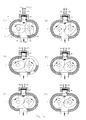
- FIG. 1a A) to (F) each show in cross section a rotary piston motor 10, the two rotary pistons 14, 16 of which are rotatable in a housing 12 are shown in different rotational positions.
- the housing 12 is provided with an inlet 18 and an outlet 20 opposite this.
- Two separate lines 22, 24 for light hydrogen (LH 2 ) and air-oxygen (O 2 ) lead into the interior of the housing 12 via the inlet 18.
- LH 2 light hydrogen
- O 2 air-oxygen
- These "fuels” also other fuels
- the engine is rotated as usual via a starter he H 2 , which reacts immediately when the ignition is switched on.
- a small pressure vessel designed as required which is supplied with reserve pressure (max. pressure) of each gas type via a diaphragm pump operated by the motor, can supply the required pressure (vernacular ,, To give gas"). Unlike conventional combustion engines, this is not fuel injection.
- the two rotary pistons 14, 16 are of identical design and each have a symmetrical shape.
- the outer contour of the two rotary pistons 14, 16 are constructed from a polygon and short arcs.
- the pressure then causes the rotary piston 14 to be set in rotation in the direction of the arrow shown;
- the rotary piston 16 is also set in rotary motion by coupling the two pistons.
- the rotary piston 16 would not experience any rotary movement on its own, since the sum of all of the rotary piston 16 due to the pressure increase in the Torque acting combustion chamber is zero. However, this does not apply to the rotary piston 14, which is why it is driven in rotation.
- the housing 12 itself is provided with a plurality of cooling channels 34 for cooling with a cooling medium, in particular water.
- the bearings 32 are also provided with cooling channels 34, so that the heat transfer via the axes of rotation 26 can be dissipated quickly from the housing 12 via the cooling.
- One of the axes of rotation 26 of both rotary pistons 14, 16 forms the drive shaft of the motor 10, the rotation of which is implemented in a gear 36.
Landscapes
- Engineering & Computer Science (AREA)
- Mechanical Engineering (AREA)
- General Engineering & Computer Science (AREA)
- Output Control And Ontrol Of Special Type Engine (AREA)
Applications Claiming Priority (6)
| Application Number | Priority Date | Filing Date | Title |
|---|---|---|---|
| DE1996143313 DE19643313C2 (de) | 1996-10-21 | 1996-10-21 | Rotationskolbenmotor |
| DE19643313 | 1996-10-21 | ||
| DE1996145924 DE19645924C2 (de) | 1996-11-07 | 1996-11-07 | Rotationskolbenmotor mit innerer Kühlung |
| DE19645924 | 1996-11-07 | ||
| DE19711172 | 1997-03-18 | ||
| DE1997111172 DE19711172A1 (de) | 1997-03-18 | 1997-03-18 | Rotationskolben-Motor Reduzierung des Ladungsverlustes und besserer Wirkungsgrad der H·2·-Verbrennung durch Einsprühung von Wasser |
Publications (1)
| Publication Number | Publication Date |
|---|---|
| EP0837219A1 true EP0837219A1 (fr) | 1998-04-22 |
Family
ID=27216747
Family Applications (1)
| Application Number | Title | Priority Date | Filing Date |
|---|---|---|---|
| EP97118154A Withdrawn EP0837219A1 (fr) | 1996-10-21 | 1997-10-20 | Moteur à pistons rotatifs |
Country Status (1)
| Country | Link |
|---|---|
| EP (1) | EP0837219A1 (fr) |
Cited By (1)
| Publication number | Priority date | Publication date | Assignee | Title |
|---|---|---|---|---|
| DE102024106862B3 (de) | 2024-03-11 | 2025-03-20 | Karl Schmid | Dampferzeuger und Heizsystem mit Dampferzeuger sowie ein Verfahren zum Betreiben eines solchen Dampferzeugers |
Citations (4)
| Publication number | Priority date | Publication date | Assignee | Title |
|---|---|---|---|---|
| US4324537A (en) * | 1979-11-13 | 1982-04-13 | Usher Meyman | Rotary machine with a plurality of rotors having peripheral rolling contact |
| US4696268A (en) * | 1984-06-16 | 1987-09-29 | Otto Zimmermann | Rotary piston internal combustion engine with water injection |
| EP0421499A2 (fr) * | 1989-10-02 | 1991-04-10 | Tocew Lee | Machine rotative à fluide |
| DE4343165A1 (de) * | 1993-10-13 | 1995-04-20 | Heinz A Dr Selic | Rotationskolben-Motor |
-
1997
- 1997-10-20 EP EP97118154A patent/EP0837219A1/fr not_active Withdrawn
Patent Citations (4)
| Publication number | Priority date | Publication date | Assignee | Title |
|---|---|---|---|---|
| US4324537A (en) * | 1979-11-13 | 1982-04-13 | Usher Meyman | Rotary machine with a plurality of rotors having peripheral rolling contact |
| US4696268A (en) * | 1984-06-16 | 1987-09-29 | Otto Zimmermann | Rotary piston internal combustion engine with water injection |
| EP0421499A2 (fr) * | 1989-10-02 | 1991-04-10 | Tocew Lee | Machine rotative à fluide |
| DE4343165A1 (de) * | 1993-10-13 | 1995-04-20 | Heinz A Dr Selic | Rotationskolben-Motor |
Cited By (1)
| Publication number | Priority date | Publication date | Assignee | Title |
|---|---|---|---|---|
| DE102024106862B3 (de) | 2024-03-11 | 2025-03-20 | Karl Schmid | Dampferzeuger und Heizsystem mit Dampferzeuger sowie ein Verfahren zum Betreiben eines solchen Dampferzeugers |
Similar Documents
| Publication | Publication Date | Title |
|---|---|---|
| DE4191140C2 (de) | Drehkolbenmaschine | |
| DE3937359A1 (de) | Brennkraftmaschine | |
| DE1301611B (de) | Innenachsige Kreiskolben-Brennkraftmaschine mit Schlupfeingriff | |
| DE3735866A1 (de) | Turbinenverbundmotor | |
| DE2710301A1 (de) | Verbrennungskraftmaschine | |
| DE2233014A1 (de) | Aufladbare rotationskolbenbrennkraftmaschine | |
| DE102009029950A1 (de) | Garri-Brennstoffrotationskolbenmotor | |
| DE2261547A1 (de) | Rotationskolbenmaschine | |
| DE19711084A1 (de) | Rotationskolbenmaschine | |
| WO2012130226A2 (fr) | Moteur à combustion interne doté d'un rotor tournant autour de son axe | |
| DE69406799T2 (de) | Maschine | |
| EP0136565A2 (fr) | Dispositif comprenant un moteur à pistons et un mécanisme d'entraînement | |
| DE102007019985A1 (de) | Kraft- und Arbeitsmaschine mit Rotationskolben | |
| EP1846646A1 (fr) | Moteur a combustion interne a rotor et a pistons | |
| DE2250589A1 (de) | Rotationskolbenmaschine | |
| DE69627167T2 (de) | Rotierende brennkraftmaschine | |
| EP0837219A1 (fr) | Moteur à pistons rotatifs | |
| DE3317431A1 (de) | Viertakt-drehkolbenmotor | |
| EP0166244A2 (fr) | Machine rotative | |
| DE2429553A1 (de) | Kreiskolbenmotor | |
| DE402209C (de) | Brennkraftturbine | |
| DE102006014425A1 (de) | Brennstoffrotationskolbenmotor | |
| DE4343165A1 (de) | Rotationskolben-Motor | |
| DE3321270A1 (de) | Drehkolbenmotor | |
| DE69917632T2 (de) | Rotierende Brennkraftmaschine |
Legal Events
| Date | Code | Title | Description |
|---|---|---|---|
| PUAI | Public reference made under article 153(3) epc to a published international application that has entered the european phase |
Free format text: ORIGINAL CODE: 0009012 |
|
| AK | Designated contracting states |
Kind code of ref document: A1 Designated state(s): AT BE CH DE DK ES FI FR GB GR IE IT LI LU MC NL PT |
|
| AX | Request for extension of the european patent |
Free format text: AL;LT;LV;RO;SI |
|
| 17P | Request for examination filed |
Effective date: 19980623 |
|
| AKX | Designation fees paid |
Free format text: AT BE CH DE DK ES FI FR GB GR IE IT LI LU MC NL PT |
|
| RBV | Designated contracting states (corrected) |
Designated state(s): AT BE CH DE DK ES FI FR GB GR IE IT LI LU MC NL PT |
|
| PUAJ | Public notification under rule 129 epc |
Free format text: ORIGINAL CODE: 0009425 |
|
| 18D | Application deemed to be withdrawn |
Effective date: 20020423 |
|
| STAA | Information on the status of an ep patent application or granted ep patent |
Free format text: STATUS: THE APPLICATION IS DEEMED TO BE WITHDRAWN |
|
| RAP1 | Party data changed (applicant data changed or rights of an application transferred) |
Owner name: SELIC, HEINZ A DR. |
|
| RIN1 | Information on inventor provided before grant (corrected) |
Inventor name: SELIC, HEINZ A DR. |