EP0837265A2 - Tendeur de chaíne - Google Patents
Tendeur de chaíne Download PDFInfo
- Publication number
- EP0837265A2 EP0837265A2 EP97307754A EP97307754A EP0837265A2 EP 0837265 A2 EP0837265 A2 EP 0837265A2 EP 97307754 A EP97307754 A EP 97307754A EP 97307754 A EP97307754 A EP 97307754A EP 0837265 A2 EP0837265 A2 EP 0837265A2
- Authority
- EP
- European Patent Office
- Prior art keywords
- piston
- chain
- chamber
- chain tensioner
- hydraulic fluid
- Prior art date
- Legal status (The legal status is an assumption and is not a legal conclusion. Google has not performed a legal analysis and makes no representation as to the accuracy of the status listed.)
- Granted
Links
Images
Classifications
-
- F—MECHANICAL ENGINEERING; LIGHTING; HEATING; WEAPONS; BLASTING
- F16—ENGINEERING ELEMENTS AND UNITS; GENERAL MEASURES FOR PRODUCING AND MAINTAINING EFFECTIVE FUNCTIONING OF MACHINES OR INSTALLATIONS; THERMAL INSULATION IN GENERAL
- F16H—GEARING
- F16H7/00—Gearings for conveying rotary motion by endless flexible members
- F16H7/08—Means for varying tension of belts, ropes or chains
- F16H7/0829—Means for varying tension of belts, ropes or chains with vibration damping means
- F16H7/0836—Means for varying tension of belts, ropes or chains with vibration damping means of the fluid and restriction type, e.g. dashpot
-
- F—MECHANICAL ENGINEERING; LIGHTING; HEATING; WEAPONS; BLASTING
- F16—ENGINEERING ELEMENTS AND UNITS; GENERAL MEASURES FOR PRODUCING AND MAINTAINING EFFECTIVE FUNCTIONING OF MACHINES OR INSTALLATIONS; THERMAL INSULATION IN GENERAL
- F16H—GEARING
- F16H7/00—Gearings for conveying rotary motion by endless flexible members
- F16H7/08—Means for varying tension of belts, ropes or chains
- F16H2007/0802—Actuators for final output members
- F16H2007/0806—Compression coil springs
-
- F—MECHANICAL ENGINEERING; LIGHTING; HEATING; WEAPONS; BLASTING
- F16—ENGINEERING ELEMENTS AND UNITS; GENERAL MEASURES FOR PRODUCING AND MAINTAINING EFFECTIVE FUNCTIONING OF MACHINES OR INSTALLATIONS; THERMAL INSULATION IN GENERAL
- F16H—GEARING
- F16H7/00—Gearings for conveying rotary motion by endless flexible members
- F16H7/08—Means for varying tension of belts, ropes or chains
- F16H7/0848—Means for varying tension of belts, ropes or chains with means for impeding reverse motion
- F16H2007/0859—Check valves
-
- F—MECHANICAL ENGINEERING; LIGHTING; HEATING; WEAPONS; BLASTING
- F16—ENGINEERING ELEMENTS AND UNITS; GENERAL MEASURES FOR PRODUCING AND MAINTAINING EFFECTIVE FUNCTIONING OF MACHINES OR INSTALLATIONS; THERMAL INSULATION IN GENERAL
- F16H—GEARING
- F16H7/00—Gearings for conveying rotary motion by endless flexible members
- F16H7/08—Means for varying tension of belts, ropes or chains
- F16H2007/0889—Path of movement of the finally actuated member
- F16H2007/0891—Linear path
Definitions
- the present invention relates to a chain tensioner particularly, but not exclusively, of the kind for maintaining tension in a transmission chain of an internal combustion engine.
- tension is conventionally imparted to the chain by means of a tensioner that comprises a piston that is biased out of a cylinder by means of hydraulic pressure, spring force or a combination thereof.
- a tensioning shoe is connected to the end of the piston and bears against the chain.
- a chain tensioner for tensioning a chain in a drive of an internal combustion engine, comprising a piston displaceable within a chamber and biased by a spring so that it protrudes from the housing towards the chain, wherein the chamber has an inlet connected to a supply of hydraulic fluid from the engine and in use the hydraulic fluid acts on each side of the piston with substantially the same pressure such that the piston is damped in both directions when moving in the chamber.
- Preferably surface areas on which the hydraulic fluid acts on each side of the piston are substantially equal.
- the resultant force applied by the hydraulic fluid to the piston is zero.
- the piston is a differential piston so that the hydraulic fluid provides force in addition to the biasing force of the spring.
- the spring may be a compression spring acting between the piston and a wall of the chamber.
- the hydraulic fluid is supplied from oil in the engine.
- a vent may be provided to permit air in the hydraulic fluid to escape from the chamber.
- a check valve may be provided at or adjacent the inlet.
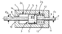
- a cylindrical housing 1 having an interior bore 2 in which a piston 3 is received.
- the piston 3 has a head 4 that fits closely within the bore 2 with a small circumferential clearance 5, and a pair of integral coaxial rods 6,7 one of which projects at each end of the head 4.
- Each rod 6,7 projects coaxial to the bore 2 through an aperture 8,9 provided in an end wall 10,11 of the housing 1.
- the piston head 4 divides the bore 2 into two variable volume chambers 2a. 2b which are interconnected by the circumferential clearance 5 between the piston head 4 and the housing 1.
- a compression spring 12 fitted over the rod 7 that acts between one end of the piston head 4 and the adjacent end wall 11 of the housing 1 so as to bias the piston 3 to the left so that the rod 6 projects out of the end wall 10 of the housing 1.
- the same chamber 2b is connected to a supply of oil from the engine by an inlet 13 in the cylindrical wall of the housing 1.
- the diameter d 1 of rod 7 is less than the diameter d 2 of the other rod 6.
- the diameter of thc piston head 4 is indicated by dimension D.
- the tensioner is assembled, for example, in a balance shaft transmission (not shown) of an internal combustion engine which comprises a chain (not shown) for transmitting driving force from the engine crankshaft (not shown) to one or more balance shafts that are designed to damp engine vibrations.
- Each balance shaft has a driven sprocket (not shown) to which the chain is connected.
- the tensioner is positioned so that a tensioning shoe (not shown) connected to the end of rod 6 bears against the chain.
- the compression spring 12 biases the rod 6 out of the piston housing 1 and against the chain thereby providing tension to the chain.
- Oil from the engine is supplied by a pressure line (not shown) and enters the housing at chamber 2b through the inlet 13.
- the oil is able to pass through the clearance 5 between the piston head 4 and the housing 1 to occupy chamber 2a so that equal hydraulic pressure acts on both ends of the piston head 4.
- a small clearance 14 is provided between rod 6 and the end wall 10 of the housing 1 that defines aperture 8 so as to ensure air is purged from the oil in the housing 1 when the engine is started. This purging of air avoids problems that would occur if air trapped in the oil was compressed during the piston stroke.
- the oil in the housing provides hydraulic damping of tensioner vibration that occurs at certain resonance speeds and as a result of torsional vibration in the driven sprocket to which the chain is connected.
- the tensioning force applied to the chain is set by the relatively low mechanical force applied by the compression spring 12.
- the tensioner may have a differential piston.
- a piston may be provided by making the diameter d 1 of rod 6 greater than that (d 2 ) of rod 7 so that there is a difference between the exposed surface areas S 1 , S 2 .
- the hydraulic pressure can contribute to the tension force.
- the size of the piston diameter D and the clearance 14 between the piston head 4 and the housing 1 are selected to provide optimum tensioning and damping for each particular application. For example, if the clearance 14 is too small the passage of oil through the clearance is restricted and damping is impaired. However, if the clearance is too great for the particular application the damping will not be sufficiently effective.
- the design is relatively simple compared to existing design and obviates the need for several features present in existing tensioners. It is therefore of relatively low cost and high reliability. For example. there is no need to providc a throttling arrangement in the supply of oil to the housing or within the housing itself
Landscapes
- Engineering & Computer Science (AREA)
- General Engineering & Computer Science (AREA)
- Mechanical Engineering (AREA)
- Devices For Conveying Motion By Means Of Endless Flexible Members (AREA)
Applications Claiming Priority (2)
| Application Number | Priority Date | Filing Date | Title |
|---|---|---|---|
| GBGB9621440.8A GB9621440D0 (en) | 1996-10-15 | 1996-10-15 | A chain tensioner |
| GB9621440 | 1996-10-15 |
Publications (3)
| Publication Number | Publication Date |
|---|---|
| EP0837265A2 true EP0837265A2 (fr) | 1998-04-22 |
| EP0837265A3 EP0837265A3 (fr) | 1998-09-16 |
| EP0837265B1 EP0837265B1 (fr) | 2001-07-25 |
Family
ID=10801416
Family Applications (1)
| Application Number | Title | Priority Date | Filing Date |
|---|---|---|---|
| EP97307754A Expired - Lifetime EP0837265B1 (fr) | 1996-10-15 | 1997-10-01 | Tendeur de chaíne |
Country Status (6)
| Country | Link |
|---|---|
| US (1) | US5993339A (fr) |
| EP (1) | EP0837265B1 (fr) |
| AT (1) | ATE203586T1 (fr) |
| DE (1) | DE69705793T2 (fr) |
| ES (1) | ES2160896T3 (fr) |
| GB (1) | GB9621440D0 (fr) |
Cited By (1)
| Publication number | Priority date | Publication date | Assignee | Title |
|---|---|---|---|---|
| DE10014701A1 (de) * | 2000-03-24 | 2001-10-04 | Winklhofer & Soehne Gmbh | Spannvorrichtung für Endlostreibelemente |
Families Citing this family (5)
| Publication number | Priority date | Publication date | Assignee | Title |
|---|---|---|---|---|
| US6117033A (en) * | 1998-09-21 | 2000-09-12 | Borgwarner Inc. | Hydraulic tensioner with tuned spring piston |
| AU2003288058A1 (en) * | 2002-11-14 | 2004-06-03 | Novartis Ag | Antibody- or neutrophil-mediated ozone generation |
| DE102005061444A1 (de) | 2005-12-22 | 2007-07-05 | GM Global Technology Operations, Inc., Detroit | Kettenspanneinrichtung für einen Verbrennungsmotor |
| DE102007058007A1 (de) * | 2007-12-03 | 2009-06-04 | Alfa Laval Kolding A/S | Antriebsanordnung für Ventilvorrichtungen |
| CN109058404B (zh) * | 2018-10-26 | 2024-01-02 | 伊维氏传动系统(平湖)有限公司 | 一种集成式液压双活塞张紧器 |
Family Cites Families (20)
| Publication number | Priority date | Publication date | Assignee | Title |
|---|---|---|---|---|
| US2893255A (en) * | 1956-06-07 | 1959-07-07 | Perry Chain Company Ltd | Chain or belt tensioning devices |
| JPS50101780U (fr) * | 1974-01-25 | 1975-08-22 | ||
| GB1513722A (en) * | 1974-06-26 | 1978-06-07 | Renold Ltd | Damper apparatus for applying a tensioning force to a member |
| GB2034655B (en) * | 1978-11-21 | 1982-12-22 | Dowty Meco Ltd | Controlling tension in chain conveyors |
| US4411638A (en) * | 1981-08-27 | 1983-10-25 | Dayco Corporation | Belt tensioner and method of making the same |
| DE3145115C2 (de) * | 1981-11-13 | 1983-12-08 | Dr.Ing.H.C. F. Porsche Ag, 7000 Stuttgart | "Hydraulischer Kettenspanner" |
| US4708696A (en) * | 1985-08-30 | 1987-11-24 | Tsubakimoto Chain Co. | Tensioner for toothed drive belts |
| DE3801290C1 (en) * | 1988-01-19 | 1989-07-20 | Bayerische Motoren Werke Ag, 8000 Muenchen, De | Tensioning device for a chain or belt drive |
| SE459982B (sv) * | 1988-05-19 | 1989-08-28 | Saab Scania Ab | Spaennanordning foer ett i en transmission ingaaende kraftoeverfoeringsorgan |
| DE3832512C1 (en) * | 1988-09-24 | 1990-04-26 | Bayerische Motoren Werke Ag, 8000 Muenchen, De | Tensioning device for an endless flexible transmission |
| IT1228729B (it) * | 1989-03-15 | 1991-07-03 | Pirelli Transmissioni Ind Spa | Dispositivo tenditore per cinghia flessibile di trasmissione. |
| JP2807895B2 (ja) * | 1989-05-10 | 1998-10-08 | 日本発条株式会社 | テンショナ |
| US4976661A (en) * | 1989-08-21 | 1990-12-11 | Nhk Spring Co., Ltd. | Belt or chain tensioner for power transmitting system |
| IT1241217B (it) * | 1990-05-08 | 1993-12-29 | Fiat Auto Spa | Motore a combustione interna con tenditore della catena di trasmissione fra due alberi a camma in testa |
| EP0468084B1 (fr) * | 1990-07-26 | 1993-11-24 | Dr.Ing.h.c. F. Porsche Aktiengesellschaft | Dispositif pour tendre et déplacer un entraînement d'arbre à cames par chaîne |
| DE4023728A1 (de) * | 1990-07-26 | 1992-01-30 | Porsche Ag | Kettenspanner fuer eine brennkraftmaschine |
| DE4100503A1 (de) * | 1991-01-10 | 1992-07-16 | Daimler Benz Ag | Spanneinrichtung fuer ketten- oder riementriebe |
| DE4207322A1 (de) * | 1992-03-07 | 1993-09-09 | Wahler Gmbh & Co Gustav | Betaetigungseinrichtung fuer eine spannvorrichtung |
| FR2715205B1 (fr) * | 1994-01-17 | 1996-04-05 | Sachs Ind Sa | Tendeur hydraulique pour lien sans fin, notamment pour chaîne de transmission de moteur à combustion interne. |
| US5720684A (en) * | 1995-09-06 | 1998-02-24 | Borg-Warner Automotive, Inc. | Hydraulic tensioner with internal pressure relief |
-
1996
- 1996-10-15 GB GBGB9621440.8A patent/GB9621440D0/en active Pending
-
1997
- 1997-10-01 EP EP97307754A patent/EP0837265B1/fr not_active Expired - Lifetime
- 1997-10-01 DE DE69705793T patent/DE69705793T2/de not_active Expired - Lifetime
- 1997-10-01 ES ES97307754T patent/ES2160896T3/es not_active Expired - Lifetime
- 1997-10-01 AT AT97307754T patent/ATE203586T1/de not_active IP Right Cessation
- 1997-10-15 US US08/950,688 patent/US5993339A/en not_active Expired - Lifetime
Cited By (1)
| Publication number | Priority date | Publication date | Assignee | Title |
|---|---|---|---|---|
| DE10014701A1 (de) * | 2000-03-24 | 2001-10-04 | Winklhofer & Soehne Gmbh | Spannvorrichtung für Endlostreibelemente |
Also Published As
| Publication number | Publication date |
|---|---|
| DE69705793T2 (de) | 2002-04-18 |
| ES2160896T3 (es) | 2001-11-16 |
| DE69705793D1 (de) | 2001-08-30 |
| EP0837265B1 (fr) | 2001-07-25 |
| EP0837265A3 (fr) | 1998-09-16 |
| GB9621440D0 (en) | 1996-12-04 |
| ATE203586T1 (de) | 2001-08-15 |
| US5993339A (en) | 1999-11-30 |
Similar Documents
| Publication | Publication Date | Title |
|---|---|---|
| EP0409460B1 (fr) | Tendeur de chaîne | |
| EP0908646B1 (fr) | Tendeur de chaíne hydraulique avec une chemise cupuliforme formée par emboutissage | |
| US5117786A (en) | Chain tensioner for an internal-combustion engine | |
| US7927242B2 (en) | Downward angle settable hydraulic tensioner | |
| US6244982B1 (en) | Hydraulic chain tensioner with a piston having a plurality of sliding elements | |
| JP4367834B2 (ja) | オートテンショナー | |
| US5370584A (en) | Piston design for removing air from a hydraulic tensioner | |
| US5658212A (en) | Chain tensioner for automotive engine | |
| US4601683A (en) | Belt tensioner, part therefor and methods of making the same | |
| US5195479A (en) | Drive apparatus for one or more supplemental apparatuses driven by an internal combustion engine | |
| US5993339A (en) | Chain tensioner with a spring and hydraulic fluid acting on both sides of a piston | |
| KR960009741Y1 (ko) | 자동 인장기 | |
| EP3680514B1 (fr) | Ensemble tendeur pour courroie de machine auxiliaire | |
| US20050148420A1 (en) | Autotensioner | |
| US20180266312A1 (en) | Accessory drive device for engine | |
| US4624652A (en) | Belt tensioner, part therefor and methods of making the same | |
| US4509935A (en) | Belt tensioner and method of making the same | |
| US4708697A (en) | Belt tensioner, part therefor and methods of making the same | |
| EP1056956B1 (fr) | Accouplement conformable | |
| KR100412611B1 (ko) | 다이아프램을 이용한 체인 오토 텐셔너 | |
| KR100412618B1 (ko) | 체인가이드의 댐핑장치 | |
| US8181621B2 (en) | Internal combustion engine with dynamic balancing system | |
| WO2021014471A1 (fr) | Tendeur hydraulique pour distribution de charge uniforme | |
| JP2005140237A (ja) | 巻掛け伝動部材の張力調整装置 | |
| JPS63103784A (ja) | 内燃機関 |
Legal Events
| Date | Code | Title | Description |
|---|---|---|---|
| PUAI | Public reference made under article 153(3) epc to a published international application that has entered the european phase |
Free format text: ORIGINAL CODE: 0009012 |
|
| AK | Designated contracting states |
Kind code of ref document: A2 Designated state(s): AT DE ES FR GB IT PT SE |
|
| AX | Request for extension of the european patent |
Free format text: AL;LT;LV;RO;SI |
|
| PUAL | Search report despatched |
Free format text: ORIGINAL CODE: 0009013 |
|
| AK | Designated contracting states |
Kind code of ref document: A3 Designated state(s): AT BE CH DE DK ES FI FR GB GR IE IT LI LU MC NL PT SE |
|
| AX | Request for extension of the european patent |
Free format text: AL;LT;LV;RO;SI |
|
| 17P | Request for examination filed |
Effective date: 19981028 |
|
| AKX | Designation fees paid |
Free format text: AT DE ES FR GB IT PT SE |
|
| RBV | Designated contracting states (corrected) |
Designated state(s): AT DE ES FR GB IT PT SE |
|
| 17Q | First examination report despatched |
Effective date: 20000308 |
|
| GRAG | Despatch of communication of intention to grant |
Free format text: ORIGINAL CODE: EPIDOS AGRA |
|
| GRAG | Despatch of communication of intention to grant |
Free format text: ORIGINAL CODE: EPIDOS AGRA |
|
| GRAH | Despatch of communication of intention to grant a patent |
Free format text: ORIGINAL CODE: EPIDOS IGRA |
|
| GRAH | Despatch of communication of intention to grant a patent |
Free format text: ORIGINAL CODE: EPIDOS IGRA |
|
| GRAA | (expected) grant |
Free format text: ORIGINAL CODE: 0009210 |
|
| AK | Designated contracting states |
Kind code of ref document: B1 Designated state(s): AT DE ES FR GB IT PT SE |
|
| PG25 | Lapsed in a contracting state [announced via postgrant information from national office to epo] |
Ref country code: AT Free format text: LAPSE BECAUSE OF FAILURE TO SUBMIT A TRANSLATION OF THE DESCRIPTION OR TO PAY THE FEE WITHIN THE PRESCRIBED TIME-LIMIT Effective date: 20010725 |
|
| REF | Corresponds to: |
Ref document number: 203586 Country of ref document: AT Date of ref document: 20010815 Kind code of ref document: T |
|
| REF | Corresponds to: |
Ref document number: 69705793 Country of ref document: DE Date of ref document: 20010830 |
|
| ITF | It: translation for a ep patent filed | ||
| PGFP | Annual fee paid to national office [announced via postgrant information from national office to epo] |
Ref country code: FR Payment date: 20011010 Year of fee payment: 5 |
|
| PG25 | Lapsed in a contracting state [announced via postgrant information from national office to epo] |
Ref country code: SE Free format text: LAPSE BECAUSE OF FAILURE TO SUBMIT A TRANSLATION OF THE DESCRIPTION OR TO PAY THE FEE WITHIN THE PRESCRIBED TIME-LIMIT Effective date: 20011025 Ref country code: PT Free format text: LAPSE BECAUSE OF FAILURE TO SUBMIT A TRANSLATION OF THE DESCRIPTION OR TO PAY THE FEE WITHIN THE PRESCRIBED TIME-LIMIT Effective date: 20011025 |
|
| PGFP | Annual fee paid to national office [announced via postgrant information from national office to epo] |
Ref country code: ES Payment date: 20011025 Year of fee payment: 5 |
|
| ET | Fr: translation filed | ||
| REG | Reference to a national code |
Ref country code: ES Ref legal event code: FG2A Ref document number: 2160896 Country of ref document: ES Kind code of ref document: T3 |
|
| REG | Reference to a national code |
Ref country code: GB Ref legal event code: IF02 |
|
| PLBE | No opposition filed within time limit |
Free format text: ORIGINAL CODE: 0009261 |
|
| STAA | Information on the status of an ep patent application or granted ep patent |
Free format text: STATUS: NO OPPOSITION FILED WITHIN TIME LIMIT |
|
| 26N | No opposition filed | ||
| PG25 | Lapsed in a contracting state [announced via postgrant information from national office to epo] |
Ref country code: ES Free format text: LAPSE BECAUSE OF NON-PAYMENT OF DUE FEES Effective date: 20021002 |
|
| PG25 | Lapsed in a contracting state [announced via postgrant information from national office to epo] |
Ref country code: FR Free format text: LAPSE BECAUSE OF NON-PAYMENT OF DUE FEES Effective date: 20021031 |
|
| PGFP | Annual fee paid to national office [announced via postgrant information from national office to epo] |
Ref country code: GB Payment date: 20031001 Year of fee payment: 7 |
|
| REG | Reference to a national code |
Ref country code: ES Ref legal event code: FD2A Effective date: 20031112 |
|
| PG25 | Lapsed in a contracting state [announced via postgrant information from national office to epo] |
Ref country code: GB Free format text: LAPSE BECAUSE OF NON-PAYMENT OF DUE FEES Effective date: 20041001 |
|
| GBPC | Gb: european patent ceased through non-payment of renewal fee |
Effective date: 20041001 |
|
| PG25 | Lapsed in a contracting state [announced via postgrant information from national office to epo] |
Ref country code: IT Free format text: LAPSE BECAUSE OF NON-PAYMENT OF DUE FEES Effective date: 20051001 |
|
| PGFP | Annual fee paid to national office [announced via postgrant information from national office to epo] |
Ref country code: IT Payment date: 20071027 Year of fee payment: 11 |
|
| PGRI | Patent reinstated in contracting state [announced from national office to epo] |
Ref country code: IT Effective date: 20091201 |
|
| PGFP | Annual fee paid to national office [announced via postgrant information from national office to epo] |
Ref country code: DE Payment date: 20120102 Year of fee payment: 15 |
|
| PG25 | Lapsed in a contracting state [announced via postgrant information from national office to epo] |
Ref country code: DE Free format text: LAPSE BECAUSE OF NON-PAYMENT OF DUE FEES Effective date: 20130501 |
|
| REG | Reference to a national code |
Ref country code: DE Ref legal event code: R119 Ref document number: 69705793 Country of ref document: DE Effective date: 20130501 |
|
| PGRI | Patent reinstated in contracting state [announced from national office to epo] |
Ref country code: IT Effective date: 20091201 |