EP0837287A2 - Brauchwasserheizer - Google Patents
Brauchwasserheizer Download PDFInfo
- Publication number
- EP0837287A2 EP0837287A2 EP97250298A EP97250298A EP0837287A2 EP 0837287 A2 EP0837287 A2 EP 0837287A2 EP 97250298 A EP97250298 A EP 97250298A EP 97250298 A EP97250298 A EP 97250298A EP 0837287 A2 EP0837287 A2 EP 0837287A2
- Authority
- EP
- European Patent Office
- Prior art keywords
- water heater
- cold water
- heater
- water
- water inlet
- Prior art date
- Legal status (The legal status is an assumption and is not a legal conclusion. Google has not performed a legal analysis and makes no representation as to the accuracy of the status listed.)
- Granted
Links
- XLYOFNOQVPJJNP-UHFFFAOYSA-N water Substances O XLYOFNOQVPJJNP-UHFFFAOYSA-N 0.000 title claims abstract description 55
- 238000010438 heat treatment Methods 0.000 claims abstract description 9
- 238000000034 method Methods 0.000 claims description 3
- 239000004020 conductor Substances 0.000 claims description 2
- 239000008236 heating water Substances 0.000 description 4
- 230000004913 activation Effects 0.000 description 3
- 230000001419 dependent effect Effects 0.000 description 1
- 239000003344 environmental pollutant Substances 0.000 description 1
- 231100000719 pollutant Toxicity 0.000 description 1
- 230000001105 regulatory effect Effects 0.000 description 1
- 238000010079 rubber tapping Methods 0.000 description 1
Images
Classifications
-
- F—MECHANICAL ENGINEERING; LIGHTING; HEATING; WEAPONS; BLASTING
- F24—HEATING; RANGES; VENTILATING
- F24D—DOMESTIC- OR SPACE-HEATING SYSTEMS, e.g. CENTRAL HEATING SYSTEMS; DOMESTIC HOT-WATER SUPPLY SYSTEMS; ELEMENTS OR COMPONENTS THEREFOR
- F24D19/00—Details
- F24D19/10—Arrangement or mounting of control or safety devices
- F24D19/1006—Arrangement or mounting of control or safety devices for water heating systems
- F24D19/1051—Arrangement or mounting of control or safety devices for water heating systems for domestic hot water
Definitions
- the invention relates to a domestic water heater according to the preamble of the claim 1.
- the NTC resistance is in the cold water supply arranged and is therefore very directly exposed to the influence of the incoming cold water.
- This also has the disadvantage that the NTC resistance is already the lowest Tap quantities, such as those that occur through a leaky tap can, responds or recognizes these small amounts as tapping and therefore starts the heating device of the domestic water heater. Because the intended Switch-off temperature of the hot water heater, which is conveniently a storage tank has been reached very quickly, the heating device is quickly switched off again. At such operation, however, results in correspondingly high losses, and at Using a burner as a heater also has the disadvantage that it there is a correspondingly high emission of pollutants.
- the aim of the invention is to avoid the disadvantages outlined at the beginning and one To propose hot water heater of the type mentioned, in which a start of the Heating device is avoided due to only very small draw quantities.
- the proposed measures ensure that very small taps, such as occur with a leaky tap, can not be detected and the NTC resistor does not respond to such, so that no activation of the Heating device is carried out.
- a domestic water heater that is equipped with a Heating water heater is coupled, for example via a arranged in the memory Secondary heat exchanger, the appropriate heat from the heating water circuit to be covered.
- the features of claim 3 ensure that the tap is smaller Flow of the inflowing cold water that forms the quantities of process water is sufficient, to reach the wall opposite the cold water inlet and the outside wall Cool NTC resistor. It is sufficient if only a relatively small one Part of the opening cross-section of the tap is released to the tap through the Detect NTC resistance and initiate the activation of the heating device. On the other hand but it is also ensured that the resulting valve tap Cold water flow is not sufficient to cool the NTC resistor, so that he cannot record such a tap.
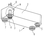
- a domestic water heater 1 has a Plate heat exchanger 2, which is used to heat the contents of the domestic water heater 1 serves.
- This plate heat exchanger 2 is with a heating water inlet 6 and one Provide heating water outlet 7.
- the hot water heater 1 is provided with a cold water inlet 3, which is inside the Domestic water heater 1 is designed as a nozzle 4. Furthermore, the domestic water heater 1 provided with a hot water outlet 5.
- a temperature-dependent resistor 8 (NTC or PTC resistor) arranged close to the hot water heater 1, the a good heat-conducting material is made.
- the NTC resistor 8 is usually activated by means of a control, not shown kept at a certain temperature. If there is a tap of domestic water, cold water then flows in, hitting the one opposite the cold water inlet 3 Wall 9 of the hot water heater 1 and therefore cools the NTC resistor, whereby this changes its resistance value. As a result, a tap is recognized, and the heater, which is formed by the plate heat exchanger 2, is activated.
- the flow rate is incoming cold water too low to the cold water inlet 3 opposite To reach wall 9 of the hot water heater 1, so that the NTC resistor 8 this Inflow of cold water can not capture. This prevents activation of the Heating device, and it also increases the efficiency of the hot water heater reducing start-stop operation of a burner of the heating device, the heated one Water passes through the plate heat exchanger 2 via connections 6 and 7, with short Operating times avoided.
Landscapes
- Engineering & Computer Science (AREA)
- General Engineering & Computer Science (AREA)
- Chemical & Material Sciences (AREA)
- Thermal Sciences (AREA)
- Combustion & Propulsion (AREA)
- Mechanical Engineering (AREA)
- Physics & Mathematics (AREA)
- Instantaneous Water Boilers, Portable Hot-Water Supply Apparatuses, And Control Of Portable Hot-Water Supply Apparatuses (AREA)
- Resistance Heating (AREA)
- Cookers (AREA)
- Thermally Insulated Containers For Foods (AREA)
- Heat-Pump Type And Storage Water Heaters (AREA)
- Sorption Type Refrigeration Machines (AREA)
- Rear-View Mirror Devices That Are Mounted On The Exterior Of The Vehicle (AREA)
Abstract
Description
Claims (3)
- Brauchwasserheizer (1), zum Beispiel Plattenwärmetauscher, mit aus einem gut wärmeleitenden Material hergestellten Wänden, der mit einer Heizeinrichtung versehen ist und einen Kaltwassereinlaß (3) und eine Einrichtung zur Erkennung einer Brauchwasserzapfung aufweist, wobei diese Einrichtung mit einem NTC-Widerstand (8) versehen ist, und mit dem während der Zapfungen zuströmenden Kaltwasser in wärmeleitender Verbindung steht, dadurch gekennzeichnet, daß der NTC-Widerstand (8) im wesentlichen koaxial zum Kaltwassereinlaß (3) an einer diesem gegenüberliegenden Wand (9) des Brauchwasserheizers (1) an deren Außenseite angeordnet ist und mit dieser in gut wärmeleitendem Kontakt steht.
- Brauchwasserheizer nach Anspruch 1, dadurch gekennzeichnet, daß der NTC-Widerstand an dem Brauchwasserheizer (1) dicht anliegt.
- Brauchwasserheizer nach Anspruch 1 oder 2, dadurch gekennzeichnet, daß der Kaltwassereinlauf (3) in den Brauchwassserheizer (1) hineinragt und in dessen Innerem als Düse (4) ausgeformt ist.
Applications Claiming Priority (3)
| Application Number | Priority Date | Filing Date | Title |
|---|---|---|---|
| AT1814/96 | 1996-10-16 | ||
| AT0181496A AT406193B (de) | 1996-10-16 | 1996-10-16 | Brauchwasserheizer |
| AT181496 | 1996-10-16 |
Publications (3)
| Publication Number | Publication Date |
|---|---|
| EP0837287A2 true EP0837287A2 (de) | 1998-04-22 |
| EP0837287A3 EP0837287A3 (de) | 1999-09-08 |
| EP0837287B1 EP0837287B1 (de) | 2003-04-09 |
Family
ID=3521570
Family Applications (1)
| Application Number | Title | Priority Date | Filing Date |
|---|---|---|---|
| EP97250298A Expired - Lifetime EP0837287B1 (de) | 1996-10-16 | 1997-10-09 | Brauchwasserheizer |
Country Status (4)
| Country | Link |
|---|---|
| EP (1) | EP0837287B1 (de) |
| AT (2) | AT406193B (de) |
| DE (2) | DE59709763D1 (de) |
| ES (1) | ES2196259T3 (de) |
Cited By (1)
| Publication number | Priority date | Publication date | Assignee | Title |
|---|---|---|---|---|
| EP1026467A2 (de) | 1999-02-05 | 2000-08-09 | Patente Rehberg Lauer | Plattenwärmeübertrager für Warmwasserbereitung und -speicherung |
Citations (3)
| Publication number | Priority date | Publication date | Assignee | Title |
|---|---|---|---|---|
| DE2756182A1 (de) | 1976-12-17 | 1978-07-27 | Tokyo Shibaura Electric Co | Temperaturregelvorrichtung fuer fluessigkeitsanlagen |
| US4355908A (en) | 1979-02-17 | 1982-10-26 | Battelle-Institut E.V. | Device for measuring the mass flow and the heat flow and method for determining the mass flow |
| DE3910281A1 (de) | 1988-03-30 | 1989-10-12 | Valeo Thermique Moteur Sa | Vorrichtung zur befestigung eines waermeschalters an der wand eines fluid-sammelkastens fuer einen waerme-austauscher |
Family Cites Families (2)
| Publication number | Priority date | Publication date | Assignee | Title |
|---|---|---|---|---|
| AT400080B (de) * | 1989-09-14 | 1995-09-25 | Austria Email Waermetech Gmbh | Warmwasserbereitungsanlage |
| BE1007249A3 (nl) * | 1993-06-24 | 1995-05-02 | Dotraco Nv | Werkwijze voor het regelen van een gekombineerde verwarming en gekombineerde verwarming die deze werkwijze toepast. |
-
1996
- 1996-10-16 AT AT0181496A patent/AT406193B/de not_active IP Right Cessation
-
1997
- 1997-10-09 AT AT97250298T patent/ATE237105T1/de not_active IP Right Cessation
- 1997-10-09 EP EP97250298A patent/EP0837287B1/de not_active Expired - Lifetime
- 1997-10-09 ES ES97250298T patent/ES2196259T3/es not_active Expired - Lifetime
- 1997-10-09 DE DE59709763T patent/DE59709763D1/de not_active Expired - Fee Related
- 1997-10-09 DE DE29718370U patent/DE29718370U1/de not_active Expired - Lifetime
Patent Citations (3)
| Publication number | Priority date | Publication date | Assignee | Title |
|---|---|---|---|---|
| DE2756182A1 (de) | 1976-12-17 | 1978-07-27 | Tokyo Shibaura Electric Co | Temperaturregelvorrichtung fuer fluessigkeitsanlagen |
| US4355908A (en) | 1979-02-17 | 1982-10-26 | Battelle-Institut E.V. | Device for measuring the mass flow and the heat flow and method for determining the mass flow |
| DE3910281A1 (de) | 1988-03-30 | 1989-10-12 | Valeo Thermique Moteur Sa | Vorrichtung zur befestigung eines waermeschalters an der wand eines fluid-sammelkastens fuer einen waerme-austauscher |
Cited By (3)
| Publication number | Priority date | Publication date | Assignee | Title |
|---|---|---|---|---|
| EP1026467A2 (de) | 1999-02-05 | 2000-08-09 | Patente Rehberg Lauer | Plattenwärmeübertrager für Warmwasserbereitung und -speicherung |
| DE19906180A1 (de) * | 1999-02-05 | 2000-08-10 | Peter Rehberg | Plattenwärmeübertrager für Warmwasserbereitung und -speicherung |
| DE19906180C2 (de) * | 1999-02-05 | 2003-02-06 | Peter Rehberg | Plattenwärmeübertrager für Warmwasserbereitung und -speicherung |
Also Published As
| Publication number | Publication date |
|---|---|
| ATA181496A (de) | 1999-07-15 |
| DE59709763D1 (de) | 2003-05-15 |
| AT406193B (de) | 2000-03-27 |
| DE29718370U1 (de) | 1998-01-02 |
| EP0837287A3 (de) | 1999-09-08 |
| EP0837287B1 (de) | 2003-04-09 |
| ES2196259T3 (es) | 2003-12-16 |
| ATE237105T1 (de) | 2003-04-15 |
Similar Documents
| Publication | Publication Date | Title |
|---|---|---|
| DE2635046C2 (de) | Kaffee- oder Teemaschine mit Steigrohr und über einen Bimetall-Springschalter einschaltbarem Durchlauferhitzer | |
| DE3805441C2 (de) | ||
| DE1604071B2 (de) | Anordnung bei einer warmwasserumlaufheizung mit einem im nebenschluss zum heizkreis zwischen vor und ruecklaufleitung eingeschalteten waermeaustauscher fuer gebrauchswasserer hitzung | |
| EP0837287B1 (de) | Brauchwasserheizer | |
| DE69802845T2 (de) | Boiler mit Einrichtung zum Abzapfen von heissem Wasser | |
| DE19860252C1 (de) | Heizeinrichtung für Fahrzeuge | |
| DE19517250A1 (de) | Gasheizgerät | |
| EP0886110B1 (de) | Verfahren zur Brauchwasserbereitstellung in einem kombinierten System | |
| DE3601551C2 (de) | ||
| DE9115237U1 (de) | Heizeinrichtung | |
| DE19636360C2 (de) | Verfahren zur Brauchwasserbereitstellung in einem kombinierten System | |
| DE69200214T2 (de) | Kombinierter Kessel mit Wärmetauscher mit Einbaupumpen. | |
| DE2256769C3 (de) | Warm *asser-Umlaufzentralheizung | |
| DE19820188B4 (de) | Wasserheizer mit einem Schichtenspeicher | |
| DE4006964C2 (de) | ||
| AT406520B (de) | Gasarmatur | |
| DE2344472B2 (de) | Einrichtung zum Steuern eines Brenners | |
| DE29515958U1 (de) | Brauchwasser-Heizeinrichtung | |
| DE1242772B (de) | Elektrischer Durchlauferhitzer mit Druckdifferenzschalter | |
| AT399391B (de) | Brauchwasser-wärmetauscher | |
| CH190367A (de) | Flüssigkeitserhitzer zur Erzeugung von siedendem Wasser. | |
| DE29913297U1 (de) | Schichtenspeicher | |
| DE4429224A1 (de) | Gasheizgerät | |
| DE2153687A1 (de) | Gasbeheizter durchlauf-wassererhitzer | |
| DE29717072U1 (de) | Gasbeheizter Wassererhitzer mit Abgasüberwachungseinrichtung |
Legal Events
| Date | Code | Title | Description |
|---|---|---|---|
| PUAI | Public reference made under article 153(3) epc to a published international application that has entered the european phase |
Free format text: ORIGINAL CODE: 0009012 |
|
| AK | Designated contracting states |
Kind code of ref document: A2 Designated state(s): AT BE CH DE DK ES FR GB IE IT LI LU NL PT SE |
|
| AX | Request for extension of the european patent |
Free format text: AL;LT;LV;RO;SI |
|
| PUAL | Search report despatched |
Free format text: ORIGINAL CODE: 0009013 |
|
| AK | Designated contracting states |
Kind code of ref document: A3 Designated state(s): AT BE CH DE DK ES FI FR GB GR IE IT LI LU MC NL PT SE |
|
| AX | Request for extension of the european patent |
Free format text: AL;LT;LV;RO;SI |
|
| 17P | Request for examination filed |
Effective date: 20000302 |
|
| AKX | Designation fees paid |
Free format text: AT BE CH DE DK ES FR GB IE IT LI LU NL PT SE |
|
| RAP1 | Party data changed (applicant data changed or rights of an application transferred) |
Owner name: VAILLANT GMBH |
|
| GRAH | Despatch of communication of intention to grant a patent |
Free format text: ORIGINAL CODE: EPIDOS IGRA |
|
| GRAH | Despatch of communication of intention to grant a patent |
Free format text: ORIGINAL CODE: EPIDOS IGRA |
|
| GRAA | (expected) grant |
Free format text: ORIGINAL CODE: 0009210 |
|
| AK | Designated contracting states |
Designated state(s): AT BE CH DE DK ES FR GB IE IT LI LU NL PT SE |
|
| PG25 | Lapsed in a contracting state [announced via postgrant information from national office to epo] |
Ref country code: IE Free format text: LAPSE BECAUSE OF NON-PAYMENT OF DUE FEES Effective date: 20030409 |
|
| REG | Reference to a national code |
Ref country code: GB Ref legal event code: FG4D Free format text: NOT ENGLISH |
|
| REG | Reference to a national code |
Ref country code: CH Ref legal event code: EP |
|
| PG25 | Lapsed in a contracting state [announced via postgrant information from national office to epo] |
Ref country code: SE Free format text: LAPSE BECAUSE OF FAILURE TO SUBMIT A TRANSLATION OF THE DESCRIPTION OR TO PAY THE FEE WITHIN THE PRESCRIBED TIME-LIMIT Effective date: 20030709 Ref country code: PT Free format text: LAPSE BECAUSE OF FAILURE TO SUBMIT A TRANSLATION OF THE DESCRIPTION OR TO PAY THE FEE WITHIN THE PRESCRIBED TIME-LIMIT Effective date: 20030709 Ref country code: DK Free format text: LAPSE BECAUSE OF FAILURE TO SUBMIT A TRANSLATION OF THE DESCRIPTION OR TO PAY THE FEE WITHIN THE PRESCRIBED TIME-LIMIT Effective date: 20030709 |
|
| GBT | Gb: translation of ep patent filed (gb section 77(6)(a)/1977) | ||
| PG25 | Lapsed in a contracting state [announced via postgrant information from national office to epo] |
Ref country code: LU Free format text: LAPSE BECAUSE OF NON-PAYMENT OF DUE FEES Effective date: 20031009 |
|
| REG | Reference to a national code |
Ref country code: IE Ref legal event code: FD4D Ref document number: 0837287E Country of ref document: IE |
|
| REG | Reference to a national code |
Ref country code: ES Ref legal event code: FG2A Ref document number: 2196259 Country of ref document: ES Kind code of ref document: T3 |
|
| PGFP | Annual fee paid to national office [announced via postgrant information from national office to epo] |
Ref country code: BE Payment date: 20040119 Year of fee payment: 7 |
|
| ET | Fr: translation filed | ||
| PLBE | No opposition filed within time limit |
Free format text: ORIGINAL CODE: 0009261 |
|
| STAA | Information on the status of an ep patent application or granted ep patent |
Free format text: STATUS: NO OPPOSITION FILED WITHIN TIME LIMIT |
|
| 26N | No opposition filed |
Effective date: 20040112 |
|
| PG25 | Lapsed in a contracting state [announced via postgrant information from national office to epo] |
Ref country code: BE Free format text: LAPSE BECAUSE OF NON-PAYMENT OF DUE FEES Effective date: 20041031 |
|
| BERE | Be: lapsed |
Owner name: *VAILLANT G.M.B.H. Effective date: 20041031 |
|
| BERE | Be: lapsed |
Owner name: *VAILLANT G.M.B.H. Effective date: 20041031 |
|
| PGFP | Annual fee paid to national office [announced via postgrant information from national office to epo] |
Ref country code: DE Payment date: 20071029 Year of fee payment: 11 |
|
| PGFP | Annual fee paid to national office [announced via postgrant information from national office to epo] |
Ref country code: ES Payment date: 20080926 Year of fee payment: 12 |
|
| PGFP | Annual fee paid to national office [announced via postgrant information from national office to epo] |
Ref country code: NL Payment date: 20081031 Year of fee payment: 12 Ref country code: FR Payment date: 20080905 Year of fee payment: 12 |
|
| PGFP | Annual fee paid to national office [announced via postgrant information from national office to epo] |
Ref country code: GB Payment date: 20080911 Year of fee payment: 12 |
|
| PGFP | Annual fee paid to national office [announced via postgrant information from national office to epo] |
Ref country code: CH Payment date: 20081015 Year of fee payment: 12 |
|
| PGFP | Annual fee paid to national office [announced via postgrant information from national office to epo] |
Ref country code: AT Payment date: 20080908 Year of fee payment: 12 |
|
| PGFP | Annual fee paid to national office [announced via postgrant information from national office to epo] |
Ref country code: IT Payment date: 20081022 Year of fee payment: 12 |
|
| PG25 | Lapsed in a contracting state [announced via postgrant information from national office to epo] |
Ref country code: DE Free format text: LAPSE BECAUSE OF NON-PAYMENT OF DUE FEES Effective date: 20090501 |
|
| REG | Reference to a national code |
Ref country code: NL Ref legal event code: V1 Effective date: 20100501 |
|
| REG | Reference to a national code |
Ref country code: CH Ref legal event code: PL |
|
| REG | Reference to a national code |
Ref country code: FR Ref legal event code: ST Effective date: 20100630 |
|
| PG25 | Lapsed in a contracting state [announced via postgrant information from national office to epo] |
Ref country code: NL Free format text: LAPSE BECAUSE OF NON-PAYMENT OF DUE FEES Effective date: 20100501 Ref country code: FR Free format text: LAPSE BECAUSE OF NON-PAYMENT OF DUE FEES Effective date: 20091102 |
|
| PG25 | Lapsed in a contracting state [announced via postgrant information from national office to epo] |
Ref country code: AT Free format text: LAPSE BECAUSE OF NON-PAYMENT OF DUE FEES Effective date: 20091009 |
|
| PG25 | Lapsed in a contracting state [announced via postgrant information from national office to epo] |
Ref country code: LI Free format text: LAPSE BECAUSE OF NON-PAYMENT OF DUE FEES Effective date: 20091031 Ref country code: CH Free format text: LAPSE BECAUSE OF NON-PAYMENT OF DUE FEES Effective date: 20091031 |
|
| PG25 | Lapsed in a contracting state [announced via postgrant information from national office to epo] |
Ref country code: GB Free format text: LAPSE BECAUSE OF NON-PAYMENT OF DUE FEES Effective date: 20091009 |
|
| REG | Reference to a national code |
Ref country code: ES Ref legal event code: FD2A Effective date: 20110309 |
|
| PG25 | Lapsed in a contracting state [announced via postgrant information from national office to epo] |
Ref country code: IT Free format text: LAPSE BECAUSE OF NON-PAYMENT OF DUE FEES Effective date: 20091009 |
|
| PG25 | Lapsed in a contracting state [announced via postgrant information from national office to epo] |
Ref country code: ES Free format text: LAPSE BECAUSE OF NON-PAYMENT OF DUE FEES Effective date: 20110308 |
|
| PG25 | Lapsed in a contracting state [announced via postgrant information from national office to epo] |
Ref country code: ES Free format text: LAPSE BECAUSE OF NON-PAYMENT OF DUE FEES Effective date: 20091010 |