EP0837384A2 - Mallette de transport pour système informatique - Google Patents
Mallette de transport pour système informatique Download PDFInfo
- Publication number
- EP0837384A2 EP0837384A2 EP97115862A EP97115862A EP0837384A2 EP 0837384 A2 EP0837384 A2 EP 0837384A2 EP 97115862 A EP97115862 A EP 97115862A EP 97115862 A EP97115862 A EP 97115862A EP 0837384 A2 EP0837384 A2 EP 0837384A2
- Authority
- EP
- European Patent Office
- Prior art keywords
- printer
- carrying case
- partition
- case according
- support plate
- Prior art date
- Legal status (The legal status is an assumption and is not a legal conclusion. Google has not performed a legal analysis and makes no representation as to the accuracy of the status listed.)
- Granted
Links
Images


Classifications
-
- A—HUMAN NECESSITIES
- A45—HAND OR TRAVELLING ARTICLES
- A45C—PURSES; LUGGAGE; HAND CARRIED BAGS
- A45C5/00—Rigid or semi-rigid luggage
-
- A—HUMAN NECESSITIES
- A45—HAND OR TRAVELLING ARTICLES
- A45C—PURSES; LUGGAGE; HAND CARRIED BAGS
- A45C13/00—Details; Accessories
- A45C13/02—Interior fittings; Means, e.g. inserts, for holding and packing articles
-
- G—PHYSICS
- G06—COMPUTING OR CALCULATING; COUNTING
- G06F—ELECTRIC DIGITAL DATA PROCESSING
- G06F1/00—Details not covered by groups G06F3/00 - G06F13/00 and G06F21/00
- G06F1/16—Constructional details or arrangements
- G06F1/1613—Constructional details or arrangements for portable computers
- G06F1/1628—Enclosures for carrying portable computers with peripheral devices, e.g. cases for a laptop and a printer
-
- A—HUMAN NECESSITIES
- A45—HAND OR TRAVELLING ARTICLES
- A45C—PURSES; LUGGAGE; HAND CARRIED BAGS
- A45C13/00—Details; Accessories
- A45C13/02—Interior fittings; Means, e.g. inserts, for holding and packing articles
- A45C2013/025—Interior fittings; Means, e.g. inserts, for holding and packing articles for holding portable computers or accessories therefor
-
- A—HUMAN NECESSITIES
- A45—HAND OR TRAVELLING ARTICLES
- A45C—PURSES; LUGGAGE; HAND CARRIED BAGS
- A45C3/00—Flexible luggage; Handbags
Definitions
- the invention relates to a carrying case such as suitcase, bag or the like for a portable computer, a printer and accessories according to the preamble of claim 1.
- Portable computers are characterized above all by their mobile usability from what the wish derives, suitable Carrying cases for the computer, the associated Printers and the accessories necessary for their operation to have available.
- a two-shell suitcase in whose bottom part compartments are accommodated for reception the power supply, the cables and the individual Devices while the lid part is closed the case protects these parts and, if necessary, still receiving pockets for paper, documents, writing utensils or the like. houses.
- the case is handled itself so that its cover part is removed from the bottom part and this one with all of it Equipment is placed on the work table so that can be worked on the computer. This requires on the work table has a relatively large work surface and is also used for other reasons, e.g. because of the total weight this unity, found to be disturbing.
- a case known from DE 93 19 685 U1 has a base frame, two side walls, a front wall and a rear wall and on its upper side a hinged lid for closing the case.
- Inside the case there are several storage compartments, in particular one for the computer and one for the printer.
- the front wall is hinged to the bottom frame about a horizontal axis lying below and can be folded down from the vertical into a tilt position of about 45 o after the shell-like case lid has been opened.
- the computer When the front wall is unfolded, the computer partially swings out of the interior of the carrying case and can thus be removed better than when the front wall is vertical.
- the storage compartment for the computer is bounded on the one hand by the fold-out front wall and on the other hand by a partition wall, on the side of which facing away from the computer is arranged further inside in the carrying case of the printer.
- This partition consists of a plate inserted into side brackets and a bowl-like pressure support body, the bottom of which is hinged to the plate via hinges. If the case lid is open, the front wall is unfolded and the computer is removed, the printer support body can also be folded forward and partially out of the interior of the container by about 90 o until its bottom meets supports that are specially attached to the inside of the front wall. The printer is in this operating position ready so that when the carrying case is on the floor it can be operated by the seated computer user, provided he leans forward and downward enough.
- the pressure support body is designed as a plate, which can be swiveled along a horizontal axis the upper edge of a partition part is connected.
- the both vertically displaceable in side guides Plates can be pulled out a little upwards. Once the printer support plate out of the guides is released, it can with the printer attached to it from its vertical storage position into a horizontal one Use position be flipped.
- the folded printer support plate is here also with the involvement of Front wall of the case supported in the printer operating position, but in a special way on an apex area, the one with the container open fixed, lower front wall part and one around a horizontal Foldable axis on this articulated upper Front wall part is formed.
- DE 195 06 740 C2 relates to a carrying case for a printer that is kept upright when stowed and transported and in an elevated position horizontally is operated.
- a special problem with the very advantageous means according to patent DE 195 06 740 C2 alone cannot be controlled, throw however, printers that are upright even in the operator position stand.
- a prominent example of this is the Printer type HP 340 of the 'DeskJet' family of the American Manufacturing company Hewlett Packard.
- a single sheet feeder can be attached, while in the ground, the now opposite Side wall, a slit-shaped paper ejection located.
- the preferred stowage location for any printer is because the optimal use of space always an upright or Upright, but a printer of this type is said to be also from its stowed position in the carrying case into a raised operating position, but must not be thrown.
- DE 296 01 928 U1 is a carrying case known that trained in a clever way is that in operation, printers standing upright in ergonomic favorable allocation to the carrying case or Position of the seated user can be operated safely can.
- the object of the present invention is now that Provision of a universal solution for a generic Carrying case that is both for horizontal as well as vertically operated printers alike suitable is.
- the invention is particularly characterized characterized in that the partition is formed in one piece and in its entirety forms the pressure support plate, that defines the pivot axis of the journal is above the partition edges in the side guides engage and that the Swivel axis at a distance from the lower or rear Partition edge is arranged.
- the now one-piece printer support plate can be due to missing joint connections of the two-part so far Execution to be more stable overall. At the same time is the total area of the printer support plate enlarged so that any portable small printer a most suitable place on this one Can find area. Due to the special arrangement of the Swivel axis at a distance from the bottom (in the stowed position) or (in the operating position) rear partition edge is achieved that the printer support plate in the Operating position of the printer also to the inner area of the Carrying case towards the rear wall can extend and consequently not in statically unfavorable Point too far forward out of the carrying case protrudes.
- a surface zip one made of fleece tape and hook tape existing Velcro.
- separable fastening means also called Velcro pads can also be stowed vertically in one as well as vertically operable printers, whereby additionally by means of a hinge arrangement between Printer and printer support plate ensure that, while the printer is in its vertical position, which it stows occupies, even in the operating position, albeit at a higher level of work that maintains Printer support plate from the vertical printer storage position to a horizontal printer standby can be pivoted.
- the printer operating position can be from the stowed position swung out as a partition in the printer operating position Printer support plate itself on the crown area first, fixed and a second, outward hinged front wall part of the carrying case support, as it is already in principle DE 195 06 740 C2 and shown in DE 296 01 928 U1 and is described.
- the partition as a swung out pressure support plate - preferably automatic - lockable in the printer operating position should be. This is achieved by everyone Carrying an insertion pocket for the axle journal is assigned to a support bracket under it. After pulling up and swiveling, you need the Printer support plate with its axle journals then only - e.g. to the rear - inserted into these pockets to be safely intercepted in the vertical direction and to be stored.
- This handling can be simplified Secured by the fact that in the movement path of the journal a limit stop engages in the pull-out direction, that for a correct allocation of the insert pocket provides without special attention of the user is required.
- the control link can in turn be a control surface for the control pin that will be assigned towards the end the pivoting movement of the partition on its journal the support column guides. This is how it works Relocate the partition from the transport position as Printer support plate in the printer operating position after simple principle of seeing and using. For it nothing needs to be done other than with the partition grasp the printer, pull up and swivel forward until the usable and immediately locked position for the printer automatically is reached.
- the printer support plate in the printer use position can Control link a support surface for the control pin be assigned in the operating position of the partition, so that the printer support plate in the area of the - then rear - Control pin also safe in the vertical direction is supported.
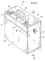
- FIG. 1 The example shown in Fig. 1 and in is in its entirety designated 10 carrying case designed like a pilot's case. It includes a floor, possibly also designed as a frame body 11, a rear wall 12, further two opposite one another Side walls 13 (in cases of the illustrated Art also called 'wedges'), and a front wall 14 and a two-part, from an inner lid flap 15 and an external part of this Cover part 16 existing closure arrangement.
- a floor possibly also designed as a frame body 11
- a rear wall 12 further two opposite one another Side walls 13 (in cases of the illustrated Art also called 'wedges')
- a front wall 14 and a two-part from an inner lid flap 15 and an external part of this Cover part 16 existing closure arrangement.
- the inner lid flap 15 has two Locks 17 and a pivoting handle 18, and the outside cover lid flap 16 'two Lock bolt 19 and an opening 20 for the penetration of the handle 18. Finally, at 21 are on the Side walls 13 attached brackets for removable if necessary Plug in a not shown Carrying strap designated.
- the front wall 14 is divided into a lower, fixed front wall part 22 and an upper to a horizontal axis 23 pivotable front wall part 24.
- the heights of the fixed front wall part 22 and of the movable front wall part 24 add up - approximately in the ratio 4/1 - to the total height of the carrying case 10.
- the upper movable front wall part 24 the connection between the fixed Front wall parts 22 and the inner lid flap 15 forth, the lid flap 15 and the front wall part 24 (at right angles to each other) rigid or - and although preferably as in the illustrated embodiment - About one in the closed state of the container case edge forming fold 55 or hinge can be movably connected.
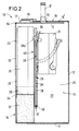
- FIG. 2 serves the interior of the container 25 to accommodate numerous for the operation of a portable computer, in particular a notebook or a rare one Laptops, suitable recordings.
- a portable computer in particular a notebook or a rare one Laptops, suitable recordings.
- partition 26 Through a vertical, longitudinally largely through the interior 25 of the case-like carrying case 10 extending partition 26 is a receiving space 28 for the front wall a computer 29 and then a recording room 30 created for a printer 31.
- Printer 31 in the manner described below in the stowed position shown in FIG. 2 or FIG. 6 are allowed on the basis of the usual today miniaturized construction the arrangement of further objects, so e.g. a power supply in the same compartment 30 below the respective printer 31. Also Printer cable, not shown, a mouse and the like. to let stow away there.
- Receiving compartment 28 To adapt the limited by the front wall 14 Receiving compartment 28 to the individual size of certain Brands or types of computers 29 are two molded articles 32 of substantially L-shaped basic shape as Adapter inserts provided. These are in the bottom Corners of the receiving compartment 28 inserted such that the computer 29 with its lower corner regions 33 each rests on a horizontal leg 34 and laterally stabilized by the vertical legs 35 is held in the receiving compartment 28. Should that Carrying case 10 for storing a computer 29 different sizes are used, the adapter inserts 32 exchanged for those of a different dimension. Incidentally, they are simple parts made of plastic, e.g. Foam.
- the partition 26, the receiving space 28 for the Computer 29 against the receiving space 30 for the printer 31 compartments, is as a one-piece and one-piece plate 36 executed.
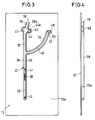
- the plate 36 has on each long side at a distance from their lower edge 37 each axially extending axles 38 on a vertical section 39 of a Guide 40 can slide. In each of the carrying sidewalls 13 associated guide 30 engages only one such journal 38, but not the plate 36 itself.
- a first peculiarity is that in the Movement path of each of the axle journals in the pull-out direction (Arrow 41) engages a limit stop 42 and a second in that the guide 40 has an insertion pocket 43 for the journal 39 with an underpinning Support bracket 44 and one overlapping it Shoulder 44a is assigned.
- control pin 45 one at the bottom of each Plate 36 from the same edge as the journal 38 and protrudes parallel to them, into the opening area an arcuate control link 46.
- This control link 46 guides the control pin 45 during the pivoting the plate 36 by about 90 °.
- the end area the control link 46 is a substantially arcuate-oblique extending control surface 47 and, thereon then, a pocket 48 closed at the end assigned.
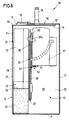
- a printer 31 continues in its operating position in front, as appropriate, the one to be operated horizontally Printer 31 in Fig. 5 or further back on the as Printing support plate 27 serving plate 36 rests like that printer 31 to be operated vertically in accordance with FIG. 7: Every printer finds its typical, without prejudice Operating position on the printer support plate 27 one against another Swiveled or swiveled back and locked accordingly stable position.
- the apex region 49 can be between the fixed lower front wall part 22 and the hinged upper front wall part 24 of the carrying case 10 also, and preferably in addition, the support serve the printer support plate 27.
- the support serve the printer support plate 27.
- a horizontally operable printer 31 can by means of self-adhesive surface fastener elements 51 (Velcro pads) firmly, although removable, immediately be attached to the printer support plate 27. Since the Partition / pressure support plate 26/27 with respect to one vertical operable printer 31 according to FIGS. 6 and 7 when changing from its stowed position (Fig. 6) in the Ready position (Fig. 7) and vice versa a relative Such a movement must be carried out Printer 31 by means of a hinge strap 52 for Swivel axis of the partition / pressure support plate 26/27 parallel pivot axis 53 attached.
- the hinge strap 52 is then preferred by means of double-sided adhesive tape strips attached to the partition / pressure support plate 26/27 and the printer 31 by means of the Velcro tape pads 51 detachably attached to the second hinge strip.
- the hinge strap 52 can be used as a plastic injection molded part with uniform hinge axis 53 e.g. formed in the form of a film hinge be.
- a spacing pad 54 e.g. a Foam cushion
- Velcro pads 51 are also provided here, one part of which is self-adhesive under the Printer 31 and the respective other part self-adhesive is attached to the pad 54.
- the partition / printer support plate 26/27 prepared at the factory be by equipping them with the appropriate required parts of fasteners 51 to 54.
- Um to leave the user free to choose the fastening parts 51 to 54 can also be made in total the carrying case for individual furnishing in Matched to the printer 31 used be.
Landscapes
- Engineering & Computer Science (AREA)
- Theoretical Computer Science (AREA)
- Physics & Mathematics (AREA)
- Human Computer Interaction (AREA)
- General Engineering & Computer Science (AREA)
- General Physics & Mathematics (AREA)
- Computer Hardware Design (AREA)
- Accessory Devices And Overall Control Thereof (AREA)
- Purses, Travelling Bags, Baskets, Or Suitcases (AREA)
- Telephonic Communication Services (AREA)
- Measuring Pulse, Heart Rate, Blood Pressure Or Blood Flow (AREA)
- Iron Core Of Rotating Electric Machines (AREA)
- Printers Characterized By Their Purpose (AREA)
Applications Claiming Priority (2)
| Application Number | Priority Date | Filing Date | Title |
|---|---|---|---|
| DE19643040A DE19643040C1 (de) | 1996-10-18 | 1996-10-18 | EDV-System-Koffer |
| DE19643040 | 1996-10-18 |
Publications (3)
| Publication Number | Publication Date |
|---|---|
| EP0837384A2 true EP0837384A2 (fr) | 1998-04-22 |
| EP0837384A3 EP0837384A3 (fr) | 1998-04-29 |
| EP0837384B1 EP0837384B1 (fr) | 2003-01-15 |
Family
ID=7809117
Family Applications (1)
| Application Number | Title | Priority Date | Filing Date |
|---|---|---|---|
| EP97115862A Expired - Lifetime EP0837384B1 (fr) | 1996-10-18 | 1997-09-12 | Mallette de transport pour système informatique |
Country Status (5)
| Country | Link |
|---|---|
| EP (1) | EP0837384B1 (fr) |
| AT (1) | ATE231253T1 (fr) |
| DE (2) | DE19643040C1 (fr) |
| DK (1) | DK0837384T3 (fr) |
| ES (1) | ES2188837T3 (fr) |
Cited By (3)
| Publication number | Priority date | Publication date | Assignee | Title |
|---|---|---|---|---|
| EP1238601A1 (fr) * | 2001-03-09 | 2002-09-11 | Orlan Holding S.A. | Attaché-case particulièrement adapté pour transporter un ordinateur portable et ses accessoires |
| EP1255181A3 (fr) * | 2001-04-23 | 2004-01-21 | Winfo Data GmbH | Dispositif d'escamotage pour escamoter des appareils électriques dans des unités mobiles |
| CN103275561A (zh) * | 2013-05-22 | 2013-09-04 | 袁伟 | 一种环保水性纳米色浆及其制备方法 |
Families Citing this family (3)
| Publication number | Priority date | Publication date | Assignee | Title |
|---|---|---|---|---|
| WO1999055189A2 (fr) | 1998-04-24 | 1999-11-04 | Mp Michael Pfeiffer Design & Marketing Gmbh | Valise |
| DE29807481U1 (de) * | 1998-04-24 | 1999-09-02 | MP Michael Pfeiffer Design & Marketing GmbH, 85649 Brunnthal | Rollenkoffer |
| DE10310890B4 (de) * | 2003-03-11 | 2008-01-31 | PARAT-Werk Schönenbach GmbH + Co. KG | Vorrichtung zur Halterung eines Geräts auf einer Platte, insbesondere eines Druckers auf einem in einer Tragetasche, einem Koffer o. dgl. anzuordnenden Druckertableau |
Family Cites Families (4)
| Publication number | Priority date | Publication date | Assignee | Title |
|---|---|---|---|---|
| DE9319685U1 (de) * | 1993-12-21 | 1994-04-07 | Felke, Bernhard, 83026 Rosenheim | Kofferähnlicher Behälter zur Aufnahme von mobilen Datenverarbeitungsgeräten |
| DE19506740C1 (de) * | 1995-02-27 | 1996-04-25 | Parat Werk Schoenenbach Gmbh | EDV-System-Koffer |
| DE29601928U1 (de) * | 1996-02-07 | 1996-04-11 | PARAT-Werk Schönenbach GmbH + Co KG, 42897 Remscheid | EDV-System-Koffer |
| DE29618106U1 (de) * | 1996-10-18 | 1996-12-12 | PARAT-Werk Schönenbach GmbH + Co KG, 42897 Remscheid | EDV-System-Koffer |
-
1996
- 1996-10-18 DE DE19643040A patent/DE19643040C1/de not_active Expired - Fee Related
-
1997
- 1997-09-12 EP EP97115862A patent/EP0837384B1/fr not_active Expired - Lifetime
- 1997-09-12 DK DK97115862T patent/DK0837384T3/da active
- 1997-09-12 ES ES97115862T patent/ES2188837T3/es not_active Expired - Lifetime
- 1997-09-12 DE DE59709138T patent/DE59709138D1/de not_active Expired - Fee Related
- 1997-09-12 AT AT97115862T patent/ATE231253T1/de not_active IP Right Cessation
Cited By (4)
| Publication number | Priority date | Publication date | Assignee | Title |
|---|---|---|---|---|
| EP1238601A1 (fr) * | 2001-03-09 | 2002-09-11 | Orlan Holding S.A. | Attaché-case particulièrement adapté pour transporter un ordinateur portable et ses accessoires |
| EP1255181A3 (fr) * | 2001-04-23 | 2004-01-21 | Winfo Data GmbH | Dispositif d'escamotage pour escamoter des appareils électriques dans des unités mobiles |
| CN103275561A (zh) * | 2013-05-22 | 2013-09-04 | 袁伟 | 一种环保水性纳米色浆及其制备方法 |
| CN103275561B (zh) * | 2013-05-22 | 2015-06-03 | 袁伟 | 一种环保水性纳米色浆及其制备方法 |
Also Published As
| Publication number | Publication date |
|---|---|
| DK0837384T3 (da) | 2003-02-24 |
| EP0837384B1 (fr) | 2003-01-15 |
| EP0837384A3 (fr) | 1998-04-29 |
| DE59709138D1 (de) | 2003-02-20 |
| DE19643040C1 (de) | 1998-04-23 |
| ES2188837T3 (es) | 2003-07-01 |
| ATE231253T1 (de) | 2003-02-15 |
Similar Documents
| Publication | Publication Date | Title |
|---|---|---|
| EP0772411A1 (fr) | Poste de travail | |
| DE202015000254U1 (de) | Koffer, insbesondere Pilotenkoffer | |
| DE20014050U1 (de) | System zur Unterbringung von Ladegut in einem Fahrzeug | |
| EP0837384B1 (fr) | Mallette de transport pour système informatique | |
| EP0008687A1 (fr) | Table de machine à coudre avec dispositif d'escamotage | |
| DE19506740C1 (de) | EDV-System-Koffer | |
| DE10153492A1 (de) | Tisch, insbesondere Schülertisch | |
| DE29503256U1 (de) | EDV-System-Koffer | |
| DE29618106U1 (de) | EDV-System-Koffer | |
| DE19604407C2 (de) | EDV-System-Koffer | |
| DE29821711U1 (de) | Mobile Computereinheit | |
| WO2018177637A1 (fr) | Contenant de transport | |
| DE29601928U1 (de) | EDV-System-Koffer | |
| EP0758110B1 (fr) | Mallette de transport pour système informatique | |
| DE202005003818U1 (de) | Koffer | |
| DE10331071B4 (de) | Computerarbeitsplatz in einem Fahrzeug, insbesondere in einer Großraumlimousine | |
| DE102025127623A1 (de) | Aufbewahrungsfach, das benachbart zu einer pritschenseitenstufe angeordnet ist | |
| DE102007012215B4 (de) | Vorrichtung zum Transport von Stückgut | |
| DE19837725C1 (de) | Abfallsammler zum Einbau in ein Schrankmöbel | |
| DE202010008188U1 (de) | Transportabler Container in Kofferform | |
| DE9209585U1 (de) | Nähmöbel | |
| DE102012214653A1 (de) | Anordnung aus einem Sideboard und einem Tisch | |
| DE929847C (de) | Einrichtung fuer Behaelter von Sichtkarteien | |
| DE202019005120U1 (de) | Messetrolley | |
| DE8626495U1 (de) | Büromöbel in Form einer Anrichte |
Legal Events
| Date | Code | Title | Description |
|---|---|---|---|
| PUAI | Public reference made under article 153(3) epc to a published international application that has entered the european phase |
Free format text: ORIGINAL CODE: 0009012 |
|
| PUAL | Search report despatched |
Free format text: ORIGINAL CODE: 0009013 |
|
| AK | Designated contracting states |
Kind code of ref document: A2 Designated state(s): AT BE CH DE DK ES FI FR GB IE IT LI LU NL SE |
|
| AX | Request for extension of the european patent |
Free format text: AL;LT;LV;RO;SI |
|
| AK | Designated contracting states |
Kind code of ref document: A3 Designated state(s): AT BE CH DE DK ES FI FR GB GR IE IT LI LU MC NL PT SE |
|
| AX | Request for extension of the european patent |
Free format text: AL;LT;LV;RO;SI |
|
| 17P | Request for examination filed |
Effective date: 19980518 |
|
| AKX | Designation fees paid |
Free format text: AT BE CH DE DK ES FI FR GB GR IE IT LI LU |
|
| RBV | Designated contracting states (corrected) |
Designated state(s): AT BE CH DE DK ES FI FR GB GR IE IT LI LU |
|
| RBV | Designated contracting states (corrected) |
Designated state(s): AT BE CH DE DK ES FI FR GB IE IT LI LU NL SE |
|
| GRAG | Despatch of communication of intention to grant |
Free format text: ORIGINAL CODE: EPIDOS AGRA |
|
| 17Q | First examination report despatched |
Effective date: 20020228 |
|
| GRAG | Despatch of communication of intention to grant |
Free format text: ORIGINAL CODE: EPIDOS AGRA |
|
| GRAH | Despatch of communication of intention to grant a patent |
Free format text: ORIGINAL CODE: EPIDOS IGRA |
|
| GRAH | Despatch of communication of intention to grant a patent |
Free format text: ORIGINAL CODE: EPIDOS IGRA |
|
| GRAA | (expected) grant |
Free format text: ORIGINAL CODE: 0009210 |
|
| AK | Designated contracting states |
Kind code of ref document: B1 Designated state(s): AT BE CH DE DK ES FI FR GB IE IT LI LU NL SE |
|
| REG | Reference to a national code |
Ref country code: GB Ref legal event code: FG4D Free format text: NOT ENGLISH Ref country code: CH Ref legal event code: EP |
|
| REG | Reference to a national code |
Ref country code: IE Ref legal event code: FG4D Free format text: GERMAN |
|
| REF | Corresponds to: |
Ref document number: 59709138 Country of ref document: DE Date of ref document: 20030220 Kind code of ref document: P |
|
| REG | Reference to a national code |
Ref country code: DK Ref legal event code: T3 |
|
| REG | Reference to a national code |
Ref country code: CH Ref legal event code: NV Representative=s name: MOINAS & SAVOYE SA |
|
| GBT | Gb: translation of ep patent filed (gb section 77(6)(a)/1977) |
Effective date: 20030415 |
|
| ET | Fr: translation filed | ||
| REG | Reference to a national code |
Ref country code: ES Ref legal event code: FG2A Ref document number: 2188837 Country of ref document: ES Kind code of ref document: T3 |
|
| PGFP | Annual fee paid to national office [announced via postgrant information from national office to epo] |
Ref country code: IE Payment date: 20030905 Year of fee payment: 7 |
|
| PGFP | Annual fee paid to national office [announced via postgrant information from national office to epo] |
Ref country code: LU Payment date: 20030917 Year of fee payment: 7 |
|
| PLBE | No opposition filed within time limit |
Free format text: ORIGINAL CODE: 0009261 |
|
| STAA | Information on the status of an ep patent application or granted ep patent |
Free format text: STATUS: NO OPPOSITION FILED WITHIN TIME LIMIT |
|
| 26N | No opposition filed |
Effective date: 20031016 |
|
| PG25 | Lapsed in a contracting state [announced via postgrant information from national office to epo] |
Ref country code: LU Free format text: LAPSE BECAUSE OF NON-PAYMENT OF DUE FEES Effective date: 20040912 |
|
| PG25 | Lapsed in a contracting state [announced via postgrant information from national office to epo] |
Ref country code: IE Free format text: LAPSE BECAUSE OF NON-PAYMENT OF DUE FEES Effective date: 20040913 |
|
| REG | Reference to a national code |
Ref country code: IE Ref legal event code: MM4A |
|
| PGFP | Annual fee paid to national office [announced via postgrant information from national office to epo] |
Ref country code: GB Payment date: 20050915 Year of fee payment: 9 Ref country code: FR Payment date: 20050915 Year of fee payment: 9 |
|
| PGFP | Annual fee paid to national office [announced via postgrant information from national office to epo] |
Ref country code: SE Payment date: 20050920 Year of fee payment: 9 |
|
| PGFP | Annual fee paid to national office [announced via postgrant information from national office to epo] |
Ref country code: FI Payment date: 20050921 Year of fee payment: 9 Ref country code: ES Payment date: 20050921 Year of fee payment: 9 Ref country code: DK Payment date: 20050921 Year of fee payment: 9 |
|
| PGFP | Annual fee paid to national office [announced via postgrant information from national office to epo] |
Ref country code: BE Payment date: 20050928 Year of fee payment: 9 Ref country code: AT Payment date: 20050928 Year of fee payment: 9 |
|
| PGFP | Annual fee paid to national office [announced via postgrant information from national office to epo] |
Ref country code: NL Payment date: 20050930 Year of fee payment: 9 |
|
| PGFP | Annual fee paid to national office [announced via postgrant information from national office to epo] |
Ref country code: DE Payment date: 20051101 Year of fee payment: 9 |
|
| PG25 | Lapsed in a contracting state [announced via postgrant information from national office to epo] |
Ref country code: FI Free format text: LAPSE BECAUSE OF NON-PAYMENT OF DUE FEES Effective date: 20060912 Ref country code: AT Free format text: LAPSE BECAUSE OF NON-PAYMENT OF DUE FEES Effective date: 20060912 |
|
| PG25 | Lapsed in a contracting state [announced via postgrant information from national office to epo] |
Ref country code: SE Free format text: LAPSE BECAUSE OF NON-PAYMENT OF DUE FEES Effective date: 20060913 |
|
| PG25 | Lapsed in a contracting state [announced via postgrant information from national office to epo] |
Ref country code: BE Free format text: LAPSE BECAUSE OF NON-PAYMENT OF DUE FEES Effective date: 20060930 |
|
| PGFP | Annual fee paid to national office [announced via postgrant information from national office to epo] |
Ref country code: IT Payment date: 20060930 Year of fee payment: 10 |
|
| PG25 | Lapsed in a contracting state [announced via postgrant information from national office to epo] |
Ref country code: DK Free format text: LAPSE BECAUSE OF NON-PAYMENT OF DUE FEES Effective date: 20061002 |
|
| PG25 | Lapsed in a contracting state [announced via postgrant information from national office to epo] |
Ref country code: NL Free format text: LAPSE BECAUSE OF NON-PAYMENT OF DUE FEES Effective date: 20070401 |
|
| PG25 | Lapsed in a contracting state [announced via postgrant information from national office to epo] |
Ref country code: DE Free format text: LAPSE BECAUSE OF NON-PAYMENT OF DUE FEES Effective date: 20070403 |
|
| REG | Reference to a national code |
Ref country code: DK Ref legal event code: EBP |
|
| EUG | Se: european patent has lapsed | ||
| GBPC | Gb: european patent ceased through non-payment of renewal fee |
Effective date: 20060912 |
|
| NLV4 | Nl: lapsed or anulled due to non-payment of the annual fee |
Effective date: 20070401 |
|
| REG | Reference to a national code |
Ref country code: FR Ref legal event code: ST Effective date: 20070531 |
|
| PG25 | Lapsed in a contracting state [announced via postgrant information from national office to epo] |
Ref country code: GB Free format text: LAPSE BECAUSE OF NON-PAYMENT OF DUE FEES Effective date: 20060912 |
|
| REG | Reference to a national code |
Ref country code: ES Ref legal event code: FD2A Effective date: 20060913 |
|
| BERE | Be: lapsed |
Owner name: *PARAT-WERK SCHONENBACH G.M.B.H. + CO. K.G. Effective date: 20060930 |
|
| PG25 | Lapsed in a contracting state [announced via postgrant information from national office to epo] |
Ref country code: ES Free format text: LAPSE BECAUSE OF NON-PAYMENT OF DUE FEES Effective date: 20060913 |
|
| PGFP | Annual fee paid to national office [announced via postgrant information from national office to epo] |
Ref country code: CH Payment date: 20071002 Year of fee payment: 11 |
|
| PG25 | Lapsed in a contracting state [announced via postgrant information from national office to epo] |
Ref country code: FR Free format text: LAPSE BECAUSE OF NON-PAYMENT OF DUE FEES Effective date: 20061002 |
|
| REG | Reference to a national code |
Ref country code: CH Ref legal event code: PL |
|
| PG25 | Lapsed in a contracting state [announced via postgrant information from national office to epo] |
Ref country code: IT Free format text: LAPSE BECAUSE OF NON-PAYMENT OF DUE FEES Effective date: 20070912 |
|
| PG25 | Lapsed in a contracting state [announced via postgrant information from national office to epo] |
Ref country code: LI Free format text: LAPSE BECAUSE OF NON-PAYMENT OF DUE FEES Effective date: 20080930 Ref country code: CH Free format text: LAPSE BECAUSE OF NON-PAYMENT OF DUE FEES Effective date: 20080930 |