EP0837552A2 - Notbetriebssteuerung für ein Hebezeug - Google Patents
Notbetriebssteuerung für ein Hebezeug Download PDFInfo
- Publication number
- EP0837552A2 EP0837552A2 EP97117520A EP97117520A EP0837552A2 EP 0837552 A2 EP0837552 A2 EP 0837552A2 EP 97117520 A EP97117520 A EP 97117520A EP 97117520 A EP97117520 A EP 97117520A EP 0837552 A2 EP0837552 A2 EP 0837552A2
- Authority
- EP
- European Patent Office
- Prior art keywords
- microprocessor
- control
- arrangement according
- control arrangement
- switching device
- Prior art date
- Legal status (The legal status is an assumption and is not a legal conclusion. Google has not performed a legal analysis and makes no representation as to the accuracy of the status listed.)
- Withdrawn
Links
Images


Classifications
-
- H—ELECTRICITY
- H02—GENERATION; CONVERSION OR DISTRIBUTION OF ELECTRIC POWER
- H02P—CONTROL OR REGULATION OF ELECTRIC MOTORS, ELECTRIC GENERATORS OR DYNAMO-ELECTRIC CONVERTERS; CONTROLLING TRANSFORMERS, REACTORS OR CHOKE COILS
- H02P3/00—Arrangements for stopping or slowing electric motors, generators, or dynamo-electric converters
- H02P3/02—Details of stopping control
- H02P3/04—Means for stopping or slowing by a separate brake, e.g. friction brake or eddy-current brake
-
- B—PERFORMING OPERATIONS; TRANSPORTING
- B66—HOISTING; LIFTING; HAULING
- B66D—CAPSTANS; WINCHES; TACKLES, e.g. PULLEY BLOCKS; HOISTS
- B66D3/00—Portable or mobile lifting or hauling appliances
- B66D3/18—Power-operated hoists
- B66D3/20—Power-operated hoists with driving motor, e.g. electric motor, and drum or barrel contained in a common housing
Definitions
- microprocessors are extremely high these days Have achieved reliability like this the large number of microprocessors still shows Risk of failure. Such, albeit extreme however, rare failure should never be too dangerous Lead situations. Can be dangerous situations arise when the microprocessor fails during a Load hangs on the hook of the hoist.
- the microprocessor gets its in regular operation Control commands from an input device.
- This input device is with usual, hand-driven Hoists, for example a hand switch or pendant switch, how it can be found in the field of hoists.
- the input device can but also be a foreign processor, its Orders to the relevant circuit arrangement for control of the respective hoist.
- the microprocessor of the control arrangement in question controls the current of the associated for safety reasons Electric motor of the hoist over motor contactors or motor relay, for which the microprocessor at its output gives corresponding control signals.
- an additional auxiliary control switching device provided through which an input port of the microprocessor with at least one output connection is connectable to the commands for the concerned Motor contactor bypassing the microprocessor to be able to transmit.
- the input device can be set up to to control at least two further operating states, for example, "quick lift” and "quick lower". She But can also be set up to continuously accelerate or decelerate when lifting and To control lowering of the hoist.
- the input device be manually operated, then preferably electronic or electromechanical switching devices contains.
- Each is electromechanical or electronic Switching device an operating state with exception assigned to the "standstill” operating state. That the Operating state "standstill” not a special electronic Switching device is assigned results simply from the fact that this state is reached when all motor contactors are switched off.
- Electromechanical switching devices can be corresponding Signals also from other electronic controls come that are hierarchically superior.
- every active operating state own motor contactor or contactor control relay assigned.
- the hoist variable lifting or lowering speed is possibly only a single motor contactor is provided over which the electric motor of the hoist for example connected to a frequency converter.
- the frequency converter With the help of the frequency converter, both Speeds realized as well as the relevant one Direction of rotation by changing the phase of the individual phases of the three-phase network is changed accordingly.
- the auxiliary control switching device forms in each Case means that in the event of failure of the microprocessor and / or emergency operation to lower the frequency converter enable.
- an input device Shape of a limit switch the switch that the Lowering the load associated with normal speed is connected to the auxiliary control switching device whose another connection to the motor contactor operated for lowering or motor contactor control relay.
- the same arrangement is made when the input device only one coming from another processor Signal line bundle is.
- the auxiliary control switch itself can either automatically controlled by the microprocessor concerned be or manually.
- the automatic control offers doing certain advantages because of handling is easier.
- the automatic operation is carried out by the microprocessor itself and is designed so that when switched off Microprocessor only the emergency control in the Lowering is possible.
- a test routine is run that the Functionality of all elements checked. After successful Completing the test routine becomes the auxiliary control switch deactivated, which means full operation is possible via the microprocessor.
- the overall functional reliability can be improved Microprocessor contain a constantly running test loop, which must be activated periodically, otherwise the suspicion of an endless loop exists, too again forcing to switch to emergency operation.
- Fig. 1 shows a schematic perspective Representation of a cable 1 with a in a frame 2 mounted cable drum 3. From the cable drum 3 runs Rope 4 off to a hook block 5 and back from there leads to an anchor point 6 in the frame. At the Hook bottle hangs a load 7.
- an electric motor 8 flanged which is preferably is a three-phase motor with squirrel-cage rotor.
- the Control of the motor 8 is done schematically indicated control arrangement 9, which is opened in a drawn control box 11 is housed. On the control arrangement 9 is via a hanging cable 12 Hand switch or pendant button 13 connected.
- the pendant button 13 has two manually operated push buttons 14 and 15, which serve the movement of the Control rope drum 3. For example, by simple Depressing the push button 14 up to one Pressure point the rope drum 3 in the sense of lifting the Load 7 started at a slow speed. The push button 14 is beyond the pressure point actuated, the load 7 is raised with an increased Speed.
- the movements are for lowering controlled with the push button 15.
- the control arrangement 9 is based on a microprocessor 19, i.e. with the push buttons 14 and 15 not directly controlled motor contactors, but by these push buttons 14, 15 signals coming in a microprocessor, which in turn, according to switching or Controlled motor contactors. So if the Microprocessor the load 7 are at least discontinued can, the control arrangement 9 is with an emergency control Mistake.
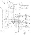
- control arrangement 9 is that part of the control arrangement 9 shown in highly schematic form in a block diagram, which serves the load when the microprocessor fails 7 to be able to sell. All others to understand the Parts not necessary for the invention are omitted.
- the control arrangement 9 contains one Microprocessor 19, the entire function monitoring of the hoist 1 takes over.
- a winding temperature monitoring shown. This includes a temperature sensitive Resistor 21, which is housed in the motor 8 and of the connection lines 22 to inputs 23 of the microprocessor connected.
- the microprocessor controls 19 the movements of the cable drum 3.
- the microprocessor 19 has three inputs 24, 25 and 26 on.
- At the input 24 is the push button 14 with his Working contact, the other connection with one of which is not Power supply shown further via a line 27 connected is.
- the push button 15 for controlling the lowering movement lies with its working contact between the connecting line 27 and the entrance 25
- Push button switch 28 is present, the normally open contact actuates is as soon as one of the two push buttons 14 and 15 the pressure point is pushed in. This is supposed to Motor 8 started at the higher speed will.
- This additional, effective behind the pressure point Key switch 28 is at one end with its working contact the connecting line 27 and at the other end to the entrance 26 connected.
- the key switch 28 is, so to speak behind the pressure point, as is the case with pendant switches control of hoists is common.
- the microprocessor 19 also has four outputs 32, 33, 34 and 35. These outputs 32, 33, 34 and 35 are connected to relays whose magnetic windings 36, 37, 38 and 39 are shown, each of which has an associated one Make contact 41 ... 44 actuated.
- the other power connector for the magnetic windings 36 ... 39 is the Not drawn for clarity.
- Each of the normally open contacts 41 ... 44 is in the control circuit of a total of four motor or control contactors 45, 46, 47 and 48, whose control windings together at one end connected to a power supply line 49 are.
- the other end of the motor contactor control windings 45 ... 48 is via the corresponding working contact 41 ... 44 with the other connection 51 of the power supply connected.
- Motor contactors 45 ... 48 include a number of Working contacts 52, only three of which are shown are to the motor 8 with phase conductors L1, L2 and L3 one Three-phase network to connect.
- an auxiliary switching control device 54 is actuated.
- a control relay 55 whose magnetic winding 56 is connected to the output 53 is.
- Relay 55 also includes a normally closed contact 57, the one end at the input 25 of the microprocessor 19 and at the other end with the control circuit of the motor contactor 47 connected is.
- the work contact 57 is about a Line 58 to the connection point between the control winding 47 and the make contact 43 connected.
- control circuit arrangement 9 shown so far works as follows:
- the Initialization program can, for example, test routines included, in which it is checked whether the individual Control and sensor work properly. Once this Check routine has expired and no error is found could be, the microprocessor 19 changes to that normal control program in which the movement of the Cable drum 3 is controlled via the pendant button 13.
- the microprocessor outputs 19 a voltage signal from its output 53, which causes the magnetic winding 56 to make the normally closed contact 57 opens.
- the microprocessor 19 recognizes or through which the microprocessor 19 becomes inoperable, the microprocessor 19 gives this Signal off, i.e. from now on it remains the same Working contact 57 opened. This is the galvanic Connection between the push button switch 15 and the Circuit of the control winding 57 interrupted.
- the microprocessor 19 thereby receives its input 25 from the supply line 27 voltage, which is interpreted as a signal for lifting the load 7. Since the actuation of the push button 14 only up to the pressure point the working contact of the push button remains 28 open. This corresponds to the "slow” function Lift ". To perform this function, the microprocessor generates 19 at its output 32 a voltage signal gets into the magnetic winding 36, which then makes the normally open contact 41 closes, causing the control winding of the Contactor 45 receives power from lines 51 and 49 and the appropriate contacts closes so that the motor 8 with the low speed in terms of lifting the load 7 in Turns.
- the push button 14 is actuated beyond the pressure point, thereby additionally the working contact of the key switch 28 is also closed.
- the voltage signal at the output 32 switched off and instead a voltage signal on the Output 33 switched on.
- the magnetic winding 37 receives Current and closes the make contact 42.
- the Control winding for contactor 45 now receives the control winding for the contactor 46 current from the associated Supply voltage and the motor 8 is connected to the network turned on that he with the appropriate direction of rotation and the high speed works.
- Push button 15 actuated. This corresponds to the depression the push button 15 to the pressure point of lowering with the low speed and pressing over the pressure point, i.e. the additional actuation of the Key switch 28, lowering at high speed.
- the control winding of the contactor 47 current For lowering at low speed receives, controlled by the microprocessor 19 and the Magnet winding 38, the control winding of the contactor 47 current, while lowering at high speed the Control winding of the contactor 48 is supplied with current.
- auxiliary control switching device 54 can be provided, the input 24 with the hot end of the control winding of the motor contactor 45 connects.
- auxiliary control switching device shown in Fig. 2 54 can also be used in a similar form in hoists 1 be in which the drive motor 8 is not directly from the Mains is fed, but via a frequency converter.
- the wiring of the microprocessor 19 to his Inputs 24, 25 and 25 is as described above.
- the frequency converter is in a known manner single or multi-phase power supply connected. This Connection is omitted for the sake of clarity.
- the supply voltage for the motor 8 is over three Outputs 64, 65 and 66 issued. These outputs are via working contacts 67, 68 and 69 on the windings of the Motors 8.
- the working contacts 67 ... 69 are the contacts a motor contactor 71, the control winding of which is shown.
- the motor contactor 71 lies with its control winding on the Control output 53, at which the auxiliary control switching device 54 is connected.
- the Microprocessor 19 After switching on, the Microprocessor 19 initializes and generates the at the end Initialization phase a voltage signal at its output 53. With this voltage signal 53 the relay 55 and the contactor 71 actuated. The operation of the relay 55 leads to the opening of the normally closed contact 57, with which the galvanic Connection between the push button 15 and the Contactor 75 is interrupted. At the same time this will make contacts 67 ... 69 closed, with which motor 8 is connected to the frequency converter 63. By pressing the push buttons 14 and 15, if necessary by additional actuation of the key switch 28, the Frequency of the frequency converter 63 stepless from zero to can be adjusted to the maximum frequency.
- a control arrangement for the motor of a hoist is based on a microprocessor.
- This microprocessor controls the power elements that power supply to affect the motor of the hoist. So with one Failure of the microprocessor at least lowered the load an auxiliary control switching device is available.
- This auxiliary control switching device is by the functional microprocessor deactivated and is at inactive microprocessor active. In the active state is at least one signal line bypassing the Microprocessor directly with that power element coupled, which is turned on to the engine in mind of lowering.
Landscapes
- Engineering & Computer Science (AREA)
- Mechanical Engineering (AREA)
- Power Engineering (AREA)
- Elevator Control (AREA)
- Control And Safety Of Cranes (AREA)
- Control Of Multiple Motors (AREA)
- Relay Circuits (AREA)
Abstract
Description
Claims (20)
- Steuerungsanordnung (9) für ein einen Elektromotor (8) aufweisendes Hebezeug (1),mit einer Eingabeeinrichtung (13), die dazu eingerichtet ist Signale abzugeben, die wenigstens drei Betriebszuständen wie "Heben", "Senken" und "Stillstand" entsprechen,mit wenigstens einem Motorschütz oder -relais (45.. 48,71,75), über das eine Stromversorgung an den Elektromotor (8) anschließbar ist, um den Elektromotor (8) in Gang zu setzen, undmit einem Mikroprozessor (19), der wenigstens zwei Eingangsanschlüsse (24,25,26), an die die Eingabeeinrichtung (13) angeschlossen ist, sowie wenigstens einen Ausgangsanschluß (32..35), zum Ausgeben von Steuersignalen für den Motorschütz oder das Motorrelais (45..48,71,75), aufweist undmit einer Hilfssteuerschalteinrichtung (54), über die ein Eingangsanschluß (25) mit einem Leistungselement (45,75) zum Steurn des Elektromotors (8) oder einem Ausgang (34) des Mikroprozessors (19) verbindbar ist.
- Steuerungsanordnung nach Anspruch 1, dadurch gekennzeichnet, daß die Eingabeeinrichtung (13) dazu eingerichtet ist Signale abzugeben, die wenigstens zwei weiteren Betriebszuständen wie "schnell Heben" und "schnell Senken" entsprechen.
- Steuerungsanordnung nach Anspruch 1, dadurch gekennzeichnet, daß die Eingabeeinrichtung (13) elektromechanische oder elektronische Schalteinrichtungen (14,15,28) enthält.
- Steuerungsanordnung nach Anspruch 1, dadurch gekennzeichnet, daß jede elektromechanische oder elektronische Schalteinrichtung (14,15,28) einem Betriebszustand mit Ausnahmen des Betriebszustands "Stillstand" zugeordnet ist.
- Steuerungsanordnung nach Anspruch 1, dadurch gekennzeichnet, daß die Eingabeeinrichtung von einem Handsteuerschalter (13) gebildet ist.
- Steuerungsanordnung nach Anspruch 1, dadurch gekennzeichnet, daß für jeden Betriebszustand mit Ausnahmen des Betriebszustands "Stillstand" ein eigener Motorschütz oder ein eigenes Motorrelais (45..48) vorgesehen ist.
- Steuerungsanordnung nach Anspruch 1, dadurch gekennzeichnet, daß der Elektromotor (8) in allen Betriebszuständen mit Ausnahme des Betriebszustands "Stillstand" über einen Frequenzumrichter (63) mit Strom versorgt wird.
- Steuerungsanordnung nach Anspruch 1, dadurch gekennzeichnet, daß der Mikroprozessor (19) für die Betriebszustände "Heben", "Senken" und "schnell" je einen Eingangsanschluß (24,25,26) aufweist.
- Steuerungsanordnung nach Anspruch 1, dadurch gekennzeichnet, daß die Hilfssteuerschalteinrichtung (54) Mittel bildet, die beim Ausfall des Mikroprozessors (19) und/oder des Frequenzumrichters (63) einen Notbetrieb zumindest zum Absenken ermöglichen.
- Steuerungsanordnung nach Anspruch 1, dadurch gekennzeichnet, daß die Hilfssteuerschalteinrichtung (54) zur manuellen Betätigung eingerichtet ist und eine manuelle Betätigungseinrichtung (13) aufweist.
- Steuerungsanordnung nach Anspruch 1, dadurch gekennzeichnet, daß die Hilfssteuerschalteinrichtung (54) zur automatischen Betätigung eingerichtet ist und einen Steuereingang aufweist.
- Steuerungsanordnung nach Anspruch 11, dadurch gekennzeichnet, daß der Mikroprozessor (19) einen Hilfsteuerausgang (53) aufweist, der mit dem Steuereingang der Hilfssteuerschalteinrichtung (54) verbunden ist.
- Steuerungsanordnung nach Anspruch 1, dadurch gekennzeichnet, daß Hilfssteuerschalteinrichtung (54) wie ein Ruhekontakt eines elektromechanischen Relais wirkt.
- Steuerungsanordnung nach Anspruch 1, dadurch gekennzeichnet, daß der Mikroprozessor (19) ein Programm enthält, das derart gestaltet ist, daß nach dem Einschalten der Versorgungsspannung für den Mikroprozessor (19) eine Prüfroutine durchlaufen wird und erst nach erfolgreichem Abschluß der Prüfroutine die Hilfsteuerschalteinrichtung (54) in einen Zustand gebracht wird, in der die Verbindung zwischen dem betreffenden Eingang des Mikroprozessors (19) mit dem betreffenden Ausgang des Mikroprozessors (19) oder dem betreffenden Leistungselement (47,75) unterbrochen ist.
- Steuerungsanordnung nach Anspruch 1, dadurch gekennzeichnet, daß die Hilfssteuerschalteinrichtung (54) mit demjenigen Eingangsanschluß (25) des Mikroprozessors (19) verbunden ist, der dem Betriebszustand "Senken" entspricht.
- Steuerungsanordnung nach Anspruch 1, dadurch gekennzeichnet, daß die Hilfssteuerschalteinrichtung (54) mit demjenigen Ausgangsanschluß (34) des Mikroprozessors (19) oder demjenigen Leistungselement (47,75) verbunden ist, der dem Betriebszustand "Senken" entspricht.
- Steuerungsanordnung nach Anspruch 1, dadurch gekennzeichnet, daß die Hilfssteuerschalteinrichtung (54) zusätzlich mit wenigstens einem weiteren Schütz (71,75) oder Relais verbunden ist, der bzw. das derart beschaltet ist, daß in einem schaltzustand der Frequenzumrichter (63) überbrückt ist.
- Steuerungsanordnung nach Anspruch 1, dadurch gekennzeichnet, daß die Hilfssteuerschalteinrichtung (54) eine elektromechanische Schalteinrichtung ist.
- Steuerungsanordnung nach Anspruch 1, dadurch gekennzeichnet, daß Hilfssteuerschalteinrichtung (54) wenigstens einen Ruhekontakt aufweist.
- Steuerungsanordnung nach Anspruch 1, dadurch gekennzeichnet, daß eine Zeituhr vorhanden, die die Betriebszeit im Notbetrieb erfaßt.
Applications Claiming Priority (2)
| Application Number | Priority Date | Filing Date | Title |
|---|---|---|---|
| DE19643408A DE19643408C2 (de) | 1996-10-21 | 1996-10-21 | Notbetriebssteuerung für ein Hebezeug |
| DE19643408 | 1996-10-21 |
Publications (2)
| Publication Number | Publication Date |
|---|---|
| EP0837552A2 true EP0837552A2 (de) | 1998-04-22 |
| EP0837552A3 EP0837552A3 (de) | 1998-12-02 |
Family
ID=7809345
Family Applications (1)
| Application Number | Title | Priority Date | Filing Date |
|---|---|---|---|
| EP97117520A Withdrawn EP0837552A3 (de) | 1996-10-21 | 1997-10-09 | Notbetriebssteuerung für ein Hebezeug |
Country Status (2)
| Country | Link |
|---|---|
| EP (1) | EP0837552A3 (de) |
| DE (1) | DE19643408C2 (de) |
Families Citing this family (3)
| Publication number | Priority date | Publication date | Assignee | Title |
|---|---|---|---|---|
| DE10148408C1 (de) * | 2001-09-29 | 2002-11-14 | Hoffmann Foerdertechnik Gmbh W | Sicherheitsbremse für einen Elektrokettenzug |
| DE102008053822B3 (de) * | 2008-10-27 | 2010-06-17 | Siemens Aktiengesellschaft | Vorrichtung und Verfahren zur Speisung eines Abnehmernetzes mit der elektrischen Leistung eines Versorgungsnetzes |
| DE102017117604B4 (de) * | 2017-08-03 | 2019-06-19 | Kriwan Industrie-Elektronik Gmbh | Verfahren zum Betreiben wenigstens eines Elektromotors und/oder einer damit gekoppelten, nichtfahrenden Arbeitsmaschine sowie eine nichtfahrende Arbeitsmaschine |
Family Cites Families (5)
| Publication number | Priority date | Publication date | Assignee | Title |
|---|---|---|---|---|
| US4636962A (en) * | 1983-05-24 | 1987-01-13 | Columbus Mckinnon Corporation | Microprocessor-controlled hoist system |
| DE3428215A1 (de) * | 1984-07-31 | 1986-02-13 | Siemens AG, 1000 Berlin und 8000 München | Anordnung zum ueberwachen einer speicherprogrammierbaren steuereinrichtung |
| KR940001098B1 (ko) * | 1988-12-28 | 1994-02-14 | 미쯔비시 덴끼 가부시기가이샤 | 가변속형 전기호이스트 |
| FI922326A0 (fi) * | 1992-02-27 | 1992-05-21 | Electromotive Systems Inc | Bromsmanoeverings-kontrollkretssystem foer anvaendning vid mikroprocessor baserad motorstyrning. |
| US5343134A (en) * | 1993-05-03 | 1994-08-30 | Harnischfeger Corporation | Method for checking brake torque |
-
1996
- 1996-10-21 DE DE19643408A patent/DE19643408C2/de not_active Expired - Lifetime
-
1997
- 1997-10-09 EP EP97117520A patent/EP0837552A3/de not_active Withdrawn
Also Published As
| Publication number | Publication date |
|---|---|
| DE19643408A1 (de) | 1998-04-30 |
| EP0837552A3 (de) | 1998-12-02 |
| DE19643408C2 (de) | 2001-07-26 |
Similar Documents
| Publication | Publication Date | Title |
|---|---|---|
| WO2019086205A1 (de) | Sicherheitsüberwachungsvorrichtung zum überwachen von sicherheitsrelevanten zuständen in einer personenförderanlage sowie verfahren zum betreiben derselben | |
| DE1506484B1 (de) | Notschaltung fuer einen Aufzug | |
| DE68906970T2 (de) | Steuermittel fuer einen elektrischen universalmotor. | |
| EP0837552A2 (de) | Notbetriebssteuerung für ein Hebezeug | |
| EP1898280B1 (de) | Steuerungsvorrichtung mit einem Bus zum Betrieb einer Maschine | |
| DE1920297C3 (de) | Sicherheitsvorrichtung für eine Fahrzeugtür mit Mitteln zum Sperren und Freigeben der Türbetätigung | |
| DE3924940A1 (de) | Drehzahlregelbares elektrisches windwerk | |
| EP1044921A2 (de) | Antrieb mit einer Steuerung für ein Hubwerk eines Hebezeuges, insbesondere ein kleinbauendes Hebezeug | |
| DE2139251A1 (de) | Motor- und Hebewerk-Steueranordnung | |
| DE2501753C3 (de) | Einrichtung zur wahlweisen Fern- und Nahsteuerung für hydraulisch betätigte Kräne | |
| EP0959396B1 (de) | Störungssichere Steuerungsanordnung für ein Hebezeug | |
| DE2449725B2 (de) | Zweihand-Sicherheitsschaltungsanordnung zum Einschalten einer Arbeitsmaschine und zur Auslösung eines hin- und hergehenden Arbeitshubes | |
| DE69920808T2 (de) | Einrichtung zur Endstellungsanzeige eines bidirektionalen mobilen Elements, insbesondere einer Rolladenwickelwelle, und Antriebsvorrichtung eines bidirektionalen mobilen Elements ausgerüstet mit solcher Endstellungseinrichtung | |
| DE2450020A1 (de) | Verfahren zum steuern einer webmaschine mit mehreren webfaechern und anordnung zum durchfuehren des verfahrens | |
| DE1909862A1 (de) | ||
| EP2146549B1 (de) | Sicherheitseinrichtung für ein Gargerät mit Mikrowellenfunktion hoher Leistung | |
| DE10354591B4 (de) | Aufzuganlage | |
| DE3638680C2 (de) | ||
| DE2612246C2 (de) | Hauptstrom-Steuervorrichtung für Kleinhebezeuge | |
| DE957496C (de) | Anfahr- und Bremssteuerung fuer in Leonardschaltung betriebene Gleichstrommotoren | |
| DE2947769A1 (de) | Steuereinrichtung fuer motorantriebe von stufenschaltern | |
| DE609040C (de) | Einrichtung zur Verhuetung des gleichzeitigen Anfahrens mehrerer Foerdermaschinen | |
| DE276175C (de) | ||
| DE29604801U1 (de) | Sicherheitseinrichtung für Hebegeräte mit elektrischer Steuerung | |
| EP1126485A2 (de) | Schnellstoppschaltkreis |
Legal Events
| Date | Code | Title | Description |
|---|---|---|---|
| PUAI | Public reference made under article 153(3) epc to a published international application that has entered the european phase |
Free format text: ORIGINAL CODE: 0009012 |
|
| AK | Designated contracting states |
Kind code of ref document: A2 Designated state(s): BE DE FR GB IT NL |
|
| PUAL | Search report despatched |
Free format text: ORIGINAL CODE: 0009013 |
|
| AK | Designated contracting states |
Kind code of ref document: A3 Designated state(s): AT BE CH DE DK ES FI FR GB GR IE IT LI LU MC NL PT SE |
|
| 17P | Request for examination filed |
Effective date: 19990507 |
|
| AKX | Designation fees paid |
Free format text: BE DE FR GB IT NL |
|
| 17Q | First examination report despatched |
Effective date: 20010905 |
|
| GRAH | Despatch of communication of intention to grant a patent |
Free format text: ORIGINAL CODE: EPIDOS IGRA |
|
| STAA | Information on the status of an ep patent application or granted ep patent |
Free format text: STATUS: THE APPLICATION IS DEEMED TO BE WITHDRAWN |
|
| 18D | Application deemed to be withdrawn |
Effective date: 20030114 |