EP0837581A2 - Im Betriebszustand austauschbare Zwischenverbindungen für Stapel-Netzwerkknotenpunkte - Google Patents
Im Betriebszustand austauschbare Zwischenverbindungen für Stapel-Netzwerkknotenpunkte Download PDFInfo
- Publication number
- EP0837581A2 EP0837581A2 EP19970110068 EP97110068A EP0837581A2 EP 0837581 A2 EP0837581 A2 EP 0837581A2 EP 19970110068 EP19970110068 EP 19970110068 EP 97110068 A EP97110068 A EP 97110068A EP 0837581 A2 EP0837581 A2 EP 0837581A2
- Authority
- EP
- European Patent Office
- Prior art keywords
- hub
- connector
- network
- adjacent
- network hub
- Prior art date
- Legal status (The legal status is an assumption and is not a legal conclusion. Google has not performed a legal analysis and makes no representation as to the accuracy of the status listed.)
- Withdrawn
Links
- 239000004020 conductor Substances 0.000 claims abstract description 16
- 238000000034 method Methods 0.000 claims abstract description 14
- 238000004891 communication Methods 0.000 claims abstract description 7
- 238000003780 insertion Methods 0.000 claims description 24
- 230000037431 insertion Effects 0.000 claims description 24
- 230000008878 coupling Effects 0.000 claims 4
- 238000010168 coupling process Methods 0.000 claims 4
- 238000005859 coupling reaction Methods 0.000 claims 4
- 238000007726 management method Methods 0.000 description 17
- 238000010586 diagram Methods 0.000 description 4
- 238000009434 installation Methods 0.000 description 2
- 230000002093 peripheral effect Effects 0.000 description 2
- 230000002457 bidirectional effect Effects 0.000 description 1
- 230000002950 deficient Effects 0.000 description 1
- 230000003111 delayed effect Effects 0.000 description 1
- 230000007257 malfunction Effects 0.000 description 1
- 230000006855 networking Effects 0.000 description 1
- 230000003287 optical effect Effects 0.000 description 1
- 238000013024 troubleshooting Methods 0.000 description 1
Images


Classifications
-
- H—ELECTRICITY
- H04—ELECTRIC COMMUNICATION TECHNIQUE
- H04L—TRANSMISSION OF DIGITAL INFORMATION, e.g. TELEGRAPHIC COMMUNICATION
- H04L12/00—Data switching networks
- H04L12/28—Data switching networks characterised by path configuration, e.g. LAN [Local Area Networks] or WAN [Wide Area Networks]
- H04L12/44—Star or tree networks
Definitions
- This invention relates to data communications within a computer network. Specifically, this invention relates to a method and apparatus for adding network hubs to and removing network hubs from a network hub stack without interrupting data communications within the stack and between computers connected to the stack.
- a network hub stack serves as a common connection point for networked computer systems and peripherals.
- networked computer systems and peripherals are connected to a network hub having a fixed number of connection ports.
- a network hub it is common for a network hub to have 8, 12, 16, 24, or 48 ports. As the size of a network grows, so must the number of connection ports.
- One common way to provide more connection ports is by connecting a plurality of hubs together into a network hub stack.
- the first type of data is network traffic that consists of the data flowing between computing devices connected to the network, such as desktop PCS, printers, servers, and the like.
- the second type of data is management data that is used by the network hub stack to manage network traffic.
- One method of connecting network hubs together is to use a coaxial cable (often called a ThinLan) to carry the network and management data between hubs.
- a coaxial cable often called a ThinLan
- This technique is known in the art as "in-band” management and requires that the hubs generate packets containing the management data and transmit these packets on the coaxial cable along with the network traffic.
- the coaxial cable is connected to the hub using a "T" connector such that connecting and disconnecting the coaxial cable from the hub does not affect the flow of data to the other hubs. Accordingly, this technique provides the stack "hot-swap" capability because it is possible to connect and disconnect hubs from the stack without affecting the flow of data to other hubs.
- In-band management requires fairly advanced hardware because hubs must communicate with each other in the same manner that other computing devices communicate over the network.
- the management data adds to the overloaded condition and may be delayed.
- the network malfunctions for some reason such as a defective network card flooding the network with useless packets
- management traffic cannot be transmitted.
- Another method of connecting hubs together is to use a coaxial cable to carry the network data between hubs as described above, and some other type of cable to carry the management data between hubs.
- This technique is known in the art as out-of-band management.
- a twisted-pair cable comprising twisted-pair wires with phone-type (RJ-45) connectors is used to carry the management data.
- Each hub has an "in” port and an “out” port, and the stack is formed be chaining hubs together such that the out port of one hub is connected to the in port of the next hub in the stack.
- Many of the signals that are carried by the twisted-pair cable are nonglobal and are not passed to all hubs in the stack. These signals transmit messages between specific hubs.
- Out-of-band management using separate cables has several advantages. First, the hub does not actually have to communicate packets to and from the coaxial cable, so the hub hardware can be simpler. Second, management traffic does not use any of the bandwidth of the coaxial cable. Finally, management data can be transmitted even if the network is overloaded or dead.
- out-of-band management is that it is not completely hot-swappable. While the flow of network traffic between hubs is not interrupted, as soon as one twisted-pair cable is removed, management data cannot be transmitted to all hubs in the stack.
- backplane or alternatively, "fat" cable to connect network hubs.
- These cables typically have between 50 and 70 conductors.
- a first set of conductors carry global signals, such as power, ground, and network traffic.
- a second set of conductors carry nonglobal signals that transmit messages between specific hubs.
- backplane cables are connected to in and out ports on each hub to form a chain of hubs.
- each conductor of the first set is connected directly from a pin on the in port to a pin on the out port, and to the hub circuitry, thereby forming a "T" connection.
- Each nonglobal pin is connected directly to the hub circuitry, without a direct connection between the in and the out ports.
- backplane cables are that there is only one cable needed to form a connection between two adjacent hubs, yet the cables support out-of-band management. This simplifies installation, minimizes cost, and provides a simpler, easier to maintain stack. Also, backplane cables can provide multiple network paths, compared to the single path provided by a coaxial cable. Finally, backplane cables can be used to distribute power signals, thereby eliminating the need to have a power supply in each hub.
- backplane cables render the network hub stack completely non-hot-swappable. As soon as one cable is removed, both management data and network traffic cannot flow to all hubs in the stack. In addition, if power is being distributed throughout the stack, then some hubs will lose power.
- the present invention is method and apparatus for connecting network hubs to and disconnecting network hubs from a network hub stack without significancy interrupting the flow of data within the network hub stack.
- the invention provides a "T" connection for global signals that are distributed to all hubs in the stack, and a switched connection for nonglobal signals that are only distributed between adjacent hubs or specific hubs.
- the invention includes an insert indication that causes corresponding nonglobal signals from adjacent hubs to be connected together via the switched connection when not connected to a hub, and causes corresponding nonglobal signals to be routed to the in and out ports of the hub when connected to the hub.
- a "hot-swap" module has four cables with each cable having a connector, with first and second cables that are each connectable to adjacent hubs and third and fourth cables that are each connectable a middle hub.
- the switched connections route the nonglobal signals to the middle hub when the third and fourth cables are connected to the middle hub, and route the nonglobal signals between the first and second cables when the third and fourth cables are not connected to the middle hub.
- a hot-swap module has connectors mounted to a housing and cables that are connectable to adjacent hubs.
- the connectors coupled to the housing attach to corresponding connectors on a hub.
- a hot-swap module is used to couple prior art backplane cables to hubs.
- the hot-swap module includes cable in and out connectors that are connectable to prior art backplane cables, and hub in and out connectors that are connectable to corresponding connectors on a network hub.
- the switched connection routes the nonglobal signals to the hub in and out connectors when the module is connected to the hub, and routes the nonglobal signals between the cable in and out connectors when the module is not connected to the hub. Data communication within the hub is ensured as long as the backplane cables are connected to the hot-swap module.
- the insert indication is simply a user activated switch that indicates to the switched connection whether connection has been made to a hub.
- communication within the stack is not interrupted if the user sets the switch to a "disconnected" setting before disconnecting from a hub, and sets the switch to a "connected” setting after connecting to a hub.
- at least one sensor generates the insertion indication. The sensor is adapted to generate the insertion indication based on whether the backplane cables are coupled to the hub.
- the insert indication is generated based on whether a circuit is completed between the hot-swap module and a hub.
- Figure 1 is a diagram of a prior art computer network.
- Figure 2 is a schematic diagram showing the hot-swap circuit of the present invention.
- FIG. 3 shows an embodiment of the present invention.
- Figure 4 shows an embodiment of the insert indication of Figure 2.
- FIG. 5 shows another embodiment of the present invention.
- Figure 6 shows yet another embodiment of the present invention.
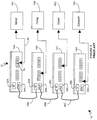
- FIG. 1 is a diagram of a prior art computer network 10.
- Prior art computer network 10 includes network hub stack 12, which includes network hubs 14A, 14B, 14C, and 14D, and a variety of networked computing devices, such as server 16A, plotter 16B, laser printer 16C, and desktop computer 16D.
- Each computing device is coupled to a network port via a network cable.
- server 16A is coupled to port 18 via network cable 20.
- Each network hub has a backplane "in” port and a backplane “out” port to allow that hub to be connected to another hub in the stack. Accordingly, hubs 14A, 14B, 14C, and 14D have backplane in ports 22A, 22B, 22C, and 22D, and backplane out ports 24A, 24B, 24C, and 24D, respectively.
- Each network hub in stack 12 is connected to at least one other network hub by a backplane cable. These cables are also known in the art as "fat" cables. Accordingly, port 24A of hub 14A is connected to port 22B of hub 14B via backplane cable 26A, port 24B of hub 14B is connected to port 22C of hub 14C via backplane cable 26B, and port 24C of hub 14C is connected to port 22D of hub 14D via backplane cable 26C. Since hub 14A is at the top of the stack, in port 22A of hub 14A is not used. Likewise, out port 24D of hub 14D is not used.
- a hub could be disconnected from the stack without interrupting data flow throughout the network.
- newer network hub stacks such as stack 12
- backplane cables have a first set of conductors that are bidirectional and global.
- each conductor of the first set is connected directly from a pin on the in port to a pin on the out port, and to the hub circuitry, thereby forming a "T" connection.
- Conductors of the first set are used to carry signals such as power, ground, clock signals, and the like
- Backplane cables also have a second set of conductors that are nonglobal. Each nonglobal pin is connected directly to the hub circuitry, without a direct connection between the in and the out ports. Conductors of the second set are used to carry messages between specific hubs in a network hub stack.
- FIG. 2 is a schematic diagram showing the hot-swap circuit 28 of the present invention.
- Circuit 28 includes cable in port 32A, cable out port 32B, hub in port 34A, hub out port 34B, insert indication 36, switches 38A, 38B, and 38n, and switches 40A, 40B, and 40n.
- Cable in port 32A is coupled to cable 30A, which in turn is connectable to the out port of another hub in the network hub stack.
- cable out port 32B is coupled to cable 30B, which is connectable to the in port of another hub in the network hub stack.
- cables 30A and 30B are hard-wired to circuit 28.
- cables 30A and 30B are prior art backplane cables, and ports 32A and 32B are connectors similar to those found on a network hub. Both embodiments will be discussed in greater detail below.
- Ports 34A and 34B are connected to the in and out ports, respectively, of a network hub. The hub connected to ports 34A and 35B is hot-swappable due to circuit 28.
- Bus 42 carries global signals G(1:m) between ports 32A, 32B, 34A, and 34B.
- Global signals G(1:m) include power and ground signals, clock signals, certain types of network traffic, and other signals that can be supplied to all hubs.
- the portion of bus 42 that connects ports 32A and 32B is required because it provides signals G(1:m) to the hubs connected to cables 30A and 30B when no hub is connected to ports 34A and 34B. In contrast, there is potential redundancy in the portion of bus 42 that is connected to ports 34A and 34B.
- prior network hubs provided connectivity for global signals by connecting such signals between corresponding pins of the in and out ports of the hub.
- bus 42 when connected to such a hub, bus 42 need only provide global signals G(1:m) to either port 34A or port 34B, thereby lowing assembly costs.
- circuit 28 since circuit 28 must connect global signals G(1:m) between ports 32A and 32B, a hub designed to work exclusively with the present invention need not provide connectivity for global signals between the in and out ports of the hub. Accordingly, it may be necessary to provide global signals G(1:m) to both ports 34A and 34B if it is not known which port is used within the hub to provide the global signals.
- the global signals need only be provided to one port.
- nonglobal, switched signals NGIN(1:n) and NGOUT(1:n) are signals that cannot be provided globally to all hubs in a stack. Such signals are used to pass messages between specific hubs in a stack.
- a backplane cable such as cable 30A has 68 conductors, with about seven conductors dedicated to nonglobal switched connections, about 34 conductors dedicated to power and ground signals, and the rest of the conductors either carrying other global signals or having no connections. Accordingly, in such a typical configuration m (the number of global signals) will be approximately 61 and n (the number of nonglobal switched signals) will be approximately seven.
- Insert indication 36 generates a signal indicating whether circuit 28 is connected to a network hub via ports 34A and 34B.
- the signal can assume two states, “connected” and “disconnected”, and is supplied to switches 38A, 38B, 38n, 40A, 40B, and 40n via connections 44.
- switches 38A, 38B, and 38n connect signals NGIN(0:n) between cable in port 32A and hub in port 34A
- switches 40A, 40B, and 40n connect signals NGOUT(0:n) between cable out port 32B and hub out port 34B.
- switches 38A, 38B, and 38n, and switches 40A, 40B, and 40n correspondingly connect the signals NGIN(0:n) and NGOUT(0:n) together via connections 46, effectively connecting cables 30A and 30B together and bypassing the hub.
- Switches 38A, 38B, 38n, 40A, 40B, and 40n can be implemented using any suitable mechanical or electronic switch that is known in the art.
- the switches may be manual mechanical switches, in which case insert indication 36 is a mechanical signal (such as a user pushing a button) that moves the switches to route the signals as described above.
- the switches may be implemented by mechanical relays or electronic muxes, in which case insert notification is an electronic signal. Mechanical relays and electronic muxes can also receive power via global signals G(1:m), which will typically include power and ground.
- FIG. 3 shows an embodiment 48 of the present invention.
- circuit 28 of Figure 2 is contained within module 50.
- Cables 30A and 30B correspond to the similarly referenced cables in Figure 2, and are attached to connectors 52A and 52B, respectively.
- Port 34A of Figure 2 is implemented by cable 54A and connector 56A
- Port 34B is implemented by cable 54B and connector 56B.
- the hub connected to connectors 56A and 56B is hot-swappable.
- Each connector 52A and 52B is coupled to an adjacent hub in the stack. If one of these connectors is connected directly to a hub, then that hub is not hot-swappable.
- a gender changing adapter can be connected to connector 52B to couple connector 52B to the connector 52A of another module 48. In this manner, a series of modules can be chained together.
- Insert indication 36 of Figure 2 is implemented by switch 58.
- switch 58 can provide a mechanical signal if mechanical switches are used or can provide an electrical signal if relays or muxes are used.
- a user would slide switch 58 to the connected position after connecting connectors 56A and 56B to a hub, and slide switch 58 to the disconnected position before disconnecting connectors 56A and 56B from a hub.
- the embodiment shown in Figure 3 is also useful when troubleshooting a problem in the network hub stack.
- the nonglobal switched signals of each hub can be selectively by passed from that hub by toggling the switch 58 associated with each hub, without having to physically disconnect the cables from the hub.
- At least one of the connectors 56A and 56B are provided with an insertion detector, which may be a contact switch, an optical switch, or other types of detectors or sensors as are known in the art. If both connectors are provided with an insertion detector, the signals provided by the insertion detectors must be gated such that the "connected" signal is generated only when both connectors are inserted, and the "disconnected” signal is generated when either connector is removed.
- each insertion detector is arranged to indicate that the connector is disconnected before electrical contact is terminated between the hub and the respective connector, thereby ensuring that there is not a time period wherein a connector has been disconnected from a hub and circuit 28 has not yet switched to bypass the hub.
- a single insertion detector may be used in one of the connectors. However, such a configuration would require that the connector with the detector be removed first and inserted last.
- a loop between a pin on the in port of the hub and the out port of the hub is used to generate the insertion indication signal.
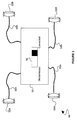
- FIG 4 shows another embodiment of insert indication 36 of Figure 2.
- hot-swap module 62 having circuit 28 of Figure 2 is coupled to hub 60.
- ground signal 68 is provided to a pin on port 34A of module 60, which in turn is coupled to a corresponding pin on port 64A of hub 60.
- the pin on port 64A is coupled to a corresponding pin on port 64B of hub 60 via wire 66.
- the circuit is completed to a corresponding pin on port 34B of module 62, which in turn is coupled to five volt power source 70 via resistance R.
- Insert indication 36 is provided at the circuit node of resistance R and the pin of port 34B.
- the pins in the connectors that carry the ground loop signal can be shorted to ensure that indication 36 is not pulled low until all other pins have made contact.
- Figure 5 shows another embodiment 72 of the hot-swap module. This embodiment is similar to the embodiment shown in Figure 3, however in this embodiment, connectors 74A and 74B (which implement ports 34A and 34B of Figure 2) are mounted to a housing 76. Screws 78 fasten housing 76 to a network hub, providing that hub with the ability to be added or removed from the stack without interrupting data flow within the stack. Similar to embodiment 48 in Figure 3, cables 30A and 30B are connected to housing 76.
- Button 80 implements insert indication 36 and protrudes from housing 76. Inside housing 80 is a switch responsive to the position of button 80. The switch generates the insert indication when button 80 is pressed against the housing of the hub to which housing 76 is attached.
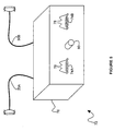
- FIG 6 shows yet another embodiment 82 of the hot-swap module.
- This embodiment provides hot-swap capability to a hub (such as hub 84 in Figure 6) while allowing use of prior art backplane cables (such as cable 86 in Figure 6).
- housing 88 The cables from adjacent hubs are connected to the in and out connectors mounted on housing 88. These cables must remain coupled to housing 88 to ensure that data flow throughout the stack is uninterrupted. Housing 88 is in turn fastened to hub 84 via screws 90, which screw into threaded studs 92.
- the hub side of housing 88 is similar to the hub side shown in Figure 5, with connectors coupled to housing 88 that mate with connectors 94 of hub 84.
- the hub side of housing 88 includes attached cables that are connected to the hub (similar to the hub side of embodiment 48 of Figure 3). While the mounted connectors shown in Figure 5 allow for easy installation and a single insertion detector, separate cables allow the present invention to by used with a variety of hubs wherein the spacing between the in and out ports may vary from hub to hub.
Landscapes
- Engineering & Computer Science (AREA)
- Computer Networks & Wireless Communication (AREA)
- Signal Processing (AREA)
- Small-Scale Networks (AREA)
- Data Exchanges In Wide-Area Networks (AREA)
Applications Claiming Priority (2)
| Application Number | Priority Date | Filing Date | Title |
|---|---|---|---|
| US732652 | 1991-07-19 | ||
| US73265296A | 1996-10-15 | 1996-10-15 |
Publications (1)
| Publication Number | Publication Date |
|---|---|
| EP0837581A2 true EP0837581A2 (de) | 1998-04-22 |
Family
ID=24944440
Family Applications (1)
| Application Number | Title | Priority Date | Filing Date |
|---|---|---|---|
| EP19970110068 Withdrawn EP0837581A2 (de) | 1996-10-15 | 1997-06-19 | Im Betriebszustand austauschbare Zwischenverbindungen für Stapel-Netzwerkknotenpunkte |
Country Status (2)
| Country | Link |
|---|---|
| EP (1) | EP0837581A2 (de) |
| JP (1) | JPH10136007A (de) |
Cited By (5)
| Publication number | Priority date | Publication date | Assignee | Title |
|---|---|---|---|---|
| US8479271B1 (en) | 2011-12-20 | 2013-07-02 | International Business Machines Corporation | Hosting edge applications at the edge of a mobile data network |
| US8693309B2 (en) | 2011-11-16 | 2014-04-08 | International Business Machines Corporation | Fail to wire removable module for network communication link |
| US8724455B2 (en) | 2012-01-20 | 2014-05-13 | International Business Machines Corporation | Distributed control of a fail-to-wire switch for a network communication link |
| US8837318B2 (en) | 2011-09-15 | 2014-09-16 | International Business Machines Corporation | Mobile network services in a mobile data network |
| CN113890779A (zh) * | 2021-11-25 | 2022-01-04 | 浙江国利信安科技有限公司 | 用于通信设备的接入设备和通信系统 |
-
1997
- 1997-06-19 EP EP19970110068 patent/EP0837581A2/de not_active Withdrawn
- 1997-10-09 JP JP9276754A patent/JPH10136007A/ja active Pending
Cited By (10)
| Publication number | Priority date | Publication date | Assignee | Title |
|---|---|---|---|---|
| US8837318B2 (en) | 2011-09-15 | 2014-09-16 | International Business Machines Corporation | Mobile network services in a mobile data network |
| US9014023B2 (en) | 2011-09-15 | 2015-04-21 | International Business Machines Corporation | Mobile network services in a mobile data network |
| US8693309B2 (en) | 2011-11-16 | 2014-04-08 | International Business Machines Corporation | Fail to wire removable module for network communication link |
| US8717872B2 (en) | 2011-11-16 | 2014-05-06 | International Business Machines Corporation | Fail to wire removable module for network communication link |
| US8479271B1 (en) | 2011-12-20 | 2013-07-02 | International Business Machines Corporation | Hosting edge applications at the edge of a mobile data network |
| US8989067B2 (en) | 2011-12-20 | 2015-03-24 | International Business Machines Corporation | Hosting edge applications at the edge of a mobile data network |
| US9072042B2 (en) | 2011-12-20 | 2015-06-30 | International Business Machines Corporation | Hosting edge applications at the edge of a mobile data network |
| US9078203B2 (en) | 2011-12-20 | 2015-07-07 | International Business Machines Corporation | Hosting edge applications at the edge of a mobile data network |
| US8724455B2 (en) | 2012-01-20 | 2014-05-13 | International Business Machines Corporation | Distributed control of a fail-to-wire switch for a network communication link |
| CN113890779A (zh) * | 2021-11-25 | 2022-01-04 | 浙江国利信安科技有限公司 | 用于通信设备的接入设备和通信系统 |
Also Published As
| Publication number | Publication date |
|---|---|
| JPH10136007A (ja) | 1998-05-22 |
Similar Documents
| Publication | Publication Date | Title |
|---|---|---|
| US20030112582A1 (en) | Redundant data and power infrastructure for modular server components in a rack | |
| US5740378A (en) | Hot swap bus architecture | |
| US7590763B2 (en) | Device for use in a system for processing keyboard, video and mouse signals | |
| US7486630B1 (en) | Module for distributed network repeater | |
| EP1008943B1 (de) | Kaskadierter Anschluss von kommuniziernden Geräten | |
| US6462435B1 (en) | Cable detect and EMI reduction apparatus and method | |
| US7766692B2 (en) | Cable interconnect systems with cable connectors implementing storage devices | |
| US6816486B1 (en) | Cross-midplane switch topology | |
| US7644215B2 (en) | Methods and systems for providing management in a telecommunications equipment shelf assembly using a shared serial bus | |
| US5495584A (en) | SCSI bus concatenator/splitter | |
| US5531611A (en) | Connector module for local area network | |
| US5535036A (en) | Input/output module providing mixed optical and electrical signal connectivity in data communications equipment | |
| US20020023184A1 (en) | Fibre channel architecture | |
| CA2337659A1 (en) | Backplane configuration without common switch fabric | |
| US20030191883A1 (en) | Interface for upgrading serial backplane application from ethernet to gigabit ethernet | |
| WO2007016253A1 (en) | Method device including a bypass switch for an ethernet device, method for creating a bypass path and corresponding ethernet network | |
| WO1998028883B1 (en) | Network including multi-protocol cross-connect switch | |
| GB2402771A (en) | Rigid connector for rack mounted servers | |
| EP0947076A1 (de) | Mehrprotokollverzweigerschalter-enthaltendes netzwerk | |
| JP4344108B2 (ja) | 多重の異なる伝送プロトコルの信号をスイッチングするための方法および装置 | |
| US6493319B1 (en) | Test access system and method for digital communication networks | |
| US20080155157A1 (en) | Hot-swappable multi-configuration modular network service system | |
| EP0837581A2 (de) | Im Betriebszustand austauschbare Zwischenverbindungen für Stapel-Netzwerkknotenpunkte | |
| GB2402772A (en) | Server connector with integral network management processor | |
| US20070230148A1 (en) | System and method for interconnecting node boards and switch boards in a computer system chassis |
Legal Events
| Date | Code | Title | Description |
|---|---|---|---|
| PUAI | Public reference made under article 153(3) epc to a published international application that has entered the european phase |
Free format text: ORIGINAL CODE: 0009012 |
|
| AK | Designated contracting states |
Kind code of ref document: A2 Designated state(s): AT BE CH DE DK ES FI FR GB GR IE IT LI LU MC NL PT SE |
|
| STAA | Information on the status of an ep patent application or granted ep patent |
Free format text: STATUS: THE APPLICATION HAS BEEN WITHDRAWN |
|
| 18W | Application withdrawn |
Withdrawal date: 19990608 |