EP0837608A2 - Méthode de codage de données audio et vidéo, et dispositif de codage - Google Patents
Méthode de codage de données audio et vidéo, et dispositif de codage Download PDFInfo
- Publication number
- EP0837608A2 EP0837608A2 EP97117838A EP97117838A EP0837608A2 EP 0837608 A2 EP0837608 A2 EP 0837608A2 EP 97117838 A EP97117838 A EP 97117838A EP 97117838 A EP97117838 A EP 97117838A EP 0837608 A2 EP0837608 A2 EP 0837608A2
- Authority
- EP
- European Patent Office
- Prior art keywords
- coding
- audio
- data
- video
- information
- Prior art date
- Legal status (The legal status is an assumption and is not a legal conclusion. Google has not performed a legal analysis and makes no representation as to the accuracy of the status listed.)
- Granted
Links
Images






















Classifications
-
- H—ELECTRICITY
- H04—ELECTRIC COMMUNICATION TECHNIQUE
- H04N—PICTORIAL COMMUNICATION, e.g. TELEVISION
- H04N19/00—Methods or arrangements for coding, decoding, compressing or decompressing digital video signals
- H04N19/42—Methods or arrangements for coding, decoding, compressing or decompressing digital video signals characterised by implementation details or hardware specially adapted for video compression or decompression, e.g. dedicated software implementation
-
- H—ELECTRICITY
- H04—ELECTRIC COMMUNICATION TECHNIQUE
- H04B—TRANSMISSION
- H04B1/00—Details of transmission systems, not covered by a single one of groups H04B3/00 - H04B13/00; Details of transmission systems not characterised by the medium used for transmission
- H04B1/66—Details of transmission systems, not covered by a single one of groups H04B3/00 - H04B13/00; Details of transmission systems not characterised by the medium used for transmission for reducing bandwidth of signals; for improving efficiency of transmission
- H04B1/665—Details of transmission systems, not covered by a single one of groups H04B3/00 - H04B13/00; Details of transmission systems not characterised by the medium used for transmission for reducing bandwidth of signals; for improving efficiency of transmission using psychoacoustic properties of the ear, e.g. masking effect
-
- H—ELECTRICITY
- H04—ELECTRIC COMMUNICATION TECHNIQUE
- H04N—PICTORIAL COMMUNICATION, e.g. TELEVISION
- H04N19/00—Methods or arrangements for coding, decoding, compressing or decompressing digital video signals
- H04N19/10—Methods or arrangements for coding, decoding, compressing or decompressing digital video signals using adaptive coding
- H04N19/134—Methods or arrangements for coding, decoding, compressing or decompressing digital video signals using adaptive coding characterised by the element, parameter or criterion affecting or controlling the adaptive coding
- H04N19/146—Data rate or code amount at the encoder output
- H04N19/152—Data rate or code amount at the encoder output by measuring the fullness of the transmission buffer
-
- H—ELECTRICITY
- H04—ELECTRIC COMMUNICATION TECHNIQUE
- H04N—PICTORIAL COMMUNICATION, e.g. TELEVISION
- H04N19/00—Methods or arrangements for coding, decoding, compressing or decompressing digital video signals
- H04N19/60—Methods or arrangements for coding, decoding, compressing or decompressing digital video signals using transform coding
- H04N19/61—Methods or arrangements for coding, decoding, compressing or decompressing digital video signals using transform coding in combination with predictive coding
Definitions
- the present invention relates to a video and audio coding method, a coding apparatus, and a coding program recording medium and, more particularly to a coding method, a coding apparatus and a coding program recording medium in which video, audio, or video and audio are captured and coded under software control using a general purpose computer resource.
- the DCT means 5003 is used for performing DCT processing to the input picture data and outputting resulting DCT data.
- the quantization means 5004 is used for quantizing the DCT data and outputting quantized data.
- the variable length coding means 5005 is used for performing variable length coding processing to quantized data to produce variable length coded data that is compressively coded.
- the variable length coded data is input to the bit stream generating means 5006, from which coded data of the video coding apparatus is output as a bit stream which can be transmitted and recorded.
- the inverse-quantization means 5007 is used for performing inverse-quantization processing to the quantized data that is output from the quantization means 5004 and outputting inverse-quantized data.
- the inverse-DCT means 5008 is used for performing inverse-DCT processing to inversely-quantized data and outputting resulting inverse DCT data, which is input to the prediction picture generating means 5009 and output as prediction picture data.
- difference data between the prediction picture data and the input picture data is input, thereby inter-frame coding is performed in the coding section 5001.
- the coding parameter decision means 5002 holds this set parameters and outputs the same to the coding section 5001 for coding.
- a method of deciding a coding type on the basis of information of input video such as "scene change” is disclosed in "picture coding apparatus (Japanese Patent Application Hei. No. 8-98185)".
- variable length coding is performed by allocating a code with the fewest bits to data having the highest frequency in allocation of bits for coding, thereby amount of data is reduced.
- the bit stream generating means 5006 generates a bit stream from the variable-length coded data that is output from the variable length coding means 5005 and outputs the bit stream as an output of the video coding apparatus.
- the inverse-quantization means 5007 inversely quantizes the quantized data that is output from the quantization means 5004 and outputs resulting inversely-quantized data.
- the inverse-DCT processing means 5008 performs two-dimensional inverse DCT processing to the inversely-quantized data for each (8 x 8 pixels) block that is divided by the DCT processing means 5003 and outputs resulting inverse DCT data.
- the prediction picture generating means 5009 generates prediction picture on the basis of the inverse DCT data, to be output. The difference data between the input picture data and the prediction picture is input to the DCT processing means 5003.
- Figure 60 is a flowchart of the prior art audio coding method.
- Figure 61 is a diagram for explaining sampling.
- Figures 62 and 63 are diagrams for explaining subsampling.
- layers 1 to 3 are defined.
- playback quality of sound and required hardware performance becomes higher, and hardware scale becomes larger in the order of 1 ⁇ 2 ⁇ 3.
- steps 1 to 5 are repeated. Audio is continuously input and real-time processing is performed to the same, thereby coded data is output and recorded. On completion of audio input, the coding is completed.
- Coded data stored in the storage device is preserved as MPEG regenerative data.
- the coded data may be transmitted over a network and used.
- the psychoacoustic analysis unit 2661 compares each subband signals with the minimum audible limit indicating inaudible limit level shown in Figure 66.
- Figure 66 shows division of 32 subbands. If the number is increased (256), a graph of the minimum audible limit remains unchanged and subdivision is performed with respect to lateral axis (subband) in the same range shown in Figure 66.
- steps 1 to 7 are repeated, thereby audio coding is performed upon input of audio.
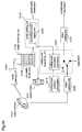
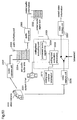
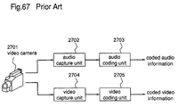
- FIG 67 schematically shows a prior art video and audio coding apparatus.
- the prior art video and audio coding apparatus comprises a video camera 2701, an audio capture unit 2702, an audio coding unit 2703, a video capture unit 2704, and a video coding unit 2705.
- the audio coding unit 2703 performs coding to pro-audio information and outputs coded audio information.
- the video coding unit 2705 performs coding to the pro-video information and outputs coded video information.
- coded data of high playback quality of picture is obtained by performing bit allocation according to human hearing characteristics.
- the audio coding unit and the video coding unit operate independently an use specified hardware with which coding is performed with reliability, thereby coding of video and audio is implemented. It is extremely difficult to realize coding of audio and video as a software program which operates on a multi task operating system using a general-use CPU without using a specified hardware.
- the audio coding method of the seventh aspect further executing the steps of: temporarily storing the sampled audio data in an input buffer; and checking the amount of data within the input buffer to make a comparison between the amount of data and a predetermined value, and based on the result of the comparison, changing the value of the conversion constant n stored in the register; wherein, in the input audio sampling step, the sampled audio data is written into the input buffer, and in the audio data conversion step, sampled audio data is read from the input buffer and subjected to the above-described conversion processing.
- the method of coding audio of the 19th aspect wherein the subband reducing step includes selecting subband signal data skipping r pieces of subband signal data (r: subband selecting constant) among output M pieces of subband signal data obtained in the subsampling step.
- a method for coding video and audio information wherein: performed are the steps of, when analog video information is input and video resolution information is output, converting said analog video information to pro-video information composed of plural discrete digital pixel signals and comprising plural still picture information with resolution according to the video resolution information, and outputting said pro-video information to be processed in the video coding step, the coding load evaluation step including obtaining a coding -load evaluation information based on the total size of pro-sudio signals stacked in said pro-audio signal buffering step and a coding load criterion information indicating how much load of coding video information including obtaining a picture resolution information indicating the resolution of pictures for coding video information and outputting said picture resolution information, and the video coding step including coding said pro-video signals according to said picture resolution when taking said picture resolution information and outputting coded video information.
- an audio coding apparatus for coding audio using subsampling coding comprising: a register for storing set frequency fs and conversion constant n used in coding; an audio input means for inputting audio to be coded; an input audio sampling means for producing sampled audio data using sampling frequency decided on the basis of the stored set frequency fs; an audio data conversion means for outputting converted audio data, on assumption that the number of sampled audio data obtained using the set frequency fs as sampling frequency is m and the number determined on the basis of the conversion constant n is m', the converted audio data consisting of m pieces of audio data including m' pieces of sampled audio data, and said audio coding apparatus comprising: a subsampling means for obtaining M subband signals by subsampling the converted audio data; a coding bit allocation means for allocating coding bits only to subband signals with a frequency that is not higher a limited frequency among the subband signals on assumption that frequency fs/2n obtained from the stored set frequency f
- an audio coding apparatus for coding audio using subsampling coding comprising: a sampling means for sampling input audio and outputting sampled data; a subsampling means for subsampling to sampled data obtained by the sampling means and outputting subband signal data; a coding bit allocation means for allocating coding bits to subband signal data obtained by the subsampling means; a bit allocation control means for controlling allocation in the coding bit allocation means using psychoacoustic analysis alternative control method; a quantization means for quantizing the subband signal data according to allocation of the coding bits and outputting quantized value; and a coding means for outputting coded data on the basis of quantized value obtained by the quantization means.
- a recording medium for recording a video coding program which codes video said recording medium is used for recording a coding program which executes a step of coding one or a plurality of still picture information of pro-video information consisting of the plurality of still picture information in which video is digitized according to coding parameters; and a step of deciding coding parameters which decides amount of processing of the coding means on the basis of a given frame rate on assumption that one or more resolution is a coding parameter and one or more coding types of coding types including intra-frame coding, forward-predictive coding, backward-predictive coding, and bidirectional-predictive coding are another coding parameters.
- a recording medium for recording an audio coding program which codes audio using subsampling method said recording medium is used for recording a coding program which executes a storing step for storing set frequency fs and conversion constant n used in coding; an audio input step for inputting audio to be coded; an input audio sampling step for producing sampled audio data using sampling frequency decided on the basis of the stored set frequency fs; an audio data conversion step for outputting converted audio data, on assumption that the number of sampled audio data obtained using the set frequency fs as sampling frequency is m and the number determined on the basis of the conversion constant n is m', the converted audio data consisting of m pieces of audio data including m' pieces of sampled audio data, and said audio coding apparatus comprising: a subsampling step for obtaining M subband signals by subsampling the converted audio data; a coding bit allocation step for allocating coding bits only to subband signals with a frequency that is not higher a limited frequency among the sub
- a recording medium for recording an audio coding program which codes audio using subsampling method said recording medium is used for recording a coding program which executes a sampling step for sampling input audio and outputting sampled data; a subsampling step for subsampling to sampled data obtained in the sampling step and outputting subband signal data; a coding bit allocation step for allocating coding bits to subband signal data obtained in the subsampling step; a bit allocation control means for controlling allocation in the coding bit allocation step using psychoacoustic analysis alternative control method; a quantizing step for quantizing the subband signal data according to allocation of the coding bits and outputting quantized value; and a coding step for outputting coded data on the basis of quantized value obtained in the quantization step.
- a recording medium for recording a video and audio coding program which executes coding of video and audio using a common computer resource in a part of processing or in entire processing
- said recording medium is used for recording a coding program which executes an audio buffering step for temporarily storing pro-audio information upon input of video and audio information consisting of pro-video information consisting of a plurality of still picture information representing still picture per unit of time and pro-audio information representing audio; an audio coding step for reading pro-audio information stored in the audio buffering means, coding the read pro-audio information, and outputting coded audio information; a coding load evaluation step for deciding processing capability of the video and audio coding apparatus using coding load criterion information representing degree of load and controlling output of the pro-video information to a video coding means; and a video coding step for coding still picture information and outputting coded video information according to control of the coding load evaluation means upon input of still picture information constituting the pro-video information.
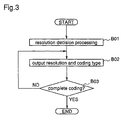
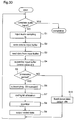
- Figure 3 is a flowchart illustrating a processing procedure in a coding parameter decision means of the video coding apparatus according to the embodiment 1.
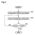
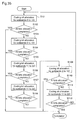
- Figure 5 is a flowchart illustrating a processing procedure in the parameter decision means of the video coding apparatus according to the embodiment 2.
- Figure 6 is a block diagram illustrating a structure of a video coding apparatus according to an embodiment 3 of the present invention.
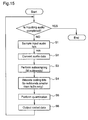
- Figure 12 is a flowchart illustrating a processing procedure of audio coding in the coding apparatus according to the embodiment 5.
- Figure 16 is a block diagram illustrating a structure of an audio coding apparatus according to an embodiment 7 of the present invention.
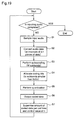
- Figure 19 is a flowchart illustrating a processing procedure of audio coding in the apparatus according to the embodiment 8.
- Figure 23 is a block diagram illustrating a structure of an audio coding apparatus according to an embodiment 10 of the present invention.
- Figure 24 is a flowchart illustrating a processing procedure of audio coding in the apparatus according to the embodiment 10.
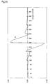
- Figure 25 is a diagram illustrating a coefficient Ci in an operation formula of basic low-pass filter in subsampling according to the embodiment 10.
- Figure 27 is a flowchart illustrating a processing procedure of audio coding in the apparatus according to the embodiment 11.
- Figure 34 is a flowchart illustrating a processing procedure of audio coding in the apparatus according to the embodiment 14.
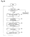
- Figure 36(a) to (c) are flowcharts illustrating a processing procedure of bit allocation to each subband in the sequential bit allocation according to the embodiment 14.
- Figure 45 is a diagram illustrating an operation of the video and audio coding apparatus according to the embodiment 18.
- Figure 52 is a diagram illustrating a schematic structure of a video and audio coding apparatus according to an embodiment 23 of the present invention.
- Figure 60 is a flowchart illustrating a processing procedure of the first audio coding apparatus.
- Figure 66 is a diagram illustrating a minimum audible limit of auditory sense of human being which is applied to psychoacoustic analysis according to a prior art.
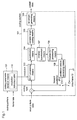
- FIG. 1 is a block diagram illustrating a structure of a video coding apparatus according to a first embodiment of the present invention.
- the video coding apparatus according to the first embodiment comprises a coding section 1 and a coding parameter decision means 102.
- the coding section 101 includes a DCT processing means 103, a quantization means 104, a variable length coding means 105, a bit stream generating means 106, an inverse-quantization means 107, an inverse DCT processing means 108, and a predictive video generation means 109.
- the coding parameter decision means 102 includes a resolution reference table 110.
- the coding section 101 includes a DCT processing means 103, a quantization means 104, a variable length coding means 105, a bit stream generating means 106, an inverse-quantization means 107, an inverse DCT processing means 108, and a predictive video generation means 109.
- the coding parameter decision means 102 includes a resolution reference table 110.
- the coding section 101 is used for inputting video data in which video is digitized and which comprises a series of still pictures as input picture data and for performing coding according to the set coding parameters to output coded data.
- Individual still picture data constituting input picture data is referred to as a frame picture.
- the coding parameters are given by the coding parameter decision unit 102 mentioned later and comprises a parameter indicating a coding type and a parameter indicating a resolution.
- the parameter indicating a coding type indicates an intra frame coding or forward predictive coding.
- the coding section 101 is used for performing the intra frame coding or forward predictive coding according to the parameters.
- the parameter indicating a resolution is input to the DCT processing means 103 and coding is performed in the resolution.
- the coding parameter decision means 102 is used for deciding resolution using a resolution reference table 110 included therein on the basis of a specified frame rate and coding pattern and for outputting the coding parameters including the parameter indicating the decided resolution to the coding section 101.
- step A01 decision on a coding parameter that is input from the coding parameter decision means 102 is performed.
- step A02 processing in subsequent steps including step A02 is carried out and, when forward predictive coding is instructed,
- step B processing in subsequent steps including step A07 is carried out.
- step A05 the bit stream generating means 106 generates a bit stream (coded result) using the variable length coded data which is output from the variable length coding means 105 and the resolution and the coding type which are output from the coding parameter decision means 102, and outputs the bit stream as an output of the video coding apparatus.
- steps A02 to A06 or steps A07 to A14 are performed to each input frame picture.
- steps A02 to A06 intra-frame coding is performed.
- steps A07 to A14 forward predictive coding is performed on the basis of the prediction picture using the coded result of the previous frame picture. Switching between them is performed according to input coding parameters in the decision step A01.
- TABLE 1 shows a resolution reference table 110 included in the coding parameter decision means 102.
- Figure 3 is a flowchart illustrating an operation of the coding parameter decision means 102. An operation of the coding parameter decision means 102 which decides coding parameters and outputs the same to the coding section 101 is described with reference to TABLE 1 and following a flow in Figure 3.
- the resolution reference table 110 in TABLE 1 is created prior to coding.
- the table is created on the basis of empirical knowledge or using a result of experimental coding or simulation, allowing for conditions mentioned later.
- "input” is represented by set frame rates and specified parameters and "output” is represented by parameters decided in response to input.
- resolution is decided in accordance with the frame rates and the coding patterns.
- the frame rate is "24 (frame/sec)" and the coding pattern includes PATTERN 1 "II” and PATTERN 2 "IP", the PATTERN 1 "II” indicating that intra-frame coding (I) is performed to every frame picture and PATTERN 2 "IP” indicating that intra-frame coding (I) and forward predictive coding (P) is repeated every two frames.
- the resolution reference table 110 is created so that coding is carried out using as high resolution as possible, allowing for these conditions and simultaneously realizing the specified frame rate.
- step B02 the coding parameter decision means 102 outputs the resolution and the coding type (I or P) for the frame picture to be processed, which are decided in step B01 to the coding section 101 so that the specified coding pattern is realized.
- TABLE 2 shows resolution (decided parameter) decided by the coding apparatus according to the first embodiment 1 and a frame rate (coded result) obtained using the parameter.
- coded result As a value of coded result in TABLE 2, based on the fact that processing is performed in 24 frames /sec when resolution is "320 x 240" and the coding pattern is "II", another frame rate is computed.
- a coding type (pattern) or resolution has been decided, without allowing for the frame rate as the coded result. Therefore, in some cases, it is difficult to set the frame rate to be close to a desired one and setting of an undesired value is only selected.
- resolution is decided in accordance with the specified coding type (pattern) allowing for the frame rate as the coded result, thereby as shown in contrast between TABLE 2 and TABLE 3, the frame rate which is close to the specified frame rate is realized and simultaneously coding is carried out in higher resolution.
- the apparatus comprises the coding section 101 and the coding parameter decision means 102 including the resolution reference table.
- the coding parameter decision means 102 decides resolution according to the specified frame rate and coding type and outputs the coding parameters to the coding section 101, which performs coding according to the coding parameters. As a result, it is possible to carry out coding in higher resolution, realizing requirements.
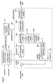
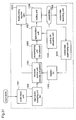
- FIG. 4 is a block diagram illustrating a structure of the video coding apparatus according to the second embodiment of the present invention.
- the video coding apparatus according to the second embodiment comprises a coding section 201, a coding parameter decision means 202, and a processing capability decision means 211, the coding section 201 including a DCT processing means 203, a quantization means 204, a variable length coding means 205, a bit stream generating means 206, an inverse-quantization means 207, an inverse-DCT processing means 208, and a prediction picture generating means 209 and the coding parameter decision means 202 including a coding pattern reference table 210.
- the coding section 201 is identical to the coding section 101 of the video coding apparatus according to the first embodiment.
- the coding section 201 performs coding to the input frame picture in specified resolution and the specified coding type (intra-frame coding (I)) or forward predictive coding (P)) in accordance with coding parameters which are input from the coding parameter decision means 102.
- I intra-frame coding
- P forward predictive coding
- the coding parameter decision means 202 is used for deciding coding parameters according to a decision result of the processing capability decision means 211 and outputting the coding parameters to the coding section 201.
- the processing capability decision means 211 is used for deciding coding processing capability of the coding apparatus and outputting the decision result to the coding parameter decision means 202.
- the processing capability decision means 211 is used for outputting "CPU operating frequency" indicating processing capability of the coding apparatus.
- the coding parameter decision means 202 is used for deciding coding patterns based on the specified frame rate, resolution and the operating frequency as the decision result and posting the coding type to the coding section 201 according to the coding pattern. To decide the coding pattern, the coding parameter decision means 202 uses the coding pattern reference table 210.
- a coding program is executed in PC and conditions (1) to (5) occur as in the first embodiment.
- the operating frequency of CPU, the frame rate specified at the beginning of coding, and resolution of the input frame picture are 100 MHz or 166 MHz, 24 frames/sec, and 320 x 240 or 160 x 120.
- Input picture data is input for each frame picture and coded by the coding section 201.
- the operation of the coding section 201 is identical to that of the coding section 101 shown in the first embodiment.
- the processing capability decision means 211 detects the operating frequency of CPU on PC in which the coding apparatus is realized to decide processing capability of the apparatus and posts the decision result to the coding parameter decision means 202.
- the decision result indicating 100 MHz or 166 MHz is input.
- the coding parameter decision means 202 decides coding parameters using the decision result.
- the coding pattern reference table 210 in TABLE 4 is created prior to coding allowing for conditions mentioned later.
- the reference table is created allowing for the following conditions.
- step C02 the coding parameter decision means 202 outputs the coding parameters to the coding section 201.
- the coding parameter decision means 202 outputs the coding type (I or P) so that the coding pattern in decision step C01) is realized and the specified resolution to the coding section 201.
- step C03 it is decided that coding is completed or not. When it is decided that the coding is completed, processing terminates. Otherwise, processing is returned to step C02 and the coding parameter is output to the coding section 201 again.
- the amount of coded data is represented by amount of coded data corresponding to a frame picture in the coded data, assuming that amount of data of an input frame picture is 1. The less the coded data is, the higher the compression ratio is.
- An advantage of possibility of handling variations of hardware capability of the coding apparatus is useful in realizing the video coding apparatus by running the video coding program in computers or the like.
- coding parameters are decided on the basis of the set frame rate in accordance with processing capability of the coding apparatus and processing capability is decided on the basis of required processing time.
- FIG. 6 is a block diagram illustrating a video coding apparatus according to a third embodiment of the present invention.
- the video coding apparatus according to the third embodiment comprises a coding section 301, a coding parameter decision means 302, and a processing capability decision means 311, the coding section 301 including a DCT processing means 303, a quantization means 304, a variable length coding means 305, a bit stream generating means 306, an inverse-quantization means 307, an inverse-DCT processing means 308, and a prediction picture generating means 309 and the coding parameter decision means 302 including a coding pattern decision means 310.
- the coding parameter decision means 302 is used for deciding coding parameters according to a decision result of the processing capability decision means 311 and using the coding pattern decision means 310 and outputting the coding parameters to the coding section 301.
- the processing capability decision means 311 is used for deciding coding processing capability of the coding apparatus and outputting the decision result to the coding parameter decision means 302. In this embodiment 3, the processing capability decision means 311 is used for outputting an average frame rate in coding as decision result.
- the coding parameter decision means 302 is used for deciding coding patterns based on the specified frame rate and resolution, and the average frame rate, and outputting the coding type to the coding section 301 according to the coding pattern. To decide the coding pattern, the coding parameter decision means 302 uses the coding pattern decision means 310.
- Input picture data is input for each frame picture and coded by the coding section 301.
- the operation of the coding section 301 is identical to that of the coding section 101 shown in the first embodiment.
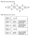
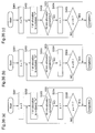
- transition from S3 to S0 in Figure 7(a) increases the ratio of intra-frame coding in which processing burden is small
- transition from S0 to S3 increases ratio of forward predictive coding in which processing burden is large.
- the required time and the output of the processing capability decision means 311 are identical to those in TABLE 8.
- the coding pattern decision means 310 transitions between states and outputs the coding pattern according to its state.
- the coding parameter decision means 302 outputs the coding type of each frame picture according to the output coding pattern as shown in TABLE 9.
- the coding pattern decision means 310 Since the coding pattern decision means 310 initially assumes S1, the coding pattern "IIIP" shown in TABLE7 is output. In response to it, the coding parameter decision means 302 outputs "I”, “I”, “I”, and "P" for the first 4 frame pictures.
- the apparatus comprises the coding section 301, the coding parameter decision means 302 including the coding pattern decision means 310, and the processing capability decision means 311.
- the coding pattern is decided in accordance with the specified resolution.
- resolution may be decided in accordance with the specified coding pattern. As a result, it is possible to perform coding in higher resolution in the required frame rate and coding pattern.
- the buffer means 412 is used for temporarily storing input picture data, sequentially preserving the input picture data as a series of frame picture data l and sequentially abandoning the frame picture read by the coding section 401.
- a coding program is executed in PC and conditions (1) to (5) occur as in the first embodiment.
- the operating frequency of CPU the frame rate specified at the beginning of coding, and resolution of the input frame picture are 100 MHz, 8 frames/sec, and 320 x 240.
- the buffer means 412 sequentially preserves frame pictures input from the input frame rate control means 413 and sequentially abandons the frame picture read by the coding section 401. That is, data is temporarily stored on a first-in, first-out (FIFO) basis.
- FIFO first-in, first-out
- the processing capability decision means 411 detects the number of frame pictures preserved in the buffer means 412, obtains the difference between the number of frame pictures in the initial state buffer means 412 which are previously detected and preserved, and posts the difference to the coding parameter decision means 402.
- the processing capability decision means 411 detects the number of frame pictures preserved in the buffer means 412, obtains the difference between the number of frame pictures in the initial state buffer means 412 which are previously detected and preserved, and posts the difference to the coding parameter decision means 402.
- a positive value is posted thereto and when it is not, a negative value is posted thereto, every time the coding section 401 processes 4 frame pictures.
- the coding pattern decision means 410 assumes 4 states (S0 to S3) and in respective states, outputs the coding pattern in TABLE 11.
- state coding pattern S0 IIII S1 IIIP S2 IPIP S3 IPPP "IIII", “IIIP”, “IPIP” and “IPPP” in TABLE 11 is identical to those in TABLE 7 of the third embodiment.
- State transition of the coding parameter decision means 410 is decided every time the coding section 401 processes 4 frame pictures. The decision is performed following conditions shown in Figure 9(b) on the basis of the difference immediately before the decision that is posted from the processing capability decision means 411. In this fourth embodiment, assume that initialization of state as the infinite state machine is S1.
- the coding parameter decision means 402 obtains the coding pattern output from the coding section 401 and outputs the coding type to the coding section 401 for each frame picture so that the obtained coding pattern is realized, every time the coding section 401 processes 4 frame pictures.
- the coding parameter decision means outputs the specified resolution to the coding section 401.
- transition S1 to S0 occurs as shown in Figure 9(a), thereby the coding pattern in TABLE 12 is changed into "IIII". As a result, only intra-frame coding is performed.
- the specified frame rate is set "8" in a fixed way.
- the coding pattern, required time, the number of inputs, the number of outputs, and output of the processing capability decision means 411 are respectively represented by values of processing every 4 frame pictures (for example, 0th to 3rd frame pictures, 4th to 7th frame pictures).
- the coding pattern, the required time, the number of inputs, and the number of outputs indicate a coding pattern for use in coding every 4 frame pictures, time (second) for coding 4 frame pictures in the coding section 301, the number of frame pictures input to the buffer means 412, and the number of frame pictures 412 output from the buffer means 412, respectively.
- Coded results of 28 frame pictures indicate the average frame rate and amount of coded data.
- Amount of coded result of a frame picture is computed from the fact that 1/10 data is obtained in I coding and 1/60 data is obtained in P coding.
- TABLE 13 shows functions of the coding pattern decision means 410 and the coding parameter decision means 402 in the video coding apparatus according to the third embodiment.
- status of the video coding apparatus according to the fourth embodiment is shown, including outputs of the coding pattern decision means 410 and the coding parameter decision means 402 of each frame picture of 12 frame pictures (0th to 11th) of 28 frame pictures to be processed in TABLE 12.
- the required time, the number of inputs, the number of outputs, and the output of the processing capability decision means 411 are identical to those of TABLE 12.
- the coding pattern decision means 410 transitions between states described above and outputs the coding pattern.
- the coding parameter decision means 302 outputs the coding type for each frame picture according to the output coding pattern.
- the coding pattern "IPIP” is output since the coding pattern decision means 410 transitions from S1 to S2. Therefore, the output of the coding parameter decision means 402 is "I”, “P", “I”, and "P".
- a coding type (pattern) or resolution has been decided, without allowing for the frame rate as the coded result or variation of hardware capability as shown in TABLE 10 in the third embodiment. Therefore, in some cases, it is difficult to set the frame rate to be close to a desired one and setting of an undesired value is only selected.
- the coding type (pattern) is decided in accordance with the specified resolution allowing for the processing capability of the coding apparatus or the frame rate as the coded result, thereby as shown in contrast between TABLE 13 and TABLE 10, the frame rate which is close to the specified frame rate is realized and simultaneously coding is carried out in higher resolution.
- time required for processing must be measured. In this fourth embodiment, if it is impossible or difficult to measure processing time, it is possible to decide processing capability of the apparatus as an indicator of amount of temporarily stored data.
- the apparatus comprises the coding section 401, the coding parameter decision means 402 including the coding pattern decision means 410, the processing capability decision means 411, the buffer means 412, and the input frame rate control means 413.
- the input frame rate control means 413 inputs the input picture data to the buffer means 412 at a give rate, which temporarily stores the input picture data.
- the processing capability decision means 411 outputs the decision result indicating processing capability of the coding apparatus.
- the coding parameter decision means 402 decides the coding pattern in accordance with the specified frame rate and resolution, and decision result output from the processing capability decision means 411, outputs the coding parameter to the coding section 401, which performs coding according to the coding parameter. As a result, it is possible to carry out coding in higher resolution, realizing requirements.
- the video coding apparatus has somewhat more burden, compared with those of the first and second embodiments.
- appropriate coding conditions can be set according to the change.
- the video coding methods shown in the first to fourth embodiments are realized by using a recording medium which records a video coding program which may execute the method and by executing the program in a personal computer or in a work station.
- An audio coding apparatus can reduce the burden of processing by subjecting sampled audio data to conversion processing.
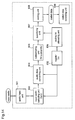
- FIG 10 is a block diagram illustrating the structure of the audio coding apparatus according to the fifth embodiment of the present invention.
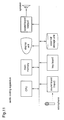
- Figure 11 is a diagram illustrating the hardware structure of the coding apparatus of the fifth embodiment.
- this audio coding apparatus comprises: an audio input unit 501; a register 502; an input audio sampling unit 503; an audio data converting unit 504; a subsampling unit 505; a coding bit allocating unit 506; a quantizing unit 507; a coding unit 508; and a coded data recording unit 509.
- the audio input unit 501 does input of audio as a coding object. Audio may be input through a microphone as shown in figure 11, or through lines.
- the register 502 is implemented by a main memory or an external storage unit shown in figure 11 and stores constants used for coding processing.
- the input audio sampling unit 503 is implemented by a sound board (input) of figure 11 and a control program and performs sampling processing to the audio input through the input unit 501.
- the audio data converting unit 504 puts the data which the input audio sampling unit 503 subjected to sampling processing, through conversion processing using the value of the constant stored in the register 502.
- the subsampling unit 505 subsamples the data converted by the audio data converting unit 504.
- the coding bit allocating unit 506 allocates coding bits to the subbands formed by the subsampling unit 505.
- the quantizing unit 507 performs quantizing processing according to the number of the coding bits allocated by the coding bit allocating unit 506.
- the coding unit 508 outputs the quantized value output from the quantizing unit 507 as coded audio data.
- the respective units 504 to 508 are implemented by the CPU and main memory of figure 11 and a program.
- conversion constant n has a value "2" which is predetermined according to the CPU performance, and the value is stored in the register 502.
- the value of the conversion constant n may be determined by any of the following methods: a method of assuming a specified CPU in the apparatus and performing the setting based on the coding throughput of the CPU; a method of selecting the value of the constant from among the values obtained by simulation for each CPU, according to CPU selection by user; and a method of performing an operation for evaluating the coding throughput of the CPU before coding processing and performing the setting based on the result.
- Figure 12 is a flow chart of the operation of the audio coding by the coding apparatus of the fifth embodiment.
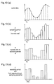
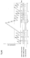
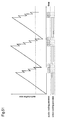
- Figure 13 is a diagram for explaining the sampling and subsequent conversion of audio data performed by the coding apparatus of the fifth embodiment. The operations involved in the coding by the audio coding apparatus of the fifth embodiment will be described with reference to the flow chart of figure 12, and additional reference to figures 10 and 13.
- step 1 of the flow of figure 12 the audio signal input by the audio input unit 501 is sampled by the input audio sampling unit 503, with a set frequency fs as a sampling frequency.
- this sampling is performed in the manner shown in figure 13(a) with a time ts which is a reciprocal of the sampling frequency fs, and m pieces of sampled audio data are output thereby.
- the audio data converting unit 504 obtains the conversion constant n stored in the register 502 and extracts data from the m pieces of sampled audio data output from the input audio sampling unit 503, at intervals of (n-1) pieces of data, to obtain m/n pieces of sampled audio data in total.
- (n-1) is 1 and thus plural pieces of sampled audio data, to which white circles are given in figure 13(b), are extracted at intervals of one piece of data.
- the audio data converting unit 504 forms m pieces of converted audio data in total consisting of contiguous groups of n pieces of extracted data. These pieces of converted audio data, which have a structure shown in figure 13(c), are output as m pieces of audio data having a frequency fs.
- step 4 the coding bit allocating unit 506 obtains the set frequency fs and the conversion constant n from the register 502 and, based on these values, limit frequency fs/2n is calculated which is a minimum frequency allowing reproduction using a generally known sampling constant. Then, each number of allocated coding bits is determined on the assumption that among the m subbands, it is the subbands whose respective frequencies are less than the limit frequency allowing reproduction to which coding bits are allocated and no coding bits are allocated to the subbands whose respective frequencies exceed the limit frequency. The number of allocated coding bits is sent from the coding bit allocating unit 506 to the quantizing unit 507.
- step 5 the quantizing unit 507 quantizes audio data for each subband according to its number of allocated coding bits and in step 6, the coding unit 508 outputs coded audio data based on the quantized value.
- the output coded audio data is recorded in the coded data recording unit 509. As shown in the flow of figure 12, the above-described steps are repeated as long as audio is input as coding object, and coding is completed immediately after the completion of the input of the audio.
- the formulas (1) and (2) are normally operated for m pieces of audio data, but, when the operations are performed for converted audio data comprising contiguous groups of n pieces of sampled audio data obtained by extraction, n pieces of audio data in each group are identical one another and thus the operations for m/n pieces of audio data may be performed to the portion of the converted audio data which comprises contiguous pieces of sampled audio data. Therefore, the amount to be calculated by the formula (1) can be reduced to 1/n, and the amount to be calculated by the formula (2) can be also reduced to 1/n.
- n 4.
- the four values Z0, Z1, Z2, and Z3 are obtained by only one calculation and all values of Zi can be obtained with a quarter of the amount to be calculated.
- the other Xs are converted into audio data array which consists of contiguous groups of three Xs of equal value and, using the converted audio data, the formulas (1) and (2) for subsampling in step 3 are performed. This can reduce the amount to be calculated to approximately one-third.
- the amount to be calculated does not change after conversion of audio data.
- coding bits are allocated to subbands less than limit frequency fs/2n.
- the reason is that, since in the conversion of audio data in step 2, extracting the audio data sampled with sampling frequency fs, at intervals of (n-1) pieces of audio data, is equal to sampled audio data with sampling frequency fs/n, coding objects are limited to the subbands less than reproducible limit frequency fs/2n because of a fact based on a well-known sampling theorem that the frequency band exceeding the reproducible limit frequency fs/2n cannot be reproduced. Since coding bits are not allocated to the subbands exceeding the limit frequency, the quantization for such bands are not needed and the burden of quantization processing in step 5 is reduced to 1/2n.
- the audio coding apparatus of the fifth embodiment comprises the register 502 and the audio converting unit 504, and the audio data converting unit 504, based on the conversion constant, extracts m/n pieces sampled audio data in total, at intervals of (n-1) pieces of the data, from m pieces of sampled audio data which have been obtained by sampling with a set frequency by the audio sampling unit 503 to obtain m pieces of converted audio data each comprising contiguous groups of n pieces of sampled audio data. Therefore, the amount to be calculated in the subsequent process performed by the subsampling unit 505 can be reduced greatly and even the coded data capable of being reproduced with original set frequency can be obtained unlike the case of reducing audio data by extraction.
- the converted audio data is formed which comprises contiguous sampled audio data
- the same effects are available by inserting, between adjacent pieces of sampled audio data, n-1 pieces of appropriate audio data such as the audio data which is the average of adjacent pieces of sampled audio data.
- FIG 14 is a block diagram illustrating the structure of the audio coding apparatus according to the sixth embodiment of the present invention.
- the audio coding apparatus comprises: an audio input unit 601; a register 602; an input audio sampling unit 603; an audio data converting unit 604; a subsampling unit 605; a coding bit allocating unit 606; a quantizing unit 607; a coding unit 608; and a coded data recording unit 609.
- the hardware structure of the coding apparatus of the sixth embodiment is equal to that of the coding apparatus of the fifth embodiment shown in figure 11.
- the audio data converting unit 604 is different from the audio data converting unit 104 of the first embodiment in that this apparatus does not extract sampled audio data but just insert audio data to form converted audio data.
- the audio input unit 601, the subsampling unit 605, the coding bit allocating unit 606, the quantizing unit 607, the coding unit 608, and the coded data recording unit 609 are equal to the respective units 501 and 505 ⁇ 509 in the fifth embodiment.
- Figure 15 is a flow chart illustrating the operation of audio coding by the coding apparatus of the sixth embodiment. Also for the six embodiment, figure 13 is used for explaining sampling and audio data conversion processing. Hereinafter a description is given of the coding operation of the audio coding apparatus according to the sixth embodiment with reference to the flow chart of figure 15, and additional reference to figure 14. As in the fifth embodiment, it is assumed that the set frequency is 48 KHz which is a value defined by MPEGAudio and the conversion constant n is 2.
- step 1 of the flow of figure 15 the input audio sampling unit 603 obtains a set frequency fs and a conversion constant n from the register 602 to decide an executive sampling frequency fs/n.
- the audio signal input from the audio input unit 601 is sampled with the executive sampling frequency fs/n by the input audio sampling unit 603.
- m/n pieces of sampled audio data like data C of figure 13 (d) are output.
- the audio data converting unit 604 obtains a conversion constant n from the register 602 and forms m pieces of converted audio data comprising contiguous groups of n pieces of sampled audio data, on the basis of m/n pieces of sampled audio data output from the input audio sampling unit 603.
- the converted audio data which has a structure of data B of figure 13(c), is output as m pieces of audio data with the frequency fs.
- the audio data like the data C of figure 13(c) cannot be reproduced with a sampling period fs, but the coded data reproducible with the sampling period fs can be obtained by converting this audio data to form the data B of figure 13(c).
- the converted audio data obtained in step 2 is equal to the converted audio data obtained in step 2 of the fifth embodiment and thus the following steps 3 to 6 are executed in the same way as steps 3 to 6 of the fifth embodiment. Then, steps 1 to 6 are repeated as long as audio is input and coding is completed immediately after the completion of inputting audio.
- the audio coding apparatus of the sixth embodiment comprises the register 602, the input audio sampling unit 603, and the audio data converting unit 604, and in this apparatus, the input audio sampling unit 603 decides an executive sampling frequency fs/n based on a set frequency fs and a conversion constant n stored in the register 602 and performs sampling processing, and the audio data converting unit 604 inserts audio data into resultant m/n pieces of sampled audio data to obtain converted audio data which comprises m pieces of audio data. This reduces the processing burden of this apparatus as in the fifth embodiment.
- the buffer memory for temporarily storing input audio data which has been subjected to sampling may be employed having a capacity as large as only one-n th of that in the fifth embodiment, and a soundboard whose maximum sampling frequency is less than fs may be employed, thereby realizing real-time coding processing for input audio by effectively utilizing the relatively small hardware resource of this apparatus.
- An audio data coding apparatus can perform coding according to surrounding situation by changing a conversion constant corresponding to the amount of input data.
- FIG 16 is a block diagram illustrating the structure of the audio coding apparatus according to the seventh embodiment of the present invention.
- this audio coding apparatus comprises: an audio input unit 701; a register 702; an input audio sampling unit 703; an audio data converting unit 704; a subsampling unit 705; a coding bit allocating unit 706; a quantizing unit 707; a coding unit 708; a coded data recording unit 709; an input buffer 7010; and an input buffer supervising unit 7011.
- This structure is equal to that of the audio coding apparatus of the fifth embodiment to which the input buffer 7010 and the input buffer supervising unit 7011 are added.
- the hardware structure of the coding apparatus of the seventh embodiment is also equal to that of the coding apparatus of the fifth embodiment shown in figure 11.
- the input buffer 7010 is implemented primarily by a memory such as a main memory and stores data temporarily.
- the input buffer supervising unit 7011 is implemented by a CPU, a main memory and a program, and this unit checks the amount of the data held in the input buffer 7010 for temporary storage to make a comparison between the amount of this data and a predetermined value, and then changes a conversion constant n in the register 702 according to the result of the comparison.
- the register 702 is identical to the register 502 of the fifth embodiment except that the value of the stored conversion constant is changed by the input buffer supervising unit 7011.
- the input audio sampling unit 703 is identical to the input audio sampling unit 503 of the fifth embodiment except that this unit outputs the sampled audio data to the input buffer 7010.
- the audio data converting unit 704 is identical to the audio data converting unit 504 of the fifth embodiment except that this unit takes sampled audio data from the input buffer 7010 as processing object. Moreover, the audio input unit 701, the subsampling unit 705, the coding bit allocating unit 706, the quantizing unit 707, the coding unit 708, and the coded data recording unit 709 are identical to the respective units 501 and 505 ⁇ 509 of the fifth embodiment.
- a set frequency fs is 48 KHz, which is a frequency defined by MPEGAudio
- a conversion constant n takes an initial value 1 which is predetermined according to the CPU performance and this value is stored in the register 702.
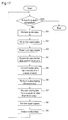
- step 1 of the flow of figure 17 the audio signal input from the audio input unit 701 is sampled by the input audio sampling unit 703 as in the fifth embodiment and, in step 2, the sampled audio data is written into the input buffer 7010 and temporarily stored.
- step 3 th audio data converting unit 704 reads the temporarily stored, sampled audio data from the input buffer 7010.
- step 5 of converting audio data to step 9 of outputting coded data are executed in the same way as steps 2 to 6 of the flow of figure 12 and thus a description of the operation in steps 5 to 9 will be omitted.
- step 4 the input buffer supervising unit 7011 checks the amount of the data held in the input buffer 7010 to make a comparison between this amount of data and a predetermined value, and, according to the result of the comparison, changes a value of a conversion constant n which is stored in the register 702.
- Various methods can be used for supervising the input buffer to control the value of the conversion constant n and in this case, the following method is employed.
- reading for coding processing from the input buffer 7010 is performed at lessened rate although writing to the same buffer is performed at a fixed speed, resulting in increased amount of data.
- step 5 data is sampled at intervals of one piece of data to convert the data into a form which consists of contiguous groups of two pieces of data of a same value, and in step 6, the data of such form is subsampled, whereby a part of the subsampling processing in step 6 can be reduced to one-second.
- step 7 coding bits are allocated only to the subbands less than a frequency fs/4 while coding bits are allocated to every subband in the other cases, thereby reducing the quantization processing in step 8.
- the input buffer supervising unit 7011 can reduce the burden of the CPU by changing the value of the conversion constant n.
- the data is sampled at intervals of two pieces of data such that the data comprises contiguous groups of three pieces of data of same value, whereby the part of the subsampling processing in step 6 is reduced to one-thirds, and at the allocation of coding bits to the respective subbands in step 7, it is the subbands less than the frequency fs/6 to which coding bits are allocated, resulting in reduction of quantization processing to one-sixth.
- the input buffer supervising unit 7010 continues to increase the value of the constant n in the register 2 until the amount of data in the input buffer 7010 becomes less than the buffer full level BF.
- the input buffer supervising unit 7011 judges that the coding throughput is not exceeded. Since sampling to audio data and cutting high frequency components tend to be avoided with lower conversion constant and thus high-quality coded data can be obtained, the input buffer supervising unit 7011 reduces the value of the conversion constant n by 1 and thereafter, in the repetition of the flow of figure 17, the value of the conversion constant n stored in the register 702 is reduced by 1 until the amount of data in the input buffer 7010 exceeds the buffer empty level BE, as in the above-described case.
- the buffer full level only may be used.
- the value of the conversion constant n is increased until the amount of data in the input buffer reaches a predetermined buffer full level BF and when the audio input becomes equal to the coding processing, that is, the amount of data reaches the BF, control is performed to stop the increment of the conversion constant n.
- the audio coding apparatus of the seventh embodiment has the structure of the audio coding apparatus of the fifth embodiment to which the input buffer 7010 and the input buffer supervising unit 7011 are added. Therefore, sampled audio data is temporarily stored in the input buffer 7010 and then read for the following processing. Further, since the input buffer supervising unit 7011 checks the amount of data held in the input buffer 7010 and performs active control to the value of the conversion constant n stored in the register 702 corresponding to surrounding situation using the checked amount as an indicator for the coding throughput of CPU at this point in time, audio coding of highest quality can be realized which can be performed by the CPU at this point in time.
- the audio coding apparatus can perform coding corresponding to surrounding condition by changing conversion constant in correspondence to an amount of output data.
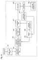
- the coded data supervising unit 8012 is implemented by a CPU, a main memory or a program and checks an amount of coded data per unit time, which data is output from the coding unit 808, and according to the result, changes a value of the conversion constant n in the register 802.
- the register 802 is identical to the register 502 of the fifth embodiment except that the value of the conversion constant stored within it is changed by th coded data supervising unit 8012.
- the audio input unit 801, the input audio sampling unit 803, the audio data converting unit 804, the subsampling unit 805, the coding bit allocating unit 806, the quantizing unit 807, the coding unit 808, and the coded data recording unit 809 are equal to the respective units 501 and 503 to 509 of the fifth embodiment.
- Figure 19 is a flow chart illustrating the operation of the audio coding performed by the coding apparatus of the eighth embodiment.
- the coding operation by the audio coding apparatus of the eighth embodiment will be described with reference to figure 19, and additional reference to figure 18.
- sampling frequency fs is 48 KHz which is a frequency defined by MPEGAudio.
- conversion constant n takes an initial value "1" predetermined corresponding to the CPU performance and the value is stored in the register 802.
- step 7 when the amount of coded data does not reach a lowest coding level CL, the coded data supervising unit 8012 increases the value of the conversion constant n in the register 802 to reduce the burden of the CPU, as in the case of the input buffer supervising unit 7011 of the seventh embodiment.
- the coded data supervising unit 8012 in the eighth embodiment continues to change the value of the conversion constant n until the amount of coded data is judged as a being suitable.
- the input audio sampling unit obtains m pieces of sampled audio data by sampling with a sampling frequency fs, and then the audio data converting unit performs sampling to the sampled audio data at intervals of (n-1) pieces of data according to the fifth embodiment
- the input audio sampling unit may perform sampling with a sampling frequency fs/n to obtain m/n pieces of sampled audio data and then the audio data converting unit converts this data to obtain m pieces of converted audio data as in the sixth embodiment, which can be executed easily by changing the setting in software.
- the same effects explained in the sixth embodiments are available including reduction in capacity of buffer memory and use of sound board which imposes restrict limit on sampling frequency.
- coding processing can be performed using CPU of any performance level.
- CPU of higher performance can realize high-quality coding, and a sound board of higher capability, and a faster data transmission rate within the apparatus enables high-quality coding of higher quality.
- audio coding performed in the fifth to eighth embodiments may be recorded in a recording medium as an audio coding control program and implemented using personal computer, workstation, and other units.
- coding processing is performed using CPU, this processing may be implemented in software, using DSP in place of CPU.
- Figure 20 is a block diagram illustrating a structure of the audio coding apparatus according to the ninth embodiment.
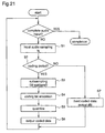
- Figure 21 is a flowchart of audio coding according to the ninth embodiment.
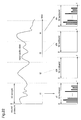
- Figure 22 is a conceptual diagram for explaining audio coding according to the ninth embodiment.
- Hardware of the ninth embodiment is identical to that of the fifth embodiment and is described with reference to Figure 11.
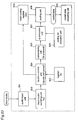
- the audio coding unit comprises an audio input unit 901, a register 902, an input audio sampling unit 903, a decision control unit (decide an unit period) 904, a subsampling unit 908, a coding unit 908, a coded data recording unit 909, and a fixed coding register 910.
- the audio input unit is used for inputting audio to be coded. Audio may be input from the microphone as shown in Figure 11 or may be line input.
- the unit period decision constant register 902 is realized in the main memory in Figure 11 or in an external Storage device and used for storing an unit period decision constant.
- the input audio sampling unit 903 is realized in the sound board (input) in Figure 11 and control program and used for sampling the audio input from the audio input unit 901.
- the decision control means 904 is used for deciding whether the data sampled by the input sampling unit 903 is in a coding period or not using a constant stored in the register 902.
- the subsampling unit 905 subsamples sampled data only when it is decided that the data is in the coding period by the decision control means 904.
- the coding bit allocation unit 906 is used for allocating coding bits to subbands divided by the subsampling unit 905.
- the quantization unit 907 performs quantization according to the number of bits allocated by the coding bit allocation unit 906.
- the coding means 908 is used for outputting a quantized value output from the quantization unit 907 as coded audio data.
- the coding unit 908 is used for outputting coded data dN corresponding to subband output zero stored in the fixed coding register 910 as coded audio data.
- the units 904 to 908 are all realized in the CPU, the main memory in Figure 11, and program.
- step 1 in Figure 21 audio signals input from the audio input unit 901 are sampled at a set sampling frequency fs by the input audio sampling unit 903, thereby the data sampled at frequency fs is output to te decision control unit 904.
- the decision control unit 904 decides whether the sampled data is in the coding period or not.
- step 7 when it is decided that the unit period ti is not in the coding period, subsampling, coding bit allocation, and quantization in steps 3 to 6 are not performed, step 7 is performed.
- step 7 the coding unit 908 obtains the fixed coded data dN from the fixed coding register 910 and outputs the same as coded data.
- the fixed coded data dN is preset in the fixed coding register 910 assuming output of each subband in subsampling to be zero.
- the coded audio data is recorded in the coding recording unit 909.
- Sampled data in this unit period is divided into 32 subband signals, quantized and coded, resulting in coded data d1.
- the fixed coded data dN is preset assuming 32 subband signals to be zero.
- a method of deciding the variable constant k may include setting of the constant by assuming fixed CPU for use in the apparatus, selecting the constant by CPU selection of the user among values which have been found in each CPU by performing simulation, or setting the constant on the basis of the result of operation for computing coding processing capability of CPU prior to coding.
- the longer the period is, the more significant degradation of sound is. Therefore, it is desirable to set the period of subband output zero to be 32 samples, that is, k 2. If it is necessary to carry out coding accepting the degradation of sound, real-time coding according to capability of the apparatus is possible by setting k to be larger.
- FIG. 23 is a block diagram illustrating a structure of the audio coding apparatus according to the tenth embodiment.
- the audio coding apparatus comprises an audio input unit 1001, an input audio sampling unit 1003, a subsampling unit 1005, a coding bit allocation unit 1006, a quantization unit 1007, a coding unit 1008, a coded data recording unit 1009, and a register 1011.
- the apparatus of the tenth embodiment has a hardware structure shown in Figure 11.
- the register 1011 is realized in the main memory or the external storage device and used for storing the operation decision constant for use in operation control in subsampling.
- the subsampling unit 1005 of the tenth embodiment includes an operation termination unit for obtaining a value of the operation decision constant from the register 1011 and terminating operation in subsampling.
- the audio input unit 1001, the input audio sampling unit 1003, the coding bit allocation unit 1006, the quantization unit 1007, the coding unit 1008, and the coded data recording unit 1009 are identical to 901, 903, and 906 to 909 and will not be discussed.
- Figure 24 is a flowchart of audio coding in the audio coding apparatus according to the tenth embodiment.
- Figure 25 is a diagram illustrating a coefficient for use in operation of basic low-pass filtering. An operation of the audio coding apparatus of the tenth embodiment is described following Figure 24 and with reference to Figures 23 and 25.
- step 2 sampled data is subsampled by the subsampling unit 1005.
- the basic low-pass filtering is performed. In this basic low-pass filtering, the following formulas (1), (2), and (3) are performed.
- step 2 in Figure 24 after subsampling is performed by omitting a part of operation, resulting subband signals are to be processed. Subsequent steps including step 3 are identical to those of the first prior art and will not be discussed.
- the apparatus comprises the register 1011 for storing the operation decision constant q and the subsampling unit 1005, the subsampling unit 1005 omitting operation of the basic low-pass filtering of a part of samples in subsampling on the basis of the operation decision constant q.
- FIG. 26 is a block diagram illustrating a structure of the audio coding apparatus according to the eleventh embodiment.
- the audio coding apparatus comprises an audio input unit 1101, an input audio sampling unit 1103, a subsampling unit 1105, a coding bit allocation unit 1106, a quantization unit 1107, a coding unit 1108, a coded data recording unit 1109, a register 1112, and a subband reducing unit 1118.
- the apparatus of the eleventh embodiment has a hardware structure shown in Figure 11.
- Figure 27 is a flowchart of audio coding according to the eleventh embodiment.
- Figure 28 is conceptual diagram for explaining audio coding according to the eleventh embodiment. An operation of the audio coding apparatus of the eleventh embodiment is described following Figure 27 and with reference to Figures 26 and 28.
- the subband reducing unit 1118 outputs the extracted M/(r + 1) subband signal data is output to the quantization unit 1107.
- step 4 the coding bit allocation unit 1106 decides the number of coding bits to be allocated only to the subbands extracted in step 3 on the basis of the subband decision constant from the register 1112.
- the decided number of coding bits allocated to M/(r + 1) subbands is sent from the coding bit allocation unit 1106 to the quantization unit 1107.
- Subsequent steps including step 5 is performed to the M/(r + 1) data as in the first prior art example.
- the input buffer 1213 is realized in a memory such as a main memory and used for temporarily storing data.
- the input buffer supervision unit 1214 is realized in CPU, a main memory and a program and used for checking amount of data held in the input buffer 1213, comparing the amount of data with a preset value, and changing the value of constant k of the register 1202 on the basis of comparison result.
- the register 1202 is identical to the register 902 in the ninth embodiment except that the value of constant is changed by the input buffer supervising unit 1214.
- the input audio sampling unit 1203 is identical to the input audio sampling unit 903 in the ninth embodiment except that sampled audio data is output to the input buffer 1213.
- the decision control unit (unit period decision) 1204 is identical to the decision control unit 904 in the ninth embodiment except that sampled audio data is fetched from the input buffer 1213.
- the audio input unit 1201, the subsampling unit 1205, the coding bit allocation unit 1206, the quantization unit 1207, the coding unit 1208, the coded data recording unit 1209, and the fixed coding register 1210 are identical to 901, and 905 to 910 of the ninth embodiment.
- step 1 in Figure 30, audio signals input from the audio input unit 1201 are sampled by the input audio sampling unit 1203 as in the ninth embodiment.
- step 2 sampled data is written onto the input buffer 1213, to be temporarily stored therein.
- step 3 the decision control unit 1204 reads temporarily stored sampled data from the input buffer 1213.
- step 4 subsequent to step 3 the input buffer supervising unit 1214 checks amount of data in the input buffer 1213, compares the amount of data with preset value, and changes the value of constant k stored in the register 1202 on the basis of the comparison result.
- Control of the value of constant k may be performed using various methods. Herein, this is performed as follows.
- steps 5 to 9 subsampling, coding bit allocation, and quantization are not performed to periods t2 and t3 and preset coded data dN is output as subband output 0.
- steps 5 to 9 subsampling, coding bit allocation, and quantization are not performed to periods t2 to t4 and preset coded data dN is output as subband output 0, thereby load on processing is reduced about 1/4. Thereafter, until amount of data in the input buffer becomes not more than BF, the input buffer supervising unit 1214 increases the value of K.
- step 4 when amount of data in the input buffer 1213 is less than buffer empty level BE (preset value), the input buffer supervising unit 1214 decides that CPU has reserve capability. The smaller the constant k is, the more time of subband output 0 is reduced and the higher quality data is obtained. Therefore, the input buffer supervising unit 1214 reduces the value of k by 1 and, until amount of data in the input buffer 1213 becomes not less than BE, the input buffer supervising unit 1214 reduces the value of K by 1 in step 4 in repetition of flow in Figure 30.
- BE buffer empty level
- the audio coding apparatus further comprises the input buffer 1213 and the input buffer supervising unit 1214, compared with the audio coding apparatus of the ninth embodiment.
- the sampled data is temporarily stored in the input buffer 1213 and then read to be processed and the input buffer supervising unit 1214 dynamically controls the value of the unit period decision constant k stored in the register by checking amount of data in the input buffer 1213. Therefore, in addition to real-time coding according to basic performance of CPU, audio coding with the highest quality at that point of time is realized, handling variations of processing capability of CPU.
- the input buffer 1213 and the input buffer supervising unit 1214 are added to the audio coding apparatus of the ninth embodiment.
- these units may be added to the apparatus of the tenth embodiment and, control of the operation decision constant q increases/reduces amount of operation of the basic low-pass filtering. As a consequence, it is possible to reduce processing burden and improve quality of sound of coded data.
- these units may be added to the apparatus of the eleventh embodiment. Control of the subband selecting constant r increases/reduces subband signal data that is selectively extracted. As a consequence, it is possible to reduce processing burden and improve quality of sound of coded data.
- An audio coding apparatus supervises amount of output data and changes a control constant according to the amount of output data.
- FIG 31 is a block diagram illustrating a structure of the audio coding apparatus according to the thirteenth embodiment.
- the audio coding apparatus comprises an audio input unit 1301, a register 1302, an input audio sampling unit 1303, a decision control unit 1304, a subsampling unit 1305, a coding bit allocation unit 1306, a quantization unit 1307, a coding unit 1308, a coded data recording unit 1309, a fixed coding register 1310, and a coded data supervising unit 1315.
- the coded data supervising unit 1315 is added to the structure of the ninth embodiment.
- the apparatus of the thirteenth embodiment has a hardware structure shown in Figure 11.
- Figure 32 is a flowchart illustrating audio coding according to the thirteenth embodiment. An operation of audio coding according to the thirteenth embodiment is described following flowchart in Figure 32 and with reference to Figure 31.
- Steps 1 to 7 in Figure 32 are performed as in the ninth embodiment and will not be discussed.
- subsampling, coding bit allocation, and quantization are performed to unit period t1, t3,.... and these processing are not performed to t2, t4...., thereby coding is realized with reduced processing burden.
- step 8 is performed prior to returning to step 1.
- the coded data supervising unit 1315 checks amount of data per unit of time that is output from the coding unit 1308, compares the amount of data with a preset value, and changes the value of constant k stored in the register 1302 on the basis of the comparison result.
- Supervision of coded data and control of the value of constant k may be performed using various methods. Herein, this is performed as follows.
- step 8 if amount of coded data does not reach the lowest level CL, the coded data supervising unit 1315 increases the value of constant k stored in the register 2, thereby burden on CPU is reduced.
- step 8 when amount of coding per unit time is not lower than the highest level CH, the value of constant is reduced to perform coding with high quality.
- the audio coding apparatus further comprises the coded data supervising unit 1315, compared with the apparatus of the ninth embodiment.
- the coded data supervising unit 1315 dynamically controls the value of the constant k stored in the register 1302 by checking amount of output data per unit of time, the constant k indicating processing capability of CPU. Therefore, audio coding with the highest quality at that point of time is realized by CPU. As a result, as in the twelfth embodiment, it is possible to handle variations of processing capability of CPU at that point of time.
- the coded data supervising unit 1315 may be added to the apparatus of tenth or eleventh embodiment and by controlling the value of operation decision constant or subband selecting constant, the same effects are achieved.
- An audio coding apparatus realizes alternative psychoacoustic analysis control according to a coding bit allocation method, thereby improving playback quality of sound of coded data without exceedingly increasing a processing burden.
- FIG 33 is a block diagram illustrating an audio coding apparatus according to a fourteenth embodiment of the present invention.
- the audio coding apparatus of the fourteenth embodiment comprises an audio input unit 1401, an input audio sampling unit 1403, a subsampling unit 1405, a coding bit allocation unit 1406, a quantizing unit 1407, a coding unit 1408, a coded data recording unit 1409, and a bit allocation (sequential bit allocation) control unit 1416.
- the construction of the apparatus of the fourteenth embodiment is realized by the hardware shown in figure 11, similar to the ninth embodiment.
- Figures 34, 35 and 36(a) ⁇ 36(c) are flow charts showing an audio coding operation according to the fourteenth embodiment of the invention. A description is given of the audio coding operation according to the flow charts shown in figures 34 to 36(c), with reference to figure 33.
- steps S1 and S2 are carried out as in the steps S1 and S2 shown in figure 65 in the second prior art, thereby producing subband signal data that are obtained by dividing sampled data into M pieces of frequency bands.
- M is assumed to be 32 as in the second prior art.
- the sampled data is divided into L (256) pieces of subband signal data, Fast Fourier Transformation (FFT) and psychoacoustic analysis are performed to the subband signal data, and the allocation number of coding bits is determined.
- FFT Fast Fourier Transformation
- the bit allocation control unit 1416 calculates the bit numbers using a sequential bit allocation method as an alternative psychoacoustic analysis control method, and on the basis of the calculated results, the coding bit allocation unit 1406 allocates coding bits to the respective M (32) pieces of subband signal data.
- the total bit number to be allocated is obtained from the bit rates that are respectively defined as 256 kbps in a first layer of the MPEG audio and as 192 kbps in a second layer.
- the obtained total bit number is allocated according to a sequential bit allocation method described as follows.
- Figures 36(a) ⁇ 36(c) are flow charts showing process steps for allocating bits to the respective subbands.
- the process steps shown in figure 36(a) are carried out in the steps S101, S103 and S109 of the flow in figure 35
- the process steps shown in figure 36(b) are carried out in the steps S105, S107 and S111 of the flow in figure 35
- the process steps shown in figure 36(c) are carried out in the step S113 of the flow in figure 35.
- the sequential bit allocation method in the apparatus according to the fourteenth embodiment is a method in which bits are allocated to subbands 0 to 10 and 11 to 22.
- the minimum audible limit is low at the subbands 0 to 10 and 11 to 22, i.e., it is probable to hear with human hearing at these subbands.
- the subbands at which it is probable to hear with human hearing are more weighted, and bits are allocated in order of the weight of the subbands. Consequently, whether each subband has a large sound pressure or has little sound pressure, i.e., basically independent of an input signal, sequential bits are allocated as described above.
- the audio coding apparatus in the audio coding apparatus according to the fourteenth embodiment, there is provided with the bit allocation control unit 1416, and bits are sequentially allocated to subbands according to a specified algorithm. Therefore, without exceedingly increasing a processing burden, coding bit allocation that makes the most of human hearing characteristics can be performed, thereby obtaining coded data having high playback quality of sound. More specifically, the audio coding apparatus of the fourteenth embodiment has a construction in which the bit allocation control unit 1416 is added to the apparatus according to the first prior art, and the simple coding bit allocation according to the simple algorithms shown in figures 35 and 36(a) ⁇ 36(c) is performed to 32 subbands, thereby improving the playback quality of sound.
- FIG 37 is a block diagram illustrating an audio coding apparatus according to a fifteenth embodiment of the present invention.
- the audio coding apparatus of the fifteenth embodiment comprises an audio input unit 1501, an input audio sampling unit 1503, a subsampling unit 1505, a coding bit allocation unit 1506, a quantizing unit 1507, a coding unit 1508, a coded data recording unit 1509, and a bit allocation (subband output adaptive bit allocation) control unit 1517.
- This construction is identical to the construction of the apparatus according to the fourteenth embodiment, and is realized by the hardware shown in figure 11, similar to the ninth embodiment.
- the bit allocation control unit 1517 comprises a CPU, a main memory and a program. M pieces of subband signal data are produced by performing subsampling in the subsampling unit 1505, and the bit allocation control unit 1517 calculates the bit numbers that are allocated to the respective subband signal data by the coding bit allocation unit 1506, according to a specified algorithm.
- the apparatus of the fifteenth embodiment is fundamentally identical to that of the fourteenth embodiment, except for the function of the bit allocation control unit 1517.
- the audio input unit 1501, the input audio sampling unit 1503, the subsampling unit 1505, the coding bit allocation unit 1506, the quantizing unit 1507, the coding unit 1508, and the coded data recording unit 1509 are identical to those which are represented by the numerals 901, 903 and 905 to 909 described for the ninth embodiment, respectively, and no description is given of these units.
- Figure 38 is a flow chart showing an audio coding operation according to the fifteenth embodiment of the invention. A description is given of the audio coding operation according to the flow chart shown in figure 38, with reference to figure 37.
- steps S1 and S2 are carried out as in the steps S1 and S2 shown in figure 62 in the second prior art, thereby producing subband signal data that are obtained by dividing sampled data into M pieces of frequency bands.
- M is assumed to be 32 as in the second prior art.
- the total bit number to be allocated is obtained from the bit rate of 256 kbps in a first layer as in the fourteenth embodiment of the invention.
- the bit allocation control unit 1517 obtains subband output adaptive weight (3) on the basis of two factors to be considered, i.e., weight of subbands at which it is probable to hear with human hearing (1) and subband output level ratio (2), and allocates the obtained total bit number according to the subband output adaptive weight (3).
- the weight of subbands at which it is probable to hear with human hearing (1) is determined on the basis of the minimum audible limit shown in figure 63 as follows (sb: subband).
- bit allocation control unit 1517 determines the bit allocation numbers so that bit allocation of the respective subbands approaches the weight (3), and the coding bit allocation unit 1506 performs coding bit allocation. Then, steps S4 and S5 of the flow shown in figure 38 are carried out as in the second prior art.
- bit allocation control unit 1517 there is provided with the bit allocation control unit 1517, and bits are allocated to the respective subbands on the basis of two factors, i.e., whether the respective subbands are ones at which it is probable to hear with human hearing or not, and sound pressures of the respective subbands. Therefore, without exceedingly increasing a processing burden, coding bit allocation that makes the most of human hearing characteristics can be performed, thereby obtaining coded data having high playback quality of sound.
- the audio coding apparatus of the fifteenth embodiment has a construction in which the bit allocation control unit 1517 is added to the apparatus according to the first prior art, and the simple coding bit allocation using the relatively simple processing is performed to 32 subbands, thereby improving the playback quality of sound.
- the apparatus of the fifteenth embodiment has a far less processing burden, and both of real-time processing and improvement of sound quality are possible when audio coding is performed in a general personal computer, a work station or the like that is realized by the hardware shown in figure 21.
- the audio coding apparatus of the fifteenth embodiment has a more processing burden due to processing on the basis of input audio characteristics, but can obtain coded data having higher playback quality of sound.
- the calculating method in the subband output adaptive bit allocation method described for the fifteenth embodiment is one example. Even when the weight of the subbands and the weight of two factors are changed, the same allocation using the simple processing can be performed with the same effects.
- An audio coding apparatus realizes alternative psychoacoustic analysis control according to a coding bit allocation method, considering output levels and the bit allocation numbers of respective subbands, thereby further improving playback quality of sound of coded data.
- the audio input unit 1601, the input audio sampling unit 1603, the subsampling unit 1605, the coding bit allocation unit 1606, the quantizing unit 1607, the coding unit 1608, and the coded data recording unit 1609 are identical to those which are represented by the numerals 901, 903 and 905 to 909 described for the ninth embodiment, respectively, and no description is given of these units.
- Figures 40 and 41 are flow charts showing an audio coding operation according to the sixteenth embodiment of the invention. A description is given of the audio coding operation according to the flow charts shown in figures 40 and 41, with reference to figure 39.
- steps S1 and S2 are carried out as in the steps S1 and S2 shown in figure 62 in the second prior art, thereby producing subband signal data that are obtained by dividing sampled data into M pieces of frequency bands.
- M is assumed to be 32 as in the second prior art.
- the bit allocation control unit 1517 calculates the bit numbers using a subband output adaptive bit allocation method. In the sixteenth embodiment of the invention, however, the bit allocation control unit 1617 determines the allocation numbers of bits using an improved subband output adaptive bit allocation method. More specifically, in the fourteenth embodiment, bit allocation is performed to the frequency bands that are obtained by dividing the data into 32, without considering the bit numbers allocated to the respective subbands and with the subbands at which it is probable to hear with human hearing given priority.
- bit allocation is performed to the respective subbands on the basis of two factors, i.e., whether the respective subbands are ones at which it is probable to hear with human hearing or not, and sound pressures of the respective subbands.
- bit allocation information of the respective subbands is produced on the basis of two factors described for the fifteenth embodiment and another factor, i.e., whether the bit numbers allocated to the respective subbands are satisfactory or not.
- the total bit number to be allocated is obtained from the bit rate of 256 kbps in a first layer as in the fourteenth and fifteenth embodiments of the invention.
- the bit allocation control unit 1617 allocates the obtained total bit number on the basis of three factors to be considered, i.e., subband output levels (1), weight of subbands at which it is probable to hear with human hearing (2), and weight corresponding to the bit allocation numbers of respective subbands (3).
- the weight of subbands at which it is probable to hear with human hearing (2) is determined on the basis of the minimum audible limit shown in figure 63 as follows. Since the subband output levels are represented as the scale factors, the following values have the reverse sense of the values of the weight described for the fourteenth embodiment.
- the item (1) is initially added to the item (2), thereby obtaining the following bit allocation information coefficients.
- bit allocation control unit 1617 performs bit allocation as described above, at a step S3 of the flow shown in figure 40, with reference to figure 41.
- Figure 41 is a flow chart showing process steps in an improved subband output adaptive bit allocation method.
- the bit allocation control unit 1617 calculates the scale factors of the respective subbands. This processing corresponds to the item (1).
- the bit allocation information coefficients of the respective subbands are calculated by the weighting processing on the basis of the minimum audible limit. This processing corresponds to the item (2).
- the item (1) is added to the item (2). Then, a subband having the smallest bit allocation information coefficient is detected (step S103), and 1 coding bit is allocated to the subband (step S104).
- a step S105 weighting that corresponds to the item (3) is performed. That is, to the subband to which the bit has been allocated in the step S104, there is added a weighting coefficient corresponding to the bit allocation number of the subband, which coefficient is obtained from the table 14.
- the operations in the steps S103 to S105 are repeated until it is judged in a step S106 that allocation of the total bit number has been completed.
- the flow shown in figure 41 is completed.
- the step S3 of the flow shown in figure 40 is completed, followed by steps S4 and S5 as in the second prior art.
- bit allocation control unit 1617 there is provided with the bit allocation control unit 1617, and bits are allocated to the respective subbands on the basis of three factors, i.e., whether the respective subbands are ones at which it is probable to hear with human hearing or not, sound pressures of the respective subbands, and avoidance of allocation of bits more than required to the identical subband. Therefore, without exceedingly increasing a processing burden, coding bit allocation that makes the most of human hearing characteristics can be performed, thereby obtaining coded data having high playback quality of sound.
- the calculating method in the improved subband output adaptive bit allocation method described for the sixteenth embodiment is one example. Even when the weight of the subbands and the weight corresponding to the bit allocation numbers of the subbands are changed, and even using not scale factor values but a subband output level ratio, the same allocation using the simple processing can be performed with the same effects.
- An audio coding apparatus realizes alternative psychoacoustic analysis control according to a coding bit allocation method considering the minimum audible limit, thereby improving playback quality of sound of coded data.
- FIG 42 is a block diagram illustrating an audio coding apparatus according to a seventeenth embodiment of the present invention.
- the audio coding apparatus of the seventeenth embodiment comprises an audio input unit 1701, an input audio sampling unit 1703, a subsampling unit 1705, a coding bit allocation (dynamic bit allocation) unit 1706, a quantizing unit 1707, a coding unit 1708, a coded data recording unit 1709, and a minimum audible limit comparing unit 1718.
- This construction is identical to the construction of the apparatus according to the fourteenth embodiment, and is realized by the hardware shown in figure 11, similar to the ninth embodiment.
- the minimum audible limit comparing unit 1718 comprises a CPU, a main memory and a program. M pieces of subband signal data are produced by performing subsampling in the subsampling unit 1705, and the minimum audible limit comparing unit 1718 compares the subband signal data with the minimum audible limit, and detects subbands not reaching the minimum audible limit.
- the coding bit allocation unit 1706 does not perform coding bit allocation to the subbands that have been detected by the minimum audible limit comparing unit 1718.
- the apparatus of the seventeenth embodiment is fundamentally identical to that of the fourteenth embodiment, except for the function of the minimum audible limit comparing unit 1718.
- the audio input unit 1701, the input audio sampling unit 1703, the subsampling unit 1705, the coding bit allocation unit 1706, the quantizing unit 1707, the coding unit 1708, and the coded data recording unit 1709 are identical to those which are represented by the numerals 901, 903 and 905 to 909 described for the ninth embodiment, respectively, and no description is given of these units.
- Figure 43 is a flow chart showing an audio coding operation according to the seventeenth embodiment of the invention. A description is given of the audio coding operation according to the flow chart shown in figure 43, with reference to figure 42.
- the minimum audible limit comparing unit 1718 stores the minimum audible limit to M (32) pieces of subbands as a table, using a memory or the like as an internal memory means. This table is stored by reading data from a graph shown in figure 66 or numeric representation of this graph.
- the sampled data is divided into L (256) pieces of subband signal data, Fast Fourier Transformation and psychoacoustic analysis including comparison with the minimum audible limit are performed to the subband signal data, and the allocation number of coding bits is determined.
- the minimum audible limit comparing unit 1718 compares M (32) pieces of subbands with the minimum audible limit, and on the basis of the comparison results, the coding bit allocation unit 1706 allocates coding bits to the M pieces of subband signal data.
- the minimum audible limit comparing unit 1718 compares M (32) pieces of subband signal data that are obtained by the division of the subsampling unit 1705, with the minimum audible limit of the subbands corresponding to the table that has been previously stored, and detects subbands not reaching the minimum audible limit to output the same to the coding bit allocation unit 1706.
- a step S4 using the comparison results, the coding bit allocation unit 1706 does not allocate bits to the subbands not reaching the minimum audible limit, and allocates more bits to the other subbands exceeding the minimum audible limit. Then, steps S5 and S6 shown in figure 43 are carried out as in the second prior art.
- the minimum audible limit comparing unit 1718 compares the M pieces of subbands that are obtained by the division of the subsampling unit 1705, with the minimum audible limit that has been previously stored, and detects subbands not reaching the minimum audible limit, and the coding bit allocation unit 1706 does not allocate coding bits to the detected subbands. Therefore, without exceedingly increasing a processing burden, coding bit allocation that makes the most of human hearing characteristics can be performed, thereby obtaining coded data having high playback quality of sound.
- the minimum audible limit table is stored previous to audio coding, the graph shown in figure 66 or numeric representation of this graph is read.
- the minimum audible limit of the respective subbands may be obtained to store the same. Since this table contrasts INDEX with the minimum audible limit, the minimum audible limit is obtained from the table using the values of INDEX close to the respective center frequencies of M (32) subbands.
- the ninth to seventeenth embodiments according to the present invention.
- the reduction of audio data at the subband signal data level and the reduction in filter characteristics are substantially carried out, thereby deteriorating the sound quality.
- coded data of such as MPEG Audio at real time by a software without adding a hardware, and to utilize the data as MPEG data that are widely used as the international standard of moving picture coding.
- the reduction condition and the filter characteristics are controlled according to the coding processing performance of a CPU. Therefore, in not only a high-performance CPU but a poor-performance CPU, the coding at the sound quality according to its coding processing performance is possible, resulting in coding processing of a CPU of wide performance.
- the sound quality is not more improved than when psychoacoustic analysis is performed in the second prior art.
- the sound quality is improved more than in the audio coding of the first prior art in which no psychoacoustic analysis is performed.
- real-time coding with audio capture is realized by a software without adding a hardware, as well as the improvement of playback quality of sound is possible.
- any of the ninth to seventeenth embodiments concerning the hardware, as a CPU is of higher performance, and the function of a sound board and the data transmission speed in the apparatus are higher, coding at higher quality is possible.
- any of the ninth to seventeenth embodiments it is possible to record the audio coding as an audio coding control program in a storage medium and perform the coding in a personal computer, a work station or other devices.
- the coded data are stored in the memory.
- the data may be transmitted to other apparatus through a network or the like to store or utilize the data therein.
- the apparatus is realized by soft ware processing according to CPU control, it may be realized by soft ware processing according to DSP control in place of the CPU control.
- a video and audio coding apparatus of a 18th embodiment performs pausing in a coding process in order to prevent coded audio information from being discontinuously output, using the stack amount of sound data as a indicator, in the case that a general purpose computer and the like performs this video and audio coding processes by software, even when its load is heavy.
- Figure 44 shows an outline of the constitution of the video and audio coding apparatus.
- the apparatus comprises a video camera 1801, an audio capture unit 1802, an audio buffering unit 1803, an audio coding unit 1805, a video capture unit 1806, a video coding unit 1807, and a coding-load evaluating unit 1808.
- the video and audio coding apparatus outputs coded audio and coded video information which will be transmitted or recorded afterward according to user's demands.
- the audio buffering unit 1803 should have a Fist-In-First-Out (FIFO) structure, which is realized in the actual use by a ring-buffer algorithm etc.
- FIFO Fist-In-First-Out
- the video capture unit 1806 is input the analog video signals from the video camera 1801 and outputs digital pro-video signals which are discrete digital data of plural pieces of still pictures captured per a unit time. In this case, the pro-video signals have a given resolution.
- the above-described video capture unit 1806 and the audio capture unit 1802 are realized by a general video capture board usually equipped by a personal computer for multimedia.
- the video coding unit 1807 is input the pro-video signals from the video capture unit 1806, compressive-codes it, and outputs them as coded video information.
- the coding-load evaluating unit 1808 evaluates the load of a coding task of the video and audio coding apparatus and controls the video coding unit 1807 to process the pro-video signals from the video capture unit 1806 according to the evaluated value.
- the coding-load evaluating unit 1808 produces the coding-load evaluation information 1809 using a coding-load criterion information 1810, and decided whether the pro-video signals are input into the video coding unit 1807 or are abandoned, according to the value of the coding-load evaluation information 1809.
- the video coding unit 1807 has a pause in its coding process and thereby a computer resource (CPU time) is given to the audio coding unit 1805.
- the coding-load evaluating unit 1808 produces an evaluation information by calculating the value of the audio buffer size 1804, and multiplies it by the coding-load criterion information 1810.
- the evaluation information when producing the evaluation information, if the audio buffer size 1804 is larger than half of the maximum stack size, the evaluation information is rendered 0%; if the audio buffer size 1804 is smaller than half of the maximum stack size, the evaluation information is rendered 100%.
- the coding-load criterion information 1810 is information which indicates a criterion of how much size of the pro-video signals are coded in the video coding process. In other words, for example, it specifies a size indicating how much pro-video signals to be processed when the audio buffer is empty. In this 18th embodiment, the size is always determined as "1"; namely, the evaluation information multiplied by the coding-load criterion information 1810 produces the evaluation information itself which becomes the coding-load evaluation information 1809. Therefore, the coding-load evaluation information has a value as 0% or 100%. In the case of 100%, the coding-load evaluating unit 1808 renders 100% of the pro-video signals input into the video coding unit 1807. In the case of 0%, all the pro-video signals are abandoned, and the process of the video coding unit 1807 is paused and thereby the computer resources (CPU time) are given to the audio coding unit 1805.
- the audio capture unit 1802 is input analog audio signals from the video camera 1801 and then outputs digital pro-audio signals which are discrete digital data.
- the pro-audio signals output by the audio capture unit 1802 are temporarily stacked in the audio buffering unit 1803.
- the audio coding unit 1805 takes some pro-audio signals stacked in the most past and deletes them from the audio buffering unit 1803, and compressive-codes them and outputs them as coded audio information.
- the audio coding unit 1805 rewrites the audio buffer size 1804 which specifies the total size of the pro-audio signals stacked in the audio buffering unit 1803.
- the pro-audio buffer size is memorized as information for coding processes of the video and audio coding apparatus.
- Figure 45 illustrates it by a diagram how the video and audio coding apparatus of the 18th embodiment captures video and audio information and transforms it into codes.
- This apparatus is able to be implemented in a general purpose computer such as a personal computer and the like.
- the general purpose computer works on a multitask operating system and thereby is able to process multitasks independently.
- a multitask operating system assign a task to the video coding process and another task to the audio coding process.
- the tasks of the video and audio coding processes are assigned a computer resource, i.e. CPU time, by the operating system. Each process is executed during its assigned time by the CPU. When a task is completed and then the computer resource (CPU time) is released, the operating system is supposed to assign the computer resource to another task.
- CPU time computer resource
- the process time proceeds toward the bottom of the figure.
- Squares in the figure shows that a computer resource (CPU time) is consumed by each process (task) on an operating system.
- a dotted line with an arrow connecting between squares represents that a process switches to another one.
- the dotted line with an arrow is drawn at a slant.
- the angle of the slant represents some time which it takes to switch processes, namely the overhead time during which the operating system switches tasks. In the following description, this overhead time is ignored because it is relatively small as compared with the time consumed by the tasks.
- a column named "video coding process” shows time consumed by processes for coding video signals, i.e. the processes of the coding-load evaluating unit 1808 and the video coding unit 1807 according to the above-described constitution.
- audio coding process shows time consumed by a process for coding audio signals, i.e. the process of the audio coding unit 1805 according to the above-described constitution.
- other processes shows time consumed by all processes except “video coding process” and "audio coding process”.
- a column named "pro-audio buffer size” shows the ratio of the pro-audio buffer size at each time against the maximum buffer size.
- the video camera 1801 captures video and audio information, and outputs separately analog video and analog audio signals.
- the analog video signals are input into the video capture unit 1806 in which analog/digital conversion process produces digital pro-video signals composed of plural still pictures' information and which outputs the digital pro-video signals.
- These processes consist mainly of the operation of the video camera 1801 and the process of the video capture unit 1806, i.e. a video capture board, and thereby proceed parallel to each CPU-time-consuming process which is executed by the operating system.
- the audio capture unit 1802 is input analog audio signals from the video camera 1801, converts the signals into digital pro-audio signals by analog/digital conversion, and outputs the digital signals.
- the pro-audio signals are input and temporarily stacked into the audio buffering unit 1803 which rewrites the pro-audio buffer size 1804 memorized in the video and audio coding apparatus.
- These processes consist mainly of the operation of the video camera 1801 and the process of the audio capture unit 1802, i.e. a video capture board, and thereby proceed parallel to each process which is executed by the operating system as shown in Figure 45. In this case, it is assumed that the process is executed parallel to the video coding process A and thereby the pro-audio buffer size reaches 30%.
- the coding-load evaluating unit 1808 takes its turn to be assigned CPU time.
- the pro-audio buffer size 1804 is 60% which is beyond the criterion 50%. Therefore, the coding-load evaluating unit 1808 obtains the evaluation information which is 0%.
- the coding-load evaluation information 1809 becomes 0% even after multiplied by the coding-load criterion information 1810 "1".
- the coding-load evaluating unit 1808 abandons the current pro-video signals, so the video coding unit 1807 does not execute any coding process and CPU time is released. This process of the coding-load evaluating unit 1808 corresponds to the part D in Figure 45.
- the audio coding unit 1805 takes its turn to be assigned CPU time, and reads out 30% of the pro-audio signals from the audio buffering unit 1803, deletes them from the audio buffering unit 1803 and rewrites the pro-audio buffer size 1804.
- the pro-audio buffer size 1804 changes from 60% to 30%
- the audio coding unit 1805 codes the pro-audio signals and releases CPU time at the time when completing its coding. This process of the audio coding unit 1805 corresponds to the part E in Figure 45.
- the coding-load evaluating unit 1808 takes its turn again to be assigned CPU time.
- the pro-audio buffer size 1804 is 30% which is less than the criterion 50%, so as well as the case of the part A in Figure 45 the coding-load evaluation information 1809 becomes 100% and the video coding unit 1807 begins to code the pro-video signals.
- the video coding unit 1807 consumes relatively large CPU time before CPU time is released.
- the above-described processes of the coding-load evaluating unit 1808 and the video coding unit 1807 correspond to the part F of the video coding process column in Figure 45.
- the pro-audio signals is stacked in the audio buffering unit 1803 parallel to this process F, resulting in the 90% of pro-audio buffer size.
- the audio coding unit 1805 takes its turn again to be assigned CPU time, so it reads out 30% of the pro-audio signals and deletes them and rewrites the pro-audio buffer size 1804.
- the pro-audio buffer size 1804 changes from 90% to 60%.
- the audio coding unit 1805 codes the pro-audio signals and releases CPU time at the time when completing its coding. This process of the audio coding unit 1805 corresponds to the part G in Figure 45.
- the coding-load evaluating unit 1808 takes its turn again to be assigned CPU time.
- the pro-audio buffer size 1804 is 90% which is more than the criterion 50%, so as well as the case of the part D in Figure 45 the coding-load evaluation information 1809 becomes 0% and the video coding unit 1807 does not begin to code the pro-video signals.
- the processes of the coding-load evaluating unit 1808 corresponds to the part H in Figure 45.
- the audio coding unit 1805 takes its turn again to be assigned CPU time, so it reads out 30% of the pro-audio signals and deletes them and rewrites the pro-audio buffer size 1804. Further, the audio coding unit 1805 codes the pro-audio signals and releases CPU time at the time when completing its coding. This process of the audio coding unit 1805 corresponds to the part I in Figure 45.
- Figure 46 is a diagram which describes the operation of the coding process in a long-time span.
- the video and audio coding processes are performed very balanced so that the audio buffer size is kept less than the criterion size.
- the other process occupies CPU time, so the pro-audio signals are too much stacked in the audio buffering unit 1803 simultaneously.
- the audio coding process takes priority so as to process the stacked pro-audio signals.
- the normal processes are executed during the interval C in the figure.
- the video and audio coding apparatus of the 18th embodiment includes the audio buffering unit 1803 and the coding-load evaluating unit 1808.
- the coding-load evaluating unit 1808 checks the pro-audio buffer size 1804 which is not-yet-processed pro-audio signals stacked in the audio buffering unit 1803 before the coding process by the coding-load criterion information 1810, so that, if the not-yet-processed pro-audio signals is stacked less than a given size, the video coding process is executed; and if the not-yet-processed pro-audio signals more than a given size, the current video signals are abandoned, the video coding process is not executed and CPU time is given to the audio coding unit 1805.
- the video coding unit 1807 performs coding video signals when input them by the coding-load evaluating unit 1808.
- Something that only performs coding input video signals is possible to be used as the video coding unit 1807 of the 18th embodiment.
- an image compression subroutine or the like i.e. an existing video coding unit can be applied, without any modification, to a video coding unit 1807. Therefore, if a general purpose computer has an operational environment for video and audio information which enables a module of compression subroutine to be included as an add-on, the compression subroutine, as it is, is applied to the video and audio coding processes, resulting in an great efficiency in a software development.
- image signals (still picture information) to be coded are abandoned in order to release the CPU time for the video coding process.
- still picture information is input in such a manner as that "a still picture at 0 second, a still picture at 1 second, a still picture at 2 second"
- the information is, if necessary, coded into "a still picture at 0 second, a still picture at 2 second”.
- the finally-output coded information has less frames.
- a video and audio coding apparatus of a 19th embodiment performs controlling a prediction process for coding in order to prevent coded audio information from being discontinuously output by using the stack amount of sound data as a indicator, even in the case when there exist an increase in the load of software process in a general purpose computer and the like.
- the coding-load evaluating unit 1921 calculates the coding-load evaluation information 1922, based on the audio buffer size 1904 and the coding-load criterion information 1910.
- the inter-frame prediction process unit 1924 included in the video coding unit 1923 calculates and outputs motion vectors for a compressive coding which reduces temporal redundancy of video signals, and for a predictive coding with motion compensation.
- the frame coding unit 1925 included in the video coding unit 1923 codes video signals, using the motion vectors output from the inter-frame prediction process unit 1924, and outputs them as coded video information.
- the descriptions about the video camera 1901, the audio capture unit 1902, the audio buffering unit 1903, the audio coding unit 1905 and the video capture unit 1906 are omitted because those are the same as 1801 to 1803, 1805 and 1806, respectively.
- the coding-load evaluating unit 1921 produces an evaluation information by calculating the value of the audio buffer size 1904 of the audio buffering unit 1903, and multiplies it by the coding-load criterion information 1910.
- the coding-load criterion information 1910 has a constant value "1". Therefore, it is not taken into account in multiplication and thereby the coding-load evaluation information 1922 becomes the ratio of how much empty the buffer of the audio buffering unit 1903 is. It is 100% when the buffer is empty, while it is 0% when the buffer is full.
- compressive coding has two different coding methods: an intra-frame coding which performs compression based on spatial correlation within one frame (one picture) of still video pictures and an inter-frame coding which performs compression based on temporal correlation between temporally close frames, say, continuous frames of still video pictures.
- the intra-frame coding is basically performed. However, the combination of the two makes it possible to obtain a high compression rate of coded data.
- motions in every frame are detected as motion vectors, predictive pictures are generated with motion compensation using the motion vectors, and differential data between the predictive picture and a picture to be coded are compressed.
- the inter-frame prediction process unit 1924 produces motion vectors of still video pictures.
- the motion vectors are used for a predictive picture generating process which compressive-codes video information with reduction of its temporal redundancy.
- the inter-frame prediction process unit 1924 performs a prediction process for a specified ratio. Namely, the maximum size of video signals used for the prediction process is initially defined, the coding-load evaluation information 1922 is input just before the prediction process begins, video information is inter-frame-prediction-processed according to the ratio of the coding-load evaluation information 1922 to the maximum size. When the coding-load evaluation information 1922 is 100%, a maximum size of video signals are inter-frame-prediction-processed and the obtained optimal motion vectors are output.
- the frame coding unit 1925 performs the coding process, using the motion vectors output from the inter-frame prediction process unit 1924.
- the process which obtains motion vectors the larger is the processed size of video signals, the more optimal motion vectors are obtained and thereby the less is a difference between a predictive picture and a picture to be coded which makes it possible that the more efficient compression is performed.
- the processed size of video signals is reduced, optimal vectors are not obtained and the compression rate decreases. At the cost of the quality of picture it would be possible to hold the high compression rate without any increase in the processed size of video signals.
- pro-audio signals are stacked in the audio buffering unit 1903.
- the audio buffer size 1904 is rewritten according to the current stack size.
- the coding-load evaluating unit 1921 outputs the coding-load evaluation information 1922 according to the audio buffer size 1904 and the coding-load criterion information 1910.
- the video coding unit 1923 codes pro-video signals from the video capture unit 1906 and outputs them.
- the inter-frame prediction process unit 1924 produces motion vectors of still video pictures. The motion vectors are used for a predictive picture generating process which compressive-codes video signals with reduction of its redundancy.
- the frame coding unit 1925 codes video signals, using motion vectors output by the inter-frame prediction process unit 1924, and outputs the coded video information. Read-out and coding of pro-audio signals are performed in the same way as the 18th embodiment.
- the video camera 1901 captures video and audio information, and outputs separately analog video and analog audio signals.
- the audio capture unit 1902 is input analog audio signals from the video camera 1901 and outputs digital pro-audio signals.
- the pro-audio signals are stacked in the audio buffering unit 1903 and rewrites the audio buffer size 1904 according to the current stack size.
- the video capture unit 1906 is input analog video signals from the video camera 1901 and outputs digital pro-video signals.
- the coding-load evaluating unit 1921 checks the current audio buffer size 1904. In this example, it is assumed that the stacked pro-audio signals shares 30% of the buffer size and thereby the coding-load evaluation information 1922 is 70%.
- the inter-frame prediction process unit 1924 obtains the 1922. Since the 1922 is 70%, the inter-frame prediction process unit 1924 processes 70% of the input pro-video signals.
- the inter-frame prediction process unit 1924 obtains optimal motion vectors by utilizing the 70% of the pro-video signals and outputs them into the frame coding unit 1925. Using the motion vectors, the frame coding unit 1925 codes video signals, output the coded video information, and releases the CPU time assigned for the video coding process.
- the audio coding unit 1905 reads out a given size of the pro-audio signals stacked in the most past from the audio buffering unit 1903 (one read-out size of pro-audio signals), deletes them from the audio buffering unit 1903, and rewrites the audio buffer size 1904. Moreover, the audio coding unit 1905 codes the pro-audio signals.
- the coding-load evaluating unit 1921 is assigned CPU time and checks the current audio buffer size 1904. Since it is just after the audio coding process, the pro-audio signals stacked in the audio buffering unit 1903 is 0%, so the coding-load evaluation information 1922 becomes 100%.
- the inter-frame prediction process unit 1924 processes the maximum size of initially-input pro-video signals, obtains optimal motion vectors.
- the frame coding unit 1925 codes the pro-video signals, using the motion vectors, and outputs coded video information and release CPU time after the coding.
- While the video camera 1901 is capturing video and audio information in Figure 47, coding video and audio signals is executed by the above-described video and audio coding processes. The coding processes are completed after finishing capturing video and audio information.
- the video and audio coding apparatus of the 19th embodiment includes the audio buffering unit 1903, the coding-load evaluating unit 1921, and the video coding unit 1923 which comprises the inter-frame prediction process unit 1924 and the frame coding unit 1925.
- the coding-load evaluating unit 1921 checks the pro-audio buffer size 1904 which is the size of not-yet-processed pro-audio signals stacked in the audio buffering unit 1903 before the coding process by the video coding unit 1923. According to the size, how much signals are processed by the inter-frame prediction process unit 1924 is determined, which controls CPU time which is consumed by the video coding process.
- a video and audio coding apparatus of a 20th embodiment performs changing picture resolutions in coding, using the stack size of audio data as a indicator, so it prevents coded audio information from being discontinuously output, as well as the 18th embodiment, even when the load of software process is increased in a general purpose computer and the like in which the apparatus is implemented.
- Figure 48 shows schematically an outline of the constitution of a video and audio coding apparatus of the 20th embodiment.
- the video and audio coding apparatus comprises a video camera 2001, an audio capture unit 2002, an audio buffering unit 2003, an audio coding unit 2005, a video capture unit 2031, and a video coding unit 2035.
- the video coding unit 2035 contains a main body of video coding unit 2036 and a resolution-adjusting-information adding unit 2037.
- the apparatus outputs coded video and audio signals as well as the 18th embodiment.
- the video capture unit 2031 produces digital pro-video signals which consist of plural still pictures from analog video signals. Moreover, in the 20th embodiment, the still pictures are to have a certain picture resolution which corresponds to a picture resolution information 2034 described below which is input into the video capture unit 2031.
- the video capture unit 2031 is realized by a video capture board as well as in the 18th embodiment. In this case, the video capture board is supposed to be able to be specified a picture resolution.
- the coding-load evaluating unit 2032 calculates the coding-load evaluation information 2033 and outputs the picture resolution information 2034 according to the coding-load evaluation information 2033.
- the video camera 2001, audio capture unit 2002, audio buffering unit 2003, and audio coding unit 2005 are the same as the 1801 to 1803, and 1805, respectively, so explanation about them is omitted.
- the coding-load evaluating unit 2032 calculates the coding-load evaluation information 2033 by multiplying an evaluation information calculated based on the coding-load criterion information 2010 by a coding-load criterion information 2010.
- the evaluation information is calculated in the 20th embodiment as follows; the evaluation information becomes 0% if the pro-audio buffer size 2004 is beyond half of the maximum buffer size of the audio buffering unit 2003 and becomes 100% if the pro-audio buffer size 2004 is below half of the maximum buffer size of the audio buffering unit 2003.
- the coding-load criterion information 2010 is also fixed to "1" as well as in the 18th embodiment.
- the evaluation information becomes the coding-load evaluation information 2033, and thereby the coding-load evaluation information 2033 is either 0% or 100%.
- the coding-load evaluating unit 2032 produces the picture resolution information 2034 using the coding-load evaluation information 2033, and outputs it into the video coding unit 2035.
- the 2034 is specified "320pixels(width) ⁇ 240pixels(height)" when the coding-load evaluation information 2033 is 100%, and "160pixels ⁇ 120pixels" when the coding-load evaluation information 2033 is 0%.
- an initial value of the picture resolution information 2034 is set to "320pixels ⁇ 240pixels", but the picture resolution information 2034 will change to "160pixels ⁇ 120pixels" by the calculation of the coding-load evaluating unit 2032 when the pro-audio buffer size 2004 is more than 50% of the maximum buffer size.
- the video capture unit 2031 is input the picture resolution information 2034 and transforms input analog video signals into digital pro-video signals which consist of still pictures information which has a resolution of the picture resolution information 2034.
- the coding-load evaluating unit 2032 calculates the coding-load evaluation information 2033 and outputs the picture resolution information 2034 according to the coding-load evaluation information 2033.
- the video coding unit 2035 codes the pro-video signals from the 2031 and outputs coded video information.
- the main body of video coding unit 2036 executes an actual video coding process.
- the resolution-adjusting-information adding unit 2037 adds a resolution information to the coded video information output by the main body of video coding unit 2036.
- the processes of audio signals are the same as those in the 18th embodiment.
- the coding-load evaluating unit 2032 checks the current pro-audio buffer size 2004. It is assumed that the pro-video signals is stacked at 30% ratio of buffer size. It is below a given criterion 50%, so an evaluation information becomes 100%.
- the coding-load criterion information 2010 "1" does not affect the multiplication, so the coding-load evaluation information 2033 becomes 100%. Subsequently, the picture resolution information 2034 becomes "320pixels ⁇ 240pixels".
- the coding-load evaluating unit 2032 outputs the picture resolution information 2034 to the video capture unit 2031 and the video coding unit 2035.
- the video capture unit 2031 is input analog video signals from the video camera 2001 and outputs digital pro-video signals.
- the video capture unit 2031 has not taken the picture resolution information 2034 from the video coding unit 2035, so using the initial value of the picture resolution information 2034 "320pixels ⁇ 240pixels" the video capture unit 2031 outputs digital pro-video signals which consist of still pictures which have a resolution "320pixels ⁇ 240pixels".
- the pro-video signals are input into the video coding unit 2035.
- the main body of video coding unit 2036 codes the pro-video signals into internal coded video signals.
- the 2037 adds the information which indicates a resolution "320pixels ⁇ 240pixels" onto the coded video signals, which produces the output of the video and audio coding apparatus.
- the audio coding unit 2005 codes the pro-audio signals. In the 20th embodiment, both amounts of one read-out and one deletion are defined 30%, so the audio coding unit 2005 reads out 30% of 90% stacked pro-audio signals and releases the CPU time after completing the coding.
- the coding-load evaluating unit 2032 checks the current pro-audio buffer size 2004.
- the 60% of pro-audio signals are still stacked in the audio buffering unit 2003 because it is just after reading out the 30%. Therefore it is more than the criterion 50%, so the evaluation information becomes 0% and the coding-load evaluation information 2033 also becomes 0% even though it is multiplied by the coding-load criterion information 2010 "1". Therefore, the picture resolution information 2034 becomes "160pixels ⁇ 120pixels".
- the picture resolution information 2034 is output into the video capture unit 2031 and video coding unit 2035 as well as described above.
- the video capture unit 2031 is input analog video signals and outputs the digital pro-video signals.
- the picture resolution information 2034 is "160pixels ⁇ 120pixels", so the video capture unit 2031 outputs digital pro-video signals which consist of "160pixels ⁇ 120pixels" still pictures.
- the pro-video signals are input into the video coding unit 2035 in which at first the signals are coded by the main body of video coding unit 2036 and are output as internal coded video signals.
- the resolution of pictures is "160pixels ⁇ 120pixels", so the amount of information represented by the total number of pixels is one fourth as compared with one of the previous process in which the resolution was "320pixels ⁇ 240pixels".
- the resolution-adjusting-information adding unit 2037 puts the additional information indicating "160pixels ⁇ 120pixels" on the internal coded video signals output by the main body of video coding unit 2036, and outputs coded video information which are the outputs of the video and audio coding apparatus.
- the video and audio coding apparatus of the 20th embodiment includes the audio buffering unit 2003, the video capture unit 2031, the coding-load evaluating unit 2032, and the video coding unit 2035 which comprises the main body of video coding unit 2036 and the resolution-adjusting-information adding unit 2037.
- the coding-load evaluating unit 2032 checks the buffer size of unprocessed audio signals stacked in the audio buffering unit 2003, and, according to the size, outputs the picture resolution information 2034 with which the resolution of video signals is controlled so as to rule the amount of information of video signals.
- controlling the CPU time which is consumed by the video coding process makes it possible to avoid the adverse situation that a video and audio coding apparatus outputs coded audio information discontinuously.
- a video and audio coding apparatus of a 21st embodiment performs pausing coding process, using the stack size of audio data as a indicator, so it prevents coded audio information from being discontinuously output, as well as the 18th embodiment, even when the load is increased during software process of a general purpose computer and the like in which the apparatus is implemented.
- Figure 49 shows schematically an outline of the constitution of a video and audio coding apparatus of the 21st embodiment.
- the video and audio coding apparatus comprises a video camera 2101, an audio capture unit 2102, an audio buffering unit 2103, an 2242, a video capture unit 2106, a video coding unit 2107, a coding-load evaluating unit 2144 and a system timer 2141.
- the apparatus outputs coded video and audio signals as well as the 18th embodiment.
- the audio coding unit 2142 reads out pro-audio signals stacked in the past in the audio buffering unit 2103, deletes them from the audio buffering unit 2103, and compressive-codes the pro-audio signals and outputs the coded audio information. Moreover, the audio coding unit 2142 holds and rewrites the total size of pro-audio signals which have been processed, a processed audio signal size 2143.
- a coding-load evaluating unit 2144 calculates a coding-load evaluation information 2145 for controlling a video coding process and decides whether to execute coding pro-video signals or not, in such a way as described below.
- a system timer 2141 measures time consumed by coding.
- the video camera 2101, the audio capture unit 2102, the video capture unit 2106, and the video coding unit 2107 are the same as the 1801 to 1803, and 1806 and 1807, respectively, so explanation about them is omitted.
- a pro-audio input size is calculated with coding-consumed time measured by the system timer 2141 and a given unit time of pro-audio signals. Thereafter, a predicted audio buffer size will be obtained as a difference between the pro-audio input size obtained from calculation and the processed audio signal size 2143 held by the audio coding unit 2142.
- the coding-load evaluation information 2145 is obtained by multiplied by the coding-load criterion information 2110 as well as in the 18th embodiment.
- the coding-load criterion information 2110 is also fixed to "1", so the predicted audio buffer size is equal to the coding-load criterion information 2110.
- the coding-load evaluating unit 2144 Judging from the coding-load evaluation information 2145, the coding-load evaluating unit 2144 outputs pro-video signals into the video coding unit 2107 in which its coding process will begin, if the coding-load evaluation information 2145 is not beyond a given size; and the coding-load evaluating unit 2144 abandons pro-video signals and the coding will not begin, if the coding-load evaluation information 2145 is beyond the given size. Accordingly, in the 21st embodiment, the coding-load evaluating unit 2144 compares the predicted audio buffer size with a given size, and the given size is specified 50% of the maximum buffer size of the audio buffering unit 2003.
- the unit-time size of input pro-audio signals is specified the size at the rate of which it takes 10 seconds to fill the audio buffering unit 2103 with pro-audio signals.
- the audio coding unit 2142 reads out pro-audio signals stacked in the most past, and deletes them from the audio buffering unit 2103, and rewrites the processed audio signal size 2143 which specifies the total size of pro-audio signals which has been so far read out, and compressive-codes the pro-audio signals and outputs the coded audio information.
- the coding-load evaluating unit 2144 calculates a pro-audio input size based on the coding-consumed time from the system timer 2141 and a given unit time size of pro-audio signals, and obtains a predicted audio buffer size which is a difference between the calculated pro-audio input size and the processed audio signal size 2143, and obtains the coding-load evaluation information 2145 using the predicted audio buffer size. Subsequently, the video coding process is controlled according to the coding-load evaluation information 2145.
- the process for audio signals is the same as that in the 18th embodiment.
- a video and audio coding process consists of a video coding process (processes of the coding-load evaluating unit 2144 and the video coding unit 2107) and an audio coding process (process of the audio coding unit 2142), both of which are tasks controlled by an operating system of a general purpose computer.
- the operating system assigns CPU time to one task when a previous task is completed and computer resources (the CPU time) are released.
- the coding-load evaluating unit 2144 takes input output by the video capture unit 2106 and checks the current predictive buffer size. At this time, the 2241 indicates the elapsed time "1" and the processed audio signal size 2143 is still "0", so the predicted audio buffer size is 10% and it is still below the criterion 50%.
- the coding-load criterion information 2110 has a value "1" which is not necessary at all to be taken into account, so the coding-load evaluation information 2145 becomes 100%. Therefore, the coding-load evaluating unit 2144 inputs pro-video signals into the video coding unit 2107, and the video coding unit 2107 video-coding-processes the pro-video signals and releases CPU time after the coding.
- audio signals are stacked up to 90% of the audio buffering unit 2103. Thereafter, when the audio coding process is started to be executed, the audio coding unit 2142 reads out a given amount of pro-audio signals stacked in the past from the audio buffering unit 2103 and deletes them from the audio buffering unit 2103 and rewrites the pro-audio buffer size 2104.
- the given amount which is read out and deleted is defined 30%.
- the audio coding unit 2142 reads out 30% of the pro-audio signals out of the above-described 90% and codes them. At the time when the coding is completed, the audio coding unit 2142 adds the 30% to the processed audio signal size 2143 which the audio coding unit 2142 holds and the CPU time is released.
- the video coding process takes its turn again when the coding-load evaluating unit 2144 checks the current elapsed time referring to the system timer 2141. As “Other processes" have been processed, the elapse time is 9 seconds. At this moment, the processed audio signal size 2143 indicates 30%. Thus the predicted audio buffer size becomes 60% which is more than the criterion 50%, so the evaluation information is 0% and the coding-load evaluation information 2145 which is multiplied by the coding-load criterion information 2110 "1" becomes 0%. Accordingly, the coding-load evaluating unit 2144 abandons the current pro-video signals, and soon releases CPU time and thereby makes the audio coding process carried out.
- video camera video camera 2101 is capturing video and audio information in Figure 49
- coding video and audio signals is executed by the above-described video and audio coding processes.
- the coding processes are completed after finishing capturing video and audio information.
- the video and audio coding apparatus of the 21st embodiment includes the system timer 2141, the audio coding unit 2142 holding the processed audio signal size 2143 and the coding-load evaluating unit 2144.
- the coding-load evaluating unit 2144 calculates the predicted audio buffer size, using the elapsed time obtained referring to the system timer 2141 and the processed audio signal size 2143 obtained referring to the audio coding unit 2142.
- the video coding process is controlled by the predicted audio buffer size in place of the pro-audio buffer size 2104.
- the video and audio coding apparatus of the 21st embodiment can obtain the audio buffer size by predicting it by referring to the amount of information which the audio coding unit 2142 has processed, even when an existing application in which an audio buffer unit is a black box is used in the apparatus.
- a video and audio coding apparatus of a 22nd embodiment performs pausing a video coding process, using the stack size of audio data as a indicator, so it prevent coded audio information from being discontinuously output, as well as the 18th embodiment, even when the load is increased during software process of a general purpose computer and the like in which the apparatus is implemented.
- the coding-load evaluating unit 2253 of the 22nd embodiment has the same following respects as that of the 21st embodiment; obtaining an elapsed time from the system timer 2251, obtaining an audio buffer size from the elapsed time and a unit time of pro-audio input signals, and using a coding-load criterion information 2210 fixed to "1".
- the video and audio coding apparatus of the 22nd embodiment is the same as that of the 21st embodiment except that the coding-load evaluating unit 2253 has a different function and the audio coding unit 2205 does not hold a processed audio signal size.
- the descriptions about the video camera 2201, the audio capture unit 2202, the audio buffering unit 2203, and the video coding unit 1905 are omitted because those are the same as 1801 to 1803, 1806 and 1807, respectively.
- a given amount which is compared with a predicted audio buffer size is defined 50% of the maximum buffer size, and the unit time size of input pro-audio signals is specified the size at the rate of which it takes 10 seconds to fill the audio buffering unit 2203 with pro-audio signals.
- the compression rate of the audio coding unit 2205 is one tenth.
- the coding-load evaluating unit 2253 calculates a pro-audio input size using a coding elapsed time obtained from the system timer 2251 and a given unit time size of input pro-audio signals, and obtains the processed audio signal size 2254 form the audio capture unit 2202 which is the total size of the pro-audio signals output by the audio coding unit 2205, and further obtains a predicted audio buffer size which is a difference between the pro-audio input size and the processed audio signal size 2254 and obtains the coding-load evaluation information 2209 using the predicted audio buffer size.
- the coding-load evaluating unit 2253 inputs pro-video signals into the video coding unit 2207 if the predicted audio buffer size is less than a given amount, while the coding-load evaluating unit 2253 abandons the pro-video signals and put a pause in the process of the video coding unit 2207 and releases a computer resource (CPU time) which is given to the audio coding unit 2205.
- a computer resource CPU time
- a video and audio coding process consists of a video coding process (processes of the coding-load evaluating unit 2253 and video coding unit 2207) and an audio coding process (process of the audio coding unit 2205), both of which are tasks controlled by an operating system of a general purpose computer.
- the operating system assigns CPU time to one task when a previous task is completed and the computer resource (CPU time) is released.
- the video camera 2201 captures video and audio information, and outputs separately analog video and analog audio signals.
- the audio capture unit 2202 is input the analog audio signals from the video camera 2201, and outputs digital pro-video signals.
- the pro-video signals are stacked in the audio buffering unit 2203 which rewrites the pro-audio buffer size 2204 based on the current audio buffer size.
- the video capture unit 2206 is input the analog video signals from the video camera 2201 and outputs digital pro-video signals.
- audio signals are stacked up to 90% of the audio buffering unit 2203.
- the audio coding unit 2205 reads out a given amount of pro-audio signals stacked in the past from the audio buffering unit 2203 and deletes them from the audio buffering unit 2203 and rewrites the pro-audio buffer size 2204.
- the audio coding unit 2205 codes the pro-audio signals.
- the given amount which is read out and deleted is defined 30%.
- the audio coding unit 2205 reads 30% of the pro-audio signals out of the above-described 90% and codes them.
- the audio coding unit 2205 releases CPU time.
- the video coding process takes its turn again when the coding-load evaluating unit 2244 checks the current elapsed time referring to the system timer 2241. As “Other processes" have been processed, the elapse time is 9 seconds. At this time, the processed audio signal size 2254 is obtained as 30%, because the coded audio information size output from the audio coding unit 2205 is 3% of the current buffer size of the pro-audio buffer size and the compression rate is one tenth.
- the predicted audio buffer size becomes 60% which is more than the criterion 50%, so the evaluation information is 0% and the coding-load evaluation information 2209 which is multiplied by the coding-load criterion information 2210 "1" becomes 0%. Accordingly, the coding-load evaluating unit 2253 abandons the current pro-video signals, and soon releases CPU time and thereby makes the audio coding process carried out.
- video camera video camera 2201 is capturing video and audio information in Figure 50
- coding video and audio signals is executed by the above-described video and audio coding processes.
- the coding processes are completed after finishing capturing video and audio information.
- the video and audio coding apparatus of the 22nd embodiment includes the system timer 2251, the coding-load evaluating unit 2253 which obtains the processed audio signal size 2254 from the coded audio information size 2252.
- the coding-load evaluating unit 2253 calculates the predicted audio buffer size, using the elapsed time obtained referring to the system timer 2251 and the processed audio signal size 2254 obtained referring to the coded audio information size 2252.
- the video coding process is controlled by the predicted audio buffer size in place of the pro-audio buffer size 2204. As a result, it is possible to avoid an adverse discontinuous output of audio information due to a lack of computer resource because of that other applications or the video coding unit itself consume the computer resource.
- the video and audio coding apparatus of the 22nd embodiment can predict the audio buffer size 2204 by referring to the amount of information which the audio coding unit 2205 has processed, no matter whether knowing the pro-audio buffer size and the amount of pro-audio signals processed by the coding-load evaluating unit 2253 or not, even when an existing application in which an audio buffer unit is a black box is used in the apparatus.
- the video and audio coding apparatus of the 18th embodiment in which the video coding process is paused according to situations controls the video coding process using the predictive buffer size based on the coded audio information size as a indicator.
- This method using the predictive buffer size as a indicator is also applied to the video and audio coding apparatuses of the 19th embodiment in which the amount of the inter-frame predictive coding process is controlled and the 20th embodiment in which the resolution is adjusted.
- Figure 51 shows a transition of audio buffer size when a video and audio coding apparatus of the 18th to 22nd embodiments is implemented in a computer system which has a poor basic computation ability.
- the load of video coding process is so heavy on the whole span of time that the amount of unprocessed audio signals are adversely increased during the video coding process.
- the audio coding process takes its turn and has a priority to be largely executed, during which the video coding process is paused.
- the amount of unprocessed audio signal becomes small and a video coding process takes its turn to execute again, the amount of unprocessed audio signal begins to increase again. If such a thing is repeated, coded video information repeatedly change its property suddenly from high quality to low one and then restores high quality. As a result, pictures are not tolerable to watch when utilizing them in regeneration.
- video and audio coding apparatuses of 23rd and 24th embodiments as described below are provided, all of which are implemented on computers which have poor computation ability, but prevent big changes of picture quality such as described above although discontinuous output of audio information is also prevented.
- a video and audio coding apparatus of a 23rd embodiment has a video coding process applicable to a software program on general purpose computers and the like which have poor ability. This is realized by introducing a coding-load criterion information.
- Figure 52 shows schematically an outline of the constitution of a video and audio coding apparatus of the 23rd embodiment.
- the video and audio coding apparatus comprises a video camera 2301, an audio capture unit 2302, an audio buffering unit 2303, an audio coding unit 2305, a video capture unit 2306, a video coding unit 2307, a coding-load evaluating unit 2308, a system timer 2361, and a coding-load criterion determining unit 2362.
- the apparatus outputs coded video and audio signals as well as the 18th embodiment.
- the system timer 2361 measures the elapsed time.
- the coding-load criterion determining unit 2362 checks a change of pro-audio buffer size 2304 in a unit time and determines the coding-load criterion information 2363 according to the degree of the change.
- the coding-load evaluating unit 2308 calculates a coding-load evaluation information 2309 using the coding-load criterion information which is determined by the coding-load criterion determining unit 2362 and is not a fixed value.
- the video and audio coding apparatus of the 3rd embodiment is one of the 18th embodiment which is added the system timer 2361 and the coding-load criterion determining unit 2362.
- the descriptions about the video camera 2301, the audio capture unit 2302, the audio buffering unit 2303, the audio coding unit 2305, the video capture unit 2306 and the video coding unit 2307 are omitted because those are the same as 1801 to 1807, respectively.
- the coding-load criterion information 2363 is information which suggests how much size of video signals are processed when the audio buffer unit 2303 is empty. For example, when the audio buffer unit 2303 is empty, 100% video signals are processed if the coding-load criterion information 2363 is "1", and meanwhile 50% video signals are processed if the coding-load criterion information 2363 is "0.5".
- the coding-load criterion information 2363 has an initial value "1"
- the coding-load criterion information 2363 changes a value and becomes "0.5" when the coding-load criterion determining unit 2362 counts more than three due to the change of the pro-audio buffering unit 2304.
- the coding-load evacuating unit 2308 obtains the coding-load evaluation information 2309 using the coding-load criterion information 2363, so the coding-load evaluation information 2309 becomes either 0 or 100% when the coding-load criterion information 2363 is "1" as well as in the 18th embodiment, and becomes either 0 or 50% when the coding-load criterion information 2363 is "0.5".
- the coding-load evaluation information 2309 is 50%
- the coding-load evaluating unit 2308 outputs 50%, not 100%, of the current input pro-video signals into the video coding unit 2307. Accordingly to this case, all of so-called full-frames (30 fps) are not processed, but 15 fps are processed.
- a video and audio coding process consists of a video coding process (processes of the coding-load evaluating unit 2308 and video coding unit 2307) and an audio coding process (process of the audio coding unit 2305) , both of which are tasks controlled by an operating system of a general purpose computer.
- the operating system assigns CPU time to one task when a previous task is completed and releases computer resources (the CPU time). Further, the basic ability of the general purpose computer in which the video and audio coding apparatus is implemented is poorer than that of the 18th embodiment.
- the coding-load evaluating unit 2308 is input the pro-video signals from the video capture unit 2306, and checks the current pro-audio buffer size 2004 and coding-load criterion information 2363. It is assumed that the pro-video signals is stacked at 10% ratio of buffer size. It is below a given criterion 50%, so an evaluated value becomes 100%. Moreover the coding-load criterion information 2363 is an initial value "1", so the coding-load evaluation information 2309 becomes 100%. Thus the coding-load evaluating unit 2308 outputs all of frames of the pro-video signals into the video coding unit 2307, and the video coding unit 2307 executes the video coding process and releases CPU time after completing the video coding process.
- the coding-load criterion information 2010 "1" does not affect the multiplication, so the coding-load evaluation information 2033 becomes 100%. Subsequently, the picture resolution information 2034 becomes "320pixels ⁇ 240pixels".
- the coding-load evaluating unit 2032 outputs the picture resolution information 2034 to the video capture unit 2031 and the video coding unit 2035.
- the audio coding unit 2305 reads out a given amount of pro-audio signals stacked in the past from the audio buffering unit 2303 and deletes them from the audio buffering unit 2303 and rewrites the pro-audio buffer size 2304. Moreover, the audio coding unit 2305 codes the pro-audio signals. The given amount which is read out is defined 30%. The audio coding unit 2305 reads out 30% of the pro-audio signals out of the 60% which is currently stacked in the audio buffering unit 2303, and rewrites the audio buffering unit 2303 60% and codes the pro-audio signals. When the coding is completed, the audio coding unit 2305 releases CPU time.
- the coding-load criterion determining unit 2362 which supervises the pro-audio buffering unit 2304 recognizes that the pro-audio buffering unit 2304 indicating 30% is below the given criterion 50% and the amount of the change of the pro-audio buffering unit 2304 is worth to one count, namely the coding-load criterion determining unit 2362 counts one.
- the changes of the pro-audio buffering unit 2304 makes the coding-load criterion determining unit 2362 count three, so the coding-load criterion determining unit 2362 changes the coding-load criterion information 2363 from the initial value "1" to the "0.5” which specifies "15fps".
- the video coding process takes its turn to execute again, the coding-load evaluating unit 2308 checks the pro-audio buffering unit 2304 and the coding-load criterion information 2363.
- the current pro-audio buffering unit 2304 is 30%, so the evaluated value becomes 100%.
- the coding-load criterion information 2363 is "0.5"
- the coding-load evaluation information 2309 becomes 50% after multiplying the evaluated value and the coding-load criterion information 2363.
- one half of all frames of the pro-video signals is abandoned at intervals, the other half of them is input into the video coding unit 2307 in which they are treated in the video coding process and the CPU time is released after the coding process.
- the audio coding unit 2305 reads out a given amount (30% in the 23rd embodiment) of the pro-audio signals stacked in the past from the audio buffering unit 2303 and deletes them from the audio buffering unit 2303, and rewrites the audio buffer size 2304.
- the video coding process has its turn to execute when the coding-load evaluating unit 2308 checks the current pro-audio buffering unit 2304 and the coding-load criterion information 2363.
- the current pro-audio buffering unit 2304 is 30%, so it is below the criterion.
- the coding-load criterion information 2363 is 15fps, so one half of all frames of the pro-video signals are abandoned and the other half is input into the video coding unit 2307 which executes the video coding process.
- the CPU time is released when the video coding process is completed.
- the coding-load criterion information 2363 is changed to have a half of the previous value during the interval A, so the coding process performs well balanced afterward.
- the video and audio coding apparatus of the 23rd embodiment is a video and audio coding apparatus of the 18th embodiment which is added the system timer 2361 and the coding-load criterion determining unit 2362.
- the coding-load criterion determining unit 2362 changes the coding-load criterion information 2363 according to changes of the pro-audio buffering unit 2304.
- the video capture unit 2306 obtains the coding-load evaluation information 2309 using the coding-load criterion information 2363 and changes the rate of coding pro-video signals according to the state of the coding load.
- the video and audio coding apparatus of the 18th embodiment controls the video coding process by changing the coding-load evaluation information based on the changes of the pro-audio buffer size in place of introducing pauses in the video coding process according to the state of coding processes of the video and audio coding apparatus in the 18th embodiment.
- this method for changing the coding-load evaluation information to the 19th embodiment in which the amount of the inter-frame predictive coding process is controlled and to the 20th embodiment in which resolutions are changeable, which is within the scope of the invention.
- the coding-load evaluation information is determined in order to indicate how much pro-video signals should be coded for calculating motion vectors when the audio buffer size "0". It is possible that only 50% of pro-video signals are coded for calculating motion vectors even when the audio buffer size is "0" if the amount of pro-audio signals changes largely. It is also possible, in the 19th embodiment, to avoid an adverse situation in which high-quality and low-quality pictures alternates, by means of this application.
- the video coding process is started with an initial value of the coding-load evaluation information, and afterward a suitable coding-load evaluation information is determined by considering the changes of the pro-audio buffer size. If once-determined coding-load evaluation information can be memorized in a storage apparatus like a hard disk, the video coding process is executed with a suitable coding-load evaluation information from the beginning in the next time. Specifically, an initial period like the interval A shown in Figure 53 is a period in which no suitable coding process is executed, but from the next time well-balanced coding process such as the interval B can be carried out.
- a video and audio coding apparatus of a 24th embodiment has a video coding process applicable to a software program on general purpose computers and the like which have poor abilities. This is realized by utilizing a coding-load criterion information which is presented to users.
- Figure 54 shows schematically an outline of the constitution of a video and audio coding apparatus of the 24th embodiment.
- the video and audio coding apparatus comprises a video camera 2401, an audio capture unit 2402, an audio buffering unit 2403, an audio coding unit 2405, a video capture unit 2406, a video coding unit 2407, a coding-load evaluating unit 2408, a system timer 2461, a coding-load criterion information 2463, a coding-load presentation unit 2411 and a standard video and audio output for determination of coding load unit 2412.
- the apparatus outputs coded video and audio signals as well as the 18th embodiment.
- the coding-load presentation unit 2411 has an output to a monitor.
- the coding-load presentation unit 2411 presents the determined value of the coding-load criterion information 2463 to the users of the video and audio coding apparatus.
- the standard video and audio output for determination of coding load unit 2412 outputs standard video and audio signals as a result of determining the load size of a video coding process which is suitable to the computation performance of the computer system.
- the video and audio coding apparatus is a video and audio coding apparatus of the 23rd embodiment which is added the coding-load presentation unit 2411 and the standard video and audio information for determination of coding load outputting unit 2412.
- the descriptions about the video camera 2401, the audio capture unit 2402, the audio buffering unit 2403, the audio coding unit 2405, the video capture unit 2406 and the video coding unit 2407 are omitted because those are the same as 1801 to 1807, respectively.
- the descriptions about the system timer 2461 and the coding-load criterion determining unit 2462 are omitted because those are the same as those of the 23rd embodiment.
- the coding-load criterion determining unit 2462 checks the change of the pro-audio buffer size 2404 every a unit time based on the measured output of the system timer 2461, and determines the coding-load criterion information 2463 according to the amount of the change.
- the coding-load evaluating unit 2408 calculates the coding-load evaluation information 2409 using the determined coding-load criterion information 2463, and, according to the coding-load evaluation information 2409, decides whether to output pro-video signals to the video coding unit 2407 or to abandon the pro-video signals and pause the process of the video coding unit 2407 and give a computer resource (CPU time) to the audio coding unit 2405.
- pro-video signals are coded by the video coding unit 2407, all of them are not processed, but a ratio of them suitable for the state of coding process of the video and audio coding apparatus are processed.
- the standard video and audio information for determination of coding load outputting unit 2412 outputs standard video and audio signals as a result of determining, based on the standard video and audio information 2413, the load size of a video coding process which is suitable to the computation performance of the computer system.
- the coding-load presentation unit 2411 presents the determined value of the coding-load criterion information 2463 to users of the video and audio coding apparatus.
- a video and audio coding process consists of a video coding process (processes of the coding-load evaluating unit 2408 and video coding unit 2407) and an audio coding process (process of the audio coding unit 2405), both of which are tasks controlled by the operating system.
- the operating system assigns CPU time to one task when a previous task is completed and releases the computer resource (CPU time).
- a general purpose computer in which the video and audio coding apparatus is implemented has lower grade of basic performance than that in the 18th embodiment.
- the standard video and audio information for determination of coding load outputting unit 2412 outputs the standard video and audio information 2413 before starting to code real video and audio information.
- the standard video and audio information 2413 is coded as well as video and audio information captured in the 23rd embodiment and the coding-load criterion determining unit 2462 determines the coding-load criterion information 2463.
- the coding-load presentation unit 2411 presents the content of the coding-load criterion information 2463 on a monitor to users who is asked to agree on the content.
- the standard video and audio information has absence-of-sound data as its audio information when the audio coding process of the video and audio coding apparatus is normally performed no matter what the content of audio information is (e.g. whether there exists audio information or not, and the like).
- the video and audio coding apparatus of the 24th embodiment is a video and audio coding apparatus of the 23rd embodiment which is added the standard video and audio information for determination of coding load outputting unit 2412 and the coding-load presentation unit 2411.
- the video and audio coding apparatus codes the standard video and audio information, and a coding-load criterion information is determined from the coded standard information, and the coding-load criterion information is presented to a user who can expect the reduction of the quality of image which will be coded afterward.
- the video and audio coding apparatus of the 24th embodiment which is implemented in a software program is able to be executed on a variety of computer systems whose performances range from high level to low one.
- an audio information coding is carried out, independently of the ability of computers, without discontinuous output of audio information at the cost of picture quality, how much the picture quality is deteriorated can be presented to a user. Accordingly, the user attributes the deterioration of the picture quality to a lack of computer ability, and in order to cope with it the user may improve the operating frequency of the computer and expand the main memory thereof.
- the audio coding unit 2405 reads out pro-audio signals stacked in the audio buffering unit 2403 and deletes them from the audio buffering unit 2403, and then outputs the pro-audio signals into an audio coding process which outputs coded audio information.
- the audio coding unit 2405 reads out pro-audio signals stacked in the audio buffering unit 2403 and outputs the pro-audio signals into a coding process which outputs coded audio information, and deletes the pro-audio signals from the audio buffering unit 2403.
- a deleting unit is separately created which detects that the audio coding unit 2405 has read out pro-audio signals stacked in the audio buffering unit 2403 and then deletes them from the audio buffering unit 2403.
- video and audio coding methods described in the 18th to 24th embodiments are realized by means of that personal computers and work stations and the like execute the software programs in which the methods are implemented and which are recorded in storage media.
- a medium in which the software program is recorded is such that it can record the program and can be read by personal computers and the like which can execute the program, such as like a floppy disk, a CD-ROM, a magneto-optical disc, a phase change optical disc and so on. It is possible that when the program is record in a remote storage apparatus which is controlled by another computer which is connected to a network, a computer reads the program via the network and executes it.
- a coding parameter is decided according to setting among plural coding parameters and the other parameters are decided based on a resolution of the input picture data and the set parameter.
- the frame rate is specified.
- coding is performed using a frame rate as high as possible without specifying the frame rate, thereby coded data of high playback quality is obtained.
- FIG 55 is a block diagram illustrating a structure of a video coding apparatus according to a 25th embodiment of the present invention.
- the video coding apparatus according to the 25th embodiment comprises a coding section 3001 and a coding parameter decision means 3002.
- the coding section 3001 includes a DCT processing means 3003, a quantization means 3004, a variable length coding means 3005, a bit stream generating means 3006, an inverse-quantization means 3007, an inverse DCT processing means 3008, and a predictive video generation means 3009.
- the coding parameter decision means 3002 includes a motion vector (MV) detection range reference table 3010.
- MV motion vector
- the coding section 3001 is used for inputting video data in which video is digitized and which comprises a series of still pictures as input picture data and for performing coding according to the set coding parameters to output coded data. Individual still picture data constituting input picture data is referred to as a frame picture.
- the coding parameters are given by the coding parameter decision unit 3002 mentioned later and comprises a parameter indicating a coding type and a parameter indicating a detection range of motion vector.
- the parameter indicating a coding type indicates an intra frame coding or forward predictive coding.
- the coding section 3001 is used for performing the intra frame coding or forward predictive coding according to the parameters.
- the motion vector used in forward predictive coding is detected in a range indicated by a parameter indicating the detection range of motion vector.
- the DCT means 3003, the quantization means 3004, the variable length coding means 3005, the bit stream generating means 3006, the inverse-quantization means 3007 and the inverse-DCT means 3008 are identical to 103 to 108 and will not be discussed.
- the coding parameter decision means 3002 is used for deciding MV detection range using a MV detection range reference table 3010 included therein on the basis of a resolution of the input picture data and specified coding pattern and for outputting the coding parameters including the parameter indicating the decided MV detection range to the coding section 3001.
- the video coding apparatus is realized by executing a video coding program under control of a central processing unit (CPU) in a personal computer (PC) and in execution of coding, the following two conditions occur in addition to the five conditions in the first embodiment.
- CPU central processing unit
- PC personal computer
- a coding pattern as combination of coding types comprises a pattern 2 "IP” repeating "I”, and "P” every 2 frames.
- IP Intra-frame coding and forward predictive coding are represented by "I” and "P”, respectively).
- the coding parameter decision means 3002 instructs the coding section 3001 to perform intra-frame coding to an initial frame picture at the beginning of coding.
- step D01 decision on a coding parameter that is input from the coding parameter decision means 3002 is performed.
- A processing in subsequent steps including step D02 is carried out and, when forward predictive coding is instructed,
- B processing in subsequent steps including step D07 is carried out.
- steps D02 to D05 are performed as in the first embodiment.
- step D06 it is decided whether coding is completed or not. When it is decided that coding is completed, processing terminates and, when it is decided that it is not, processing is returned to the step D01 and the same processing is repeated.
- step A07 the inverse-quantization means 3007 inversely quantizes the quantized data that has been output to a previous frame picture and outputs inversely-quantized data.
- step D08 the inverse DCT processing means 3008 performs two-dimensional inverse DCT processing to the inversely-quantized data for each block (8 x 8 pixels) divided by the DCT processing means 103 and outputs resulting inverse DCT data.
- step D09 the prediction picture generating means 3009 generates prediction picture (no compensation) on the basis of the inverse DCT data, detects motion vector in a range indicated by the coding parameter to the generated prediction picture and the input picture data, and generates prediction picture with motion compensation using the motion vector and outputs the same.
- step D10 the DCT processing means 3003 divides the input frame picture and the prediction picture that is output from the prediction picture generating means 3009 into (8 x 8 pixels) blocks, respectively, on the basis of respective resolution, and subtracts the prediction picture data from the input frame picture data to obtain difference data for each divided block.
- the DCT processing means 3003 performs two-dimensional DCT processing to the difference data in each divided block and outputs resulting DCT data.
- steps D11 to D14 are identical to steps D03 to D06.
- decision step D01 it is decided in decision step D01 that steps D02 to D06 or steps D07 to D14 is performed to each input frame picture.
- steps D02 to D06 intra-frame coding is performed.
- steps D07 to D14 forward predictive coding is performed on the basis of the prediction picture using the coded result of the previous frame picture. Switching between them is performed according to input coding parameters in the decision step D01.
- TABLE 15 shows the MV detection range reference table 3110 included in the coding parameter decision means 3002.
- Figure 57 is a flowchart illustrating an operation of the coding parameter decision means 3002.
- the resolution reference table 3010 in TABLE 15 is created prior to coding.
- the table is created on the basis of empirical knowledge or using a result of experimental coding or simulation, allowing for conditions mentioned later.
- "input” is represented by resolution of the input picture data and specified parameters and "output” is represented by parameters decided in response to input.
- MV detection range is decided in accordance with the resolution and the coding patterns.
- the coding pattern is fixedly set "IP", which indicates that intra-frame coding (I) and forward predictive coding (P) are repeated every two frames.
- IP intra-frame coding
- P forward predictive coding
- the resolution includes one of "160 x 120" and "80 x 64".
- the reference table is created allowing for the following conditions. First, the larger the detection range of motion vector is, the more amount of processing is. The higher the resolution is, the more amount of processing is.
- the MV detection range reference table 3010 is created so that the motion vector is detected in a larger range and coded data with a higher compression ratio is obtained according to the specified resolution allowing for these conditions.
- the coding parameter decision means 3002 decides detection range of motion vector in predictive coding referring the MV detection range reference table 3010 from the specified resolution and the coding pattern (IP).
- step E02 the coding parameter decision means 3002 outputs the MV detection range and the coding type (I or P) for the frame picture to be processed, which are decided in step E01 to the coding section 101 so that the specified coding pattern is realized.
- step E03 it is decided that coding is completed or not.
- processing terminates, while it is decided that it is not, processing is returned to step E02 and the coding parameter is output to the coding section 3001 again.
- TABLE 16 shows a result coded in the video coding apparatus according to the 25th embodiment.
- TABLE 16 shows MV detection range (decided parameter) decided by the coding apparatus according to the 25th embodiment and a frame rate (coded result) obtained using the parameter.
- coded result As a value of coded result in TABLE 16, based on the fact that processing is performed in 27.4 frames /sec when resolution is "160 x 120" and the coding pattern is "IP", another frame rate is computed.
- the frame rate in resolution 80 x 64 in the coding pattern IP in a "large" detection range is computed to be about 27.4 frames/sec, since processing in a large detection range requires 4 times as much time as processing in a small detection range and in 1/4 resolution, processing is performed in 1/4 time.
- the motion vector detection range has been decided, without allowing for the frame rate as the coded result. Therefore, in some cases, it is difficult to set the frame rate to be sufficiently high.
- the motion vector detection range is decided in accordance with the specified coding type (pattern) and resolution of input frame picture allowing for the frame rate as the coded result, thereby as shown in contrast between TABLE 16 and TABLE 17, the frame rate which is as high as possible is realized and simultaneously coding is carried out setting the motion vector detection range so as to obtain coded data with a higher compression ratio.
- the apparatus comprises the coding section 3001 and the coding parameter decision means 3002 including the motion vector detection range reference table 3010.
- the coding parameter decision means 3002 decides the motion vector detection range according to the specified resolution and coding type and outputs the coding parameters to the coding section 3001, which performs coding according to the coding parameters.
- the motion vector detection range is decided according to the specified coding pattern and resolution of the input picture.
- the same reference table may be used to decide necessity of filtering according to the resolution of the input picture. Coded result with a higher compression ratio can be achieved under the set conditions.
Landscapes
- Engineering & Computer Science (AREA)
- Signal Processing (AREA)
- Multimedia (AREA)
- Computer Networks & Wireless Communication (AREA)
- Compression, Expansion, Code Conversion, And Decoders (AREA)
- Compression Or Coding Systems Of Tv Signals (AREA)
Applications Claiming Priority (12)
| Application Number | Priority Date | Filing Date | Title |
|---|---|---|---|
| JP272746/96 | 1996-10-15 | ||
| JP27274696 | 1996-10-15 | ||
| JP27274696 | 1996-10-15 | ||
| JP284353/96 | 1996-10-25 | ||
| JP28435396 | 1996-10-25 | ||
| JP28435396 | 1996-10-25 | ||
| JP31456396 | 1996-11-26 | ||
| JP31456396 | 1996-11-26 | ||
| JP314563/96 | 1996-11-26 | ||
| JP4205197 | 1997-02-26 | ||
| JP4205197 | 1997-02-26 | ||
| JP42051/97 | 1997-02-26 |
Publications (3)
| Publication Number | Publication Date |
|---|---|
| EP0837608A2 true EP0837608A2 (fr) | 1998-04-22 |
| EP0837608A3 EP0837608A3 (fr) | 1999-04-21 |
| EP0837608B1 EP0837608B1 (fr) | 2005-12-28 |
Family
ID=27461142
Family Applications (1)
| Application Number | Title | Priority Date | Filing Date |
|---|---|---|---|
| EP97117838A Expired - Lifetime EP0837608B1 (fr) | 1996-10-15 | 1997-10-15 | Méthode de codage de données audio et vidéo et dispositif de codage |
Country Status (5)
| Country | Link |
|---|---|
| US (2) | US6353703B1 (fr) |
| EP (1) | EP0837608B1 (fr) |
| KR (1) | KR100257613B1 (fr) |
| CN (3) | CN1238837C (fr) |
| DE (1) | DE69734961T2 (fr) |
Cited By (2)
| Publication number | Priority date | Publication date | Assignee | Title |
|---|---|---|---|---|
| FR2804821A1 (fr) * | 2000-02-09 | 2001-08-10 | Canon Kk | Pilote de compression de donnees |
| EP0966109A3 (fr) * | 1998-06-15 | 2002-10-16 | Matsushita Electric Industrial Co., Ltd. | Procédé et dispositif de codage audio et support de stockage de données |
Families Citing this family (39)
| Publication number | Priority date | Publication date | Assignee | Title |
|---|---|---|---|---|
| WO1999065026A2 (fr) * | 1998-06-12 | 1999-12-16 | Koninklijke Philips Electronics N.V. | Transfert audio comprime via un tampon de reproduction |
| US7822320B2 (en) * | 1998-06-23 | 2010-10-26 | Lg Electronics Inc. | Method and apparatus for creating still picture management data and recording still pictures on a recording medium |
| KR100302497B1 (ko) * | 1998-06-23 | 2001-11-22 | 구자홍 | 재기록가능기록매체의정지영상관리데이터의생성/기록방법 |
| JP3594514B2 (ja) * | 1999-07-12 | 2004-12-02 | 株式会社ソニー・コンピュータエンタテインメント | エンコーダ、デコーダ、音声データ処理装置、音声データ処理システム、音声データ圧縮方法、音声データ伸張方法、音声データ処理方法及び記録媒体 |
| US6658381B1 (en) * | 1999-10-15 | 2003-12-02 | Telefonaktiebolaget Lm Ericsson (Publ) | Methods and systems for robust frame type detection in systems employing variable bit rates |
| JP4421156B2 (ja) * | 1999-10-29 | 2010-02-24 | 富士通株式会社 | 画像再生装置および画像記録再生装置 |
| JP2002196792A (ja) * | 2000-12-25 | 2002-07-12 | Matsushita Electric Ind Co Ltd | 音声符号化方式、音声符号化方法およびそれを用いる音声符号化装置、記録媒体、ならびに音楽配信システム |
| KR20030059902A (ko) * | 2002-01-03 | 2003-07-12 | 엘지전자 주식회사 | 가스오븐레인지의 구이실 가열 시스템 |
| US20040167925A1 (en) * | 2003-02-21 | 2004-08-26 | Visharam Mohammed Zubair | Method and apparatus for supporting advanced coding formats in media files |
| US20030163477A1 (en) * | 2002-02-25 | 2003-08-28 | Visharam Mohammed Zubair | Method and apparatus for supporting advanced coding formats in media files |
| US7613727B2 (en) * | 2002-02-25 | 2009-11-03 | Sont Corporation | Method and apparatus for supporting advanced coding formats in media files |
| US7130528B2 (en) * | 2002-03-01 | 2006-10-31 | Thomson Licensing | Audio data deletion and silencing during trick mode replay |
| US6625387B1 (en) * | 2002-03-01 | 2003-09-23 | Thomson Licensing S.A. | Gated silence removal during video trick modes |
| US7809241B2 (en) * | 2002-03-01 | 2010-10-05 | Thomson Licensing | Audio frequency scaling during video trick modes utilizing digital signal processing |
| US7149412B2 (en) * | 2002-03-01 | 2006-12-12 | Thomson Licensing | Trick mode audio playback |
| US20040006575A1 (en) * | 2002-04-29 | 2004-01-08 | Visharam Mohammed Zubair | Method and apparatus for supporting advanced coding formats in media files |
| US7831990B2 (en) * | 2002-04-29 | 2010-11-09 | Sony Corporation | Generic adaptation layer for JVT video |
| JP4208533B2 (ja) * | 2002-09-19 | 2009-01-14 | キヤノン株式会社 | 画像処理装置及び画像処理方法 |
| US20040202249A1 (en) * | 2003-04-08 | 2004-10-14 | Newsoft Technology Corporation | Real-time MPEG video encoding method of maintaining synchronization between video and audio |
| KR100561464B1 (ko) * | 2003-07-29 | 2006-03-16 | 삼성전자주식회사 | 가변장 부호화 장치 및 방법 |
| US8073053B2 (en) * | 2004-09-22 | 2011-12-06 | Panasonic Corporation | Image encoding device that encodes an arbitrary number of moving pictures |
| JP2006126482A (ja) * | 2004-10-28 | 2006-05-18 | Seiko Epson Corp | 音声データ処理装置 |
| US8185815B1 (en) * | 2007-06-29 | 2012-05-22 | Ambrosia Software, Inc. | Live preview |
| US20090015657A1 (en) * | 2007-07-09 | 2009-01-15 | Jason Wong | Method and system for adapting video according to associated audio |
| JP4948311B2 (ja) * | 2007-08-01 | 2012-06-06 | キヤノン株式会社 | ライセンス管理システム、ライセンス管理方法、及びコンピュータプログラム |
| US20090041984A1 (en) * | 2007-08-10 | 2009-02-12 | Nano Terra Inc. | Structured Smudge-Resistant Coatings and Methods of Making and Using the Same |
| CN101855911B (zh) * | 2007-09-28 | 2013-06-19 | 杜比实验室特许公司 | 处理视频信息 |
| US7911509B2 (en) * | 2008-03-12 | 2011-03-22 | Sony Ericsson Mobile Communications Ab | Adaptive video encode scaling |
| CN101615135B (zh) * | 2009-07-23 | 2015-08-12 | 中兴通讯股份有限公司 | 一种平滑数据处理的方法和装置 |
| WO2011074924A2 (fr) * | 2009-12-18 | 2011-06-23 | 한국전자통신연구원 | Procédé et dispositif de codage/décodage vidéo |
| US9215466B2 (en) | 2011-01-31 | 2015-12-15 | Apple Inc. | Joint frame rate and resolution adaptation |
| CN102223539A (zh) * | 2011-06-24 | 2011-10-19 | 武汉长江通信产业集团股份有限公司 | 图像编码丢帧花屏的处理方法 |
| TWI499302B (zh) * | 2011-06-27 | 2015-09-01 | Aten Int Co Ltd | 訊號傳輸裝置及其傳送器與接收器 |
| EP3014901B1 (fr) | 2013-06-28 | 2017-08-23 | Dolby Laboratories Licensing Corporation | Rendu amélioré d'objets audio au moyen de mises à jour discontinues d'une matrice de rendu |
| US9564136B2 (en) * | 2014-03-06 | 2017-02-07 | Dts, Inc. | Post-encoding bitrate reduction of multiple object audio |
| US10156841B2 (en) | 2015-12-31 | 2018-12-18 | General Electric Company | Identity management and device enrollment in a cloud service |
| CN106060550B (zh) * | 2016-06-21 | 2019-03-01 | 网易(杭州)网络有限公司 | 视频编码参数的处理、视频数据的编码方法及装置 |
| CN107948660A (zh) * | 2017-11-16 | 2018-04-20 | 北京小米移动软件有限公司 | 视频编码适配的方法及装置 |
| US10785398B1 (en) * | 2020-06-09 | 2020-09-22 | Dieter B. Bukolt | Mobile video recorder apparatus |
Family Cites Families (15)
| Publication number | Priority date | Publication date | Assignee | Title |
|---|---|---|---|---|
| GB2189106B (en) | 1986-04-14 | 1990-02-14 | Philips Electronic Associated | Image display |
| GB9022761D0 (en) * | 1990-10-19 | 1990-12-05 | Eidos Plc | Improvements in or relating to video editing systems |
| US5414469A (en) | 1991-10-31 | 1995-05-09 | International Business Machines Corporation | Motion video compression system with multiresolution features |
| US5325126A (en) * | 1992-04-01 | 1994-06-28 | Intel Corporation | Method and apparatus for real time compression and decompression of a digital motion video signal |
| US5408580A (en) | 1992-09-21 | 1995-04-18 | Aware, Inc. | Audio compression system employing multi-rate signal analysis |
| JP2785220B2 (ja) * | 1992-09-22 | 1998-08-13 | ソニー株式会社 | データ符号化装置および方法、並びにデータ復号化装置および方法 |
| CA2107727C (fr) * | 1992-10-07 | 1999-06-01 | Hiroaki Ueda | Systeme de compression synchrone et de reconstruction de donnees video et audio |
| US5481543A (en) * | 1993-03-16 | 1996-01-02 | Sony Corporation | Rational input buffer arrangements for auxiliary information in video and audio signal processing systems |
| JP3374989B2 (ja) | 1993-03-26 | 2003-02-10 | ソニー株式会社 | 画像信号符号化方法および画像信号符号化装置、ならびに画像信号復号化方法および画像信号復号化装置 |
| US5511054A (en) * | 1993-03-31 | 1996-04-23 | Sony Corporation | Apparatus and method for multiplexing encoded data signals and recording medium having multiplexed signals recorded thereon |
| CN1125491A (zh) | 1993-04-16 | 1996-06-26 | 数据翻译公司 | 计算机的视频外围设备 |
| US5572654A (en) * | 1994-04-29 | 1996-11-05 | Intel Corporation | Method and apparatus for graceful degradation of image playback frames rates |
| JP2587591B2 (ja) | 1994-07-21 | 1997-03-05 | シャープ株式会社 | 音声・楽音の帯域分割符号化復号化装置 |
| US5598352A (en) | 1994-09-30 | 1997-01-28 | Cirrus Logic, Inc. | Method and apparatus for audio and video synchronizing in MPEG playback systems |
| GB9421206D0 (en) | 1994-10-20 | 1994-12-07 | Thomson Consumer Electronics | Digital VCR MPEG- trick play processing |
-
1997
- 1997-10-15 DE DE69734961T patent/DE69734961T2/de not_active Expired - Lifetime
- 1997-10-15 CN CNB021269173A patent/CN1238837C/zh not_active Expired - Fee Related
- 1997-10-15 CN CNB971252831A patent/CN1150456C/zh not_active Expired - Fee Related
- 1997-10-15 KR KR1019970052883A patent/KR100257613B1/ko not_active Expired - Fee Related
- 1997-10-15 EP EP97117838A patent/EP0837608B1/fr not_active Expired - Lifetime
- 1997-10-15 US US08/951,067 patent/US6353703B1/en not_active Expired - Fee Related
-
2001
- 2001-10-30 US US09/984,393 patent/US6678468B2/en not_active Expired - Fee Related
-
2002
- 2002-07-24 CN CN02126918A patent/CN1412670A/zh active Pending
Cited By (3)
| Publication number | Priority date | Publication date | Assignee | Title |
|---|---|---|---|---|
| EP0966109A3 (fr) * | 1998-06-15 | 2002-10-16 | Matsushita Electric Industrial Co., Ltd. | Procédé et dispositif de codage audio et support de stockage de données |
| US6697775B2 (en) | 1998-06-15 | 2004-02-24 | Matsushita Electric Industrial Co., Ltd. | Audio coding method, audio coding apparatus, and data storage medium |
| FR2804821A1 (fr) * | 2000-02-09 | 2001-08-10 | Canon Kk | Pilote de compression de donnees |
Also Published As
| Publication number | Publication date |
|---|---|
| KR100257613B1 (ko) | 2000-06-01 |
| DE69734961T2 (de) | 2006-08-24 |
| EP0837608A3 (fr) | 1999-04-21 |
| CN1150456C (zh) | 2004-05-19 |
| US6353703B1 (en) | 2002-03-05 |
| CN1199893A (zh) | 1998-11-25 |
| US6678468B2 (en) | 2004-01-13 |
| DE69734961D1 (de) | 2006-02-02 |
| CN1238837C (zh) | 2006-01-25 |
| US20020071662A1 (en) | 2002-06-13 |
| KR19980032861A (ko) | 1998-07-25 |
| CN1419231A (zh) | 2003-05-21 |
| EP0837608B1 (fr) | 2005-12-28 |
| CN1412670A (zh) | 2003-04-23 |
Similar Documents
| Publication | Publication Date | Title |
|---|---|---|
| EP0837608B1 (fr) | Méthode de codage de données audio et vidéo et dispositif de codage | |
| US6259739B1 (en) | Moving picture variable bit rate coding apparatus, moving picture variable bit rate coding method, and recording medium for moving picture variable bit rate coding program | |
| US6507615B1 (en) | Video signal processing apparatus and video signal processing method | |
| US6697775B2 (en) | Audio coding method, audio coding apparatus, and data storage medium | |
| US5559900A (en) | Compression of signals for perceptual quality by selecting frequency bands having relatively high energy | |
| US7801969B2 (en) | Apparatus and method for compression-transmitting and decoding picture information and storage medium stored its control programs | |
| EP0689360A2 (fr) | Appareil de codage vidéo avec un débit de transfert variable | |
| JP2006515718A (ja) | 入力映像を表す出力ビットストリームを生成する方法 | |
| KR20020026198A (ko) | 비디오 압축 | |
| JP2001148858A5 (fr) | ||
| US6333763B1 (en) | Audio coding method and apparatus with variable audio data sampling rate | |
| US7660469B2 (en) | Image decoding apparatus and image decoding method | |
| KR100950525B1 (ko) | 트랜스코딩 장치 및 방법, 이에 사용되는 타겟비트할당 및픽처 복잡도 예측 장치 및 방법 | |
| KR20000071640A (ko) | 화상 처리 방법, 화상 처리 장치 및 데이터 기억 매체 | |
| DK1639831T3 (en) | PROCEDURE FOR DATA COMPRESSION | |
| EP1155360B1 (fr) | Stockage et transmission d'images a priorite qualitative | |
| CA2275563C (fr) | Appareil a decoder les images animees et methode de decodage des images animees | |
| JP2008514139A (ja) | 可変サブバンド処理を行う圧縮レート制御システム及び方法 | |
| US6052148A (en) | Video and audio data compression system | |
| JPH10304360A (ja) | 映像・音声符号化方法、符号化装置、及び符号化プログラム記録媒体 | |
| US20080253447A1 (en) | Video Transcoding with Selection of Data Portions to be Processed | |
| JP2005148760A (ja) | 音声符号化方法、符号化装置、及び符号化プログラム記録媒体 | |
| KR100237636B1 (ko) | 블록킹효과 개선장치 | |
| JPH10126794A (ja) | 動き予測フレーム間画像信号圧縮装置 | |
| JP2830184B2 (ja) | 映像信号符号化装置及び映像信号符号化方法 |
Legal Events
| Date | Code | Title | Description |
|---|---|---|---|
| PUAI | Public reference made under article 153(3) epc to a published international application that has entered the european phase |
Free format text: ORIGINAL CODE: 0009012 |
|
| AK | Designated contracting states |
Kind code of ref document: A2 Designated state(s): DE FR GB |
|
| PUAL | Search report despatched |
Free format text: ORIGINAL CODE: 0009013 |
|
| AK | Designated contracting states |
Kind code of ref document: A3 Designated state(s): AT BE CH DE DK ES FI FR GB GR IE IT LI LU MC NL PT SE |
|
| 17P | Request for examination filed |
Effective date: 19990719 |
|
| AKX | Designation fees paid |
Free format text: DE FR GB |
|
| 17Q | First examination report despatched |
Effective date: 20010406 |
|
| GRAP | Despatch of communication of intention to grant a patent |
Free format text: ORIGINAL CODE: EPIDOSNIGR1 |
|
| GRAS | Grant fee paid |
Free format text: ORIGINAL CODE: EPIDOSNIGR3 |
|
| GRAA | (expected) grant |
Free format text: ORIGINAL CODE: 0009210 |
|
| AK | Designated contracting states |
Kind code of ref document: B1 Designated state(s): DE FR GB |
|
| REG | Reference to a national code |
Ref country code: GB Ref legal event code: FG4D |
|
| REF | Corresponds to: |
Ref document number: 69734961 Country of ref document: DE Date of ref document: 20060202 Kind code of ref document: P |
|
| ET | Fr: translation filed | ||
| PLBE | No opposition filed within time limit |
Free format text: ORIGINAL CODE: 0009261 |
|
| STAA | Information on the status of an ep patent application or granted ep patent |
Free format text: STATUS: NO OPPOSITION FILED WITHIN TIME LIMIT |
|
| 26N | No opposition filed |
Effective date: 20060929 |
|
| PGFP | Annual fee paid to national office [announced via postgrant information from national office to epo] |
Ref country code: DE Payment date: 20091008 Year of fee payment: 13 |
|
| PGFP | Annual fee paid to national office [announced via postgrant information from national office to epo] |
Ref country code: GB Payment date: 20091014 Year of fee payment: 13 Ref country code: FR Payment date: 20091029 Year of fee payment: 13 |
|
| GBPC | Gb: european patent ceased through non-payment of renewal fee |
Effective date: 20101015 |
|
| PG25 | Lapsed in a contracting state [announced via postgrant information from national office to epo] |
Ref country code: FR Free format text: LAPSE BECAUSE OF NON-PAYMENT OF DUE FEES Effective date: 20101102 |
|
| REG | Reference to a national code |
Ref country code: FR Ref legal event code: ST Effective date: 20110630 |
|
| PG25 | Lapsed in a contracting state [announced via postgrant information from national office to epo] |
Ref country code: GB Free format text: LAPSE BECAUSE OF NON-PAYMENT OF DUE FEES Effective date: 20101015 |
|
| REG | Reference to a national code |
Ref country code: DE Ref legal event code: R119 Ref document number: 69734961 Country of ref document: DE Effective date: 20110502 |
|
| PG25 | Lapsed in a contracting state [announced via postgrant information from national office to epo] |
Ref country code: DE Free format text: LAPSE BECAUSE OF NON-PAYMENT OF DUE FEES Effective date: 20110502 |