EP0837610A2 - Verbesserte Schnittstellenkarte zur Verwendung in einem Telekommunikationsnetzwerk - Google Patents
Verbesserte Schnittstellenkarte zur Verwendung in einem Telekommunikationsnetzwerk Download PDFInfo
- Publication number
- EP0837610A2 EP0837610A2 EP97307903A EP97307903A EP0837610A2 EP 0837610 A2 EP0837610 A2 EP 0837610A2 EP 97307903 A EP97307903 A EP 97307903A EP 97307903 A EP97307903 A EP 97307903A EP 0837610 A2 EP0837610 A2 EP 0837610A2
- Authority
- EP
- European Patent Office
- Prior art keywords
- plug
- face plate
- slide member
- connector
- interface card
- Prior art date
- Legal status (The legal status is an assumption and is not a legal conclusion. Google has not performed a legal analysis and makes no representation as to the accuracy of the status listed.)
- Withdrawn
Links
Images


Classifications
-
- H—ELECTRICITY
- H04—ELECTRIC COMMUNICATION TECHNIQUE
- H04M—TELEPHONIC COMMUNICATION
- H04M7/00—Arrangements for interconnection between switching centres
- H04M7/0096—Trunk circuits
-
- H—ELECTRICITY
- H04—ELECTRIC COMMUNICATION TECHNIQUE
- H04M—TELEPHONIC COMMUNICATION
- H04M3/00—Automatic or semi-automatic exchanges
- H04M3/005—Interface circuits for subscriber lines
-
- H—ELECTRICITY
- H04—ELECTRIC COMMUNICATION TECHNIQUE
- H04Q—SELECTING
- H04Q1/00—Details of selecting apparatus or arrangements
- H04Q1/02—Constructional details
- H04Q1/023—Constructional details using sliding mechanisms for accessing the interior of the apparatus
Definitions
- the invention relates, generally, to telecommunications networks and, more particularly, to an improved interface card for use in such networks.
- a typical telecommunications network consists of a plurality of switching systems, such as the 5ESS® switching system manufactured and sold by Lucent Technologies, connected together via trunks for the transmission of signals therebetween.
- Selected ones of the switching systems commonly referred to as central office switches, are connected to customer premise equipment (CPE) such as telephones, multimedia equipment, fax machines or the like via customer lines.
- CPE customer premise equipment
- the customer lines can consist of any media suitable for transmitting voice and data including twisted wire pairs, coaxial cable, fiber optic cable or the like.
- remote terminals such as digital loop carriers, an example being the SLC® digital loop carrier manufactured and sold by Lucent Technologies Inc.
- Distribution lines connect the central office switch to the remote terminal and customer lines connect the remote terminal to the CPE.
- other network elements such as broadband distribution elements, PBXs (public branch exchanges) or the like also host customer lines and/or trunks.
- Each line unit or trunk unit includes a plurality of line cards or trunk cards (also referred to in the art as application packs) removably inserted into a subrack or frame.
- line cards or trunk cards are referred to collectively as interface cards.
- Each line card typically hosts between 1 and 32 lines and each trunk card hosts between 1 or 2 trunks. It will be appreciated that the line cards and trunk cards include common circuitry for controlling functions common to all of the lines or trunks hosted by that unit as well as circuitry specifically dedicated to each line and/or trunk.
- the line cards typically include circuitry for performing the BORSCHT functions of battery feed, overvoltage protection, supervision, coding and decoding, testing as well as ringing. It will be appreciated that the specific functions performed by the line card circuitry can vary. For example, it is known in the art to provide the ringing function for all lines on a separate line card. It will be understood that the circuitry is service specific and that different line cards are used to provide narrowband, ISDN, COIN, special service or the like.
- the trunk cards include circuitry for performing coding and decoding, dc signaling, test functions, alarming and multiplexing.
- the line cards and trunk cards provide the basic processing for each line and trunk in the network and are the physical interface between the switching systems (or other network element) and virtually every line and trunk in the network.
- the cost, performance and ease of maintenance and administration of the interface cards are critical.
- any improvement in the interface card translates to large benefits for the network operator and customer.
- Each line card physically consists of a circuit pack containing the line unit circuitry and a face plate connected to one edge of the circuit pack.
- the line card is removably inserted into a subrack or shelf of the switching system (or other network element) such that the face plate is exposed to the system operator.
- the circuit pack includes first and second sets of connectors located on the side of the circuit pack opposite to the face plate. When the line card is inserted into the frame, the first and second set of connectors engage mating connectors located at the back of the frame.
- One set of connectors connect the line card to the backplane of the network element and the other set of connectors connect the line card to cabling that connects to the lines.
- the interface card of the invention consists of a circuit pack containing the line or trunk circuitry and a face plate connected to one side of the circuit pack.
- a first connector is located on the side of the circuit pack opposite the face plate for connecting the line card to the backplane of the switching system or other network element.
- a second connector is provided on the face plate for connecting the circuit pack to the cable plug of the line or trunk cabling.
- the pin connector can consist of over 60 separate pins such that the connector is relatively large and requires 20 - 30 lbs. of force to disconnect the plug from the connector. The force required to disconnect the plug from the connector combined with the limited space between adjacent connectors would make the disconnection of the pin connector difficult.
- an ejection mechanism is provided on the face plate of the interface unit of the invention.
- the ejection mechanism slides relative to the face plate to force camming surfaces into engagement with abutment surfaces on the cable plug thereby forcing the cable plug perpendicularly away from the face plate.
- relatively high voltages are sometimes applied to the pin connections (e.g. for ringing or coin operation).
- a locking device can be optionally provided on the ejection mechanism to lock the cable plug into engagement with the pin connector to prevent inadvertent disconnection.
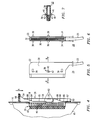
- FIG. 1 a typical subrack or shelf 2 and interface units such as line cards 4 for a switching system or other network element are shown. While specific reference is made to line cards 4, it is to be understood that the construction of the invention also can be used on trunk cards or other interface cards.
- Subrack 2 consists of side plates 5 and 6 connected by supports 8.
- a backplane 10 is connected to side plates 5 and 6 including electrical connectors 12, one connector 12 being provided for each of the line cards 4.
- Connectors 12 releasably engage connectors 14 on the line cards 4 to allow communication between the line card and the switching system or other network element.
- Line cards 4 consist of a circuit pack 15 having circuitry for controlling the lines hosted by that line card.
- a face place 16 is connected to the side of the circuit pack opposite to connector 14.
- Face plate 16 includes latches 49 on either end thereof for securing the line card to the supports 8 of frame 2 when the line cards are inserted in the frame. Face plate 16 includes an aperture 18 through which the plug 22 of cable assembly 24 can access the pin connector of the line unit. Ejection mechanism 26 is provided to disconnect plug 22 from the pin connector as will hereinafter be described.
- the line card 4 is inserted into frame 2 so that connector 14 engages the backplane connector 12 and latches 49 engage supports 8.
- Plug 22 is inserted through aperture 18 into engagement with the pin connectors, as will hereinafter be described, to complete the physical installation of the line card. It will be appreciated that while specific reference has been made to line cards 4, the physical construction of other interface units such as trunk units is identical.
- cable assembly 24 consists of a plug 22 and cable 23 where plug 22 consists of a body 30 having a plurality of receptacles 32 for receiving the pins of connector 20 of the line card 4. Each aperture 32 communicates with an electrical conductor (not shown) that connects to electrical conductors in cable 23 such that when the plug is connected to line card 4 an electrical pathway is created between the pins of connector 20 of the line card and the cable 24. Cable 24 is connected to the customer lines (not shown) as is known in the art.
- Body 30 includes at least one abutment surface 34 on either side thereof for engaging the ejection mechanism 26 as will hereinafter be described.
- a second abutment surface 36 is provided on each side of body 30 to facilitate the ejection process.
- a lug 38 is provided on each side of the body 30.
- lugs 38 include a first surface 40 that is perpendicular to the body 30 and engages the locking device and a second surface 42 that is at an angle relative to the body for camming open the locking device during insertion of the plug into the line card as will hereinafter be described. If the locking of the plug into the line card is not desired, lugs 38 can be omitted.
- pin connector 20 (FIGS. 3 and 4) consists of a plurality of pins 46 mounted in a housing 48 that is mounted to circuit pack 15 such that the pins are exposed through aperture 18 in the face plate 16. Electrical conductors connect the pins 46 to the circuitry on the circuit pack 15 as is known in the art.
- Latching mechanisms 49 are provided at either end of the face plate 16 to latch the interface card onto the subrack and securely retain the unit in the subrack. Specifically, each latching mechanism 48 pivots around pin 50 such that detents 51 engage the supports 8.
- the ejection mechanism of the invention 26 consists of a slide member 54 having a pair of identical sidewalls 56 and endwalls 58 and 60 arranged such that plug 22 can be inserted between the sidewalls into engagement with the pins 46.
- each of sidewalls 56 include flanges 62 that extend beyond and engage the backside of face plate 16.
- the flanges 62 are dimensioned such that they are trapped between pin housing 48 and the edges of aperture 18 allowing the sliding member 54 to slide along face plate but preventing the slide member from being removed from the face plate.
- This attachment design is simple and inexpensive and does not require separate fasteners thus minimizing the manufacturing cost of the line card.
- camming surfaces 64 and 66 located on the inside of each of sidewalls 56.
- Camming surfaces 64 and 66 include a relatively flat portion 65 disposed parallel to face plate 16 and an inclined portion 68 that extends away from the face plate.
- the flat portions 65 are aligned with abutment surfaces 34 and 36 of the plug such that the pins 46 can fully engage the receptacles 32.
- a flexible finger 67 extends from endwall 60 to engage the edge of aperture 18 and maintain the slide member 54 in position.
- slide member 54 moves relative to the face plate 16 in the direction of arrow A and finger 67 is deflected from engagement with the edge of aperture 18.
- inclined surfaces 68 engage abutment surfaces 34 and 36.
- the inclined surfaces 68 force plug 22 out of engagement with pins 46 in a direction perpendicular to arrow A. Because the movement of plug 30 is perpendicular to the face plate 18 and, therefore, parallel to pins 46, the pins are disengaged without being bent or otherwise damaged.
- the slide member 54 is moved in the direction opposite to arrow A to the position shown in FIG. 4 and the plug 24 is manually reinserted.
- laterally extending locking members 70 are provided along the upper edges of sidewalls 56. Locking members 70 are located so as to be aligned with lugs 38 when the slide member is in the position shown in FIG. 4. When the plug 22 is inserted into the line card, the bottom inclined surface 42 of lugs 38 engage locking members 70 and force the sidewalls 56 apart a distance large enough to allow the lugs to pass the locking members 70.
- the sidewalls 56 be constructed of a relatively flexible thermoplastic such that the sidewalls can flex outward a sufficient distance to allow passage of the plug.
- the sidewalls 56 return to the original, unflexed position such that the top flat surfaces 40 of lugs 38 are located behind locking members 70. Because the top surfaces 40 of lugs 38 are aligned behind locking members 70, these surfaces abut such that the sidewalls will not be flexed and the plug cannot be removed if a force is inadvertently applied to the plug. As a result, the plug is securely retained in the line card.
- the locking members 70 also will move relative to the plug and out of alignment with the lugs, allowing the plug to be ejected. While the use of the locking mechanism is optional, it will prevent the inadvertent disconnection of the plug, thereby preventing electrical shock resulting from inadvertent contact of a person with the exposed pins.
Landscapes
- Engineering & Computer Science (AREA)
- Signal Processing (AREA)
- Computer Networks & Wireless Communication (AREA)
- Details Of Connecting Devices For Male And Female Coupling (AREA)
- Coupling Device And Connection With Printed Circuit (AREA)
- Interface Circuits In Exchanges (AREA)
- Structure Of Telephone Exchanges (AREA)
Applications Claiming Priority (2)
| Application Number | Priority Date | Filing Date | Title |
|---|---|---|---|
| US720983 | 1996-10-15 | ||
| US08/720,983 US5889850A (en) | 1996-10-15 | 1996-10-15 | Interface card for use in a telecommunications network |
Publications (2)
| Publication Number | Publication Date |
|---|---|
| EP0837610A2 true EP0837610A2 (de) | 1998-04-22 |
| EP0837610A3 EP0837610A3 (de) | 2000-01-05 |
Family
ID=24896042
Family Applications (1)
| Application Number | Title | Priority Date | Filing Date |
|---|---|---|---|
| EP97307903A Withdrawn EP0837610A3 (de) | 1996-10-15 | 1997-10-07 | Verbesserte Schnittstellenkarte zur Verwendung in einem Telekommunikationsnetzwerk |
Country Status (5)
| Country | Link |
|---|---|
| US (1) | US5889850A (de) |
| EP (1) | EP0837610A3 (de) |
| JP (1) | JP3404262B2 (de) |
| KR (1) | KR100530429B1 (de) |
| CA (1) | CA2211469C (de) |
Families Citing this family (16)
| Publication number | Priority date | Publication date | Assignee | Title |
|---|---|---|---|---|
| AU9208198A (en) * | 1997-08-28 | 1999-03-16 | Harris Corporation | Modular digital telephone system and method including a universal telephony shelf |
| US6567518B1 (en) * | 1998-08-28 | 2003-05-20 | Teltronics, Inc. | Method of field programmable gate array configuration |
| US6317329B1 (en) * | 1998-11-13 | 2001-11-13 | Hewlett-Packard Company | Data storage module alignment system and method |
| KR100305770B1 (ko) * | 1999-10-05 | 2001-11-02 | 서평원 | 셀프보드에 유니트 삽입시 오류방지 장치 |
| US6269007B1 (en) | 1999-10-08 | 2001-07-31 | Lucent Technologies, Inc. | Apparatus and method for latching a circuit pack |
| KR100318481B1 (ko) * | 2000-02-09 | 2001-12-22 | 송문섭 | 통신기지단말기용 쉘프의 연결보드 고정 장치 |
| KR100318477B1 (ko) * | 2000-02-09 | 2001-12-24 | 송문섭 | 통신기지단말기용 쉘프의 클럭보드 고정 장치 |
| US6561836B1 (en) * | 2000-12-04 | 2003-05-13 | Cisco Technology, Inc. | System and method for coupling a communication signal to a communication device |
| US6782097B2 (en) * | 2001-08-31 | 2004-08-24 | Adc Telecommunications, Inc. | Splitter device for MDU/MTU environments |
| USD486454S1 (en) | 2001-10-19 | 2004-02-10 | Catena Networks, Inc. | Faceplate and latch for a line card |
| US7145909B2 (en) * | 2002-05-24 | 2006-12-05 | Lucent Technologies Inc. | Packet switching access platform |
| US7289516B2 (en) * | 2003-07-31 | 2007-10-30 | Lucent Technologies Inc. | Universal interface |
| US20090324243A1 (en) * | 2008-06-30 | 2009-12-31 | Lucent Technologies Inc. | Scalable load-balanced interconnect switch based on an optical switch fabric having a bank of wavelength-selective switches |
| US20090324221A1 (en) * | 2008-06-30 | 2009-12-31 | Lucent Technologies Inc. | Scalable load-balanced interconnect switch based on an arrayed waveguide grating |
| CN102738685B (zh) | 2012-06-21 | 2014-09-17 | 华为技术有限公司 | 电路板的插拔装置及服务器 |
| US9600040B1 (en) * | 2015-10-13 | 2017-03-21 | Evga Corporation | Interface card adapting device and method thereof |
Family Cites Families (14)
| Publication number | Priority date | Publication date | Assignee | Title |
|---|---|---|---|---|
| US2430011A (en) * | 1944-05-15 | 1947-11-04 | Lunceford P Gillentine | Plug ejector |
| US4579408A (en) * | 1983-04-11 | 1986-04-01 | Oki Densen Kabushiki Kaisha | Electrical connector structure with release and locking mechanism |
| DE3322856A1 (de) * | 1983-06-24 | 1985-01-03 | Siemens AG, 1000 Berlin und 8000 München | Frontsystem fuer in baugruppentraeger einschiebbare steckbaugruppen und rahmenartige baugruppentraeger zu deren aufnahme |
| JPS6253097A (ja) * | 1985-09-02 | 1987-03-07 | Toshiba Corp | 制御デ−タ伝送方式 |
| US5140501A (en) * | 1988-04-30 | 1992-08-18 | Fujitsu Limited | Mechanism for inserting and withdrawing printed board unit of electronics circuit device |
| DE4032801C2 (de) * | 1990-10-16 | 1993-10-14 | Triumph Adler Ag | Steckverbindungsanordnung zur mechanischen und elektrischen Steckverbindung von elektronischen Geräteeinheiten |
| JPH0530815U (ja) * | 1991-10-04 | 1993-04-23 | 日本電気通信システム株式会社 | 基板型コネクタ装置 |
| US5388099A (en) * | 1992-10-22 | 1995-02-07 | Digital Equipment Corporation | Backplane wiring for hub in packet data communications system |
| KR0125587Y1 (ko) * | 1992-12-30 | 1998-12-15 | 정장호 | 인쇄회로 기판의 오삽입 방지용 클립 |
| JP2513433B2 (ja) * | 1993-12-06 | 1996-07-03 | 日本電気株式会社 | プリント基板搭載用ガイドレ―ル |
| US5592475A (en) * | 1993-12-07 | 1997-01-07 | Raychem Corporation | Distributed digital loop system with trunk unit interface |
| US5480319A (en) * | 1993-12-30 | 1996-01-02 | Vlakancic; Constant G. | Electrical connector latching apparatus |
| US5468156A (en) * | 1994-09-27 | 1995-11-21 | The Whitaker Corporation | Locking system for interconnection of daughter board and mother board assemblies |
| JP2906117B2 (ja) * | 1995-01-23 | 1999-06-14 | 日本航空電子工業株式会社 | コネクタ |
-
1996
- 1996-10-15 US US08/720,983 patent/US5889850A/en not_active Expired - Lifetime
-
1997
- 1997-07-24 CA CA002211469A patent/CA2211469C/en not_active Expired - Fee Related
- 1997-09-22 JP JP25654197A patent/JP3404262B2/ja not_active Expired - Fee Related
- 1997-10-07 EP EP97307903A patent/EP0837610A3/de not_active Withdrawn
- 1997-10-10 KR KR1019970052050A patent/KR100530429B1/ko not_active Expired - Fee Related
Also Published As
| Publication number | Publication date |
|---|---|
| CA2211469C (en) | 2001-03-27 |
| JP3404262B2 (ja) | 2003-05-06 |
| CA2211469A1 (en) | 1998-04-15 |
| KR19980032734A (ko) | 1998-07-25 |
| US5889850A (en) | 1999-03-30 |
| JPH10144395A (ja) | 1998-05-29 |
| EP0837610A3 (de) | 2000-01-05 |
| KR100530429B1 (ko) | 2006-05-23 |
Similar Documents
| Publication | Publication Date | Title |
|---|---|---|
| US5889850A (en) | Interface card for use in a telecommunications network | |
| EP0487893B1 (de) | Modularer Abzweig-Steckverbinder | |
| US5074801A (en) | Modular jack patching device | |
| US6608764B2 (en) | Telecommunications patch panel | |
| US7195521B2 (en) | Front access DSX assembly | |
| CN1640155B (zh) | 电信接线板 | |
| US6345986B1 (en) | High density patching system | |
| US6053764A (en) | Patch panel and interlocking module | |
| US7121896B2 (en) | Digital switching cross-connect module | |
| US6589062B1 (en) | DSX module with removable jack | |
| CA1091796A (en) | Modular termination system for telecommunication devices | |
| US20080106881A1 (en) | Active signal cross-connect system | |
| EP1169753B1 (de) | Dsx modul mit abnehmbaren jack | |
| US5438617A (en) | Low frequency digital network cross-connect panel | |
| US5265156A (en) | Digital signal cross-connect panel | |
| US7815439B2 (en) | Insulation displacement plug-in connector and device for telecommunications and data technology | |
| CA2572768C (en) | Long frame high density patching system | |
| WO2004039095A2 (en) | Rear access dsx system | |
| GB2351854A (en) | Ditribution cable module |
Legal Events
| Date | Code | Title | Description |
|---|---|---|---|
| PUAI | Public reference made under article 153(3) epc to a published international application that has entered the european phase |
Free format text: ORIGINAL CODE: 0009012 |
|
| AK | Designated contracting states |
Kind code of ref document: A2 Designated state(s): DE FR GB |
|
| AX | Request for extension of the european patent |
Free format text: AL;LT;LV;RO;SI |
|
| PUAL | Search report despatched |
Free format text: ORIGINAL CODE: 0009013 |
|
| RIC1 | Information provided on ipc code assigned before grant |
Free format text: 6H 04Q 1/02 A, 6H 04M 3/00 B, 6H 04M 7/00 B, 6H 01R 13/633 B, 6H 01R 31/00 B, 6H 04Q 1/10 B, 6H 05K 7/14 B |
|
| AK | Designated contracting states |
Kind code of ref document: A3 Designated state(s): AT BE CH DE DK ES FI FR GB GR IE IT LI LU MC NL PT SE |
|
| AX | Request for extension of the european patent |
Free format text: AL;LT;LV;RO;SI |
|
| 17P | Request for examination filed |
Effective date: 20000626 |
|
| AKX | Designation fees paid |
Free format text: DE FR GB |
|
| 17Q | First examination report despatched |
Effective date: 20010621 |
|
| STAA | Information on the status of an ep patent application or granted ep patent |
Free format text: STATUS: THE APPLICATION IS DEEMED TO BE WITHDRAWN |
|
| 18D | Application deemed to be withdrawn |
Effective date: 20020103 |