EP0837823B1 - Saat-messmethode und vorrichtung - Google Patents
Saat-messmethode und vorrichtung Download PDFInfo
- Publication number
- EP0837823B1 EP0837823B1 EP96916823A EP96916823A EP0837823B1 EP 0837823 B1 EP0837823 B1 EP 0837823B1 EP 96916823 A EP96916823 A EP 96916823A EP 96916823 A EP96916823 A EP 96916823A EP 0837823 B1 EP0837823 B1 EP 0837823B1
- Authority
- EP
- European Patent Office
- Prior art keywords
- disc
- seeds
- discs
- metering device
- seed
- Prior art date
- Legal status (The legal status is an assumption and is not a legal conclusion. Google has not performed a legal analysis and makes no representation as to the accuracy of the status listed.)
- Revoked
Links
Images




Classifications
-
- A—HUMAN NECESSITIES
- A01—AGRICULTURE; FORESTRY; ANIMAL HUSBANDRY; HUNTING; TRAPPING; FISHING
- A01C—PLANTING; SOWING; FERTILISING
- A01C7/00—Sowing
- A01C7/04—Single-grain seeders with or without suction devices
- A01C7/042—Single-grain seeders with or without suction devices using pneumatic means
- A01C7/044—Pneumatic seed wheels
- A01C7/0445—Seed ejectors
Definitions
- This invention relates to the field of seed metering for drills and planters and, more particularly, to a metering system which is designed to work with an air seeder that separates seeds from a mobile bulk supply thereof into a plurality of separate seed streams, each containing seeds spaced at regular intervals for delivery by air conveyance streams to remote openers.
- Air seeders for metering a flow of seeds out of a bulk supply hopper and into conduits that deliver the seeds to remotely located openers are not new.
- this practice has largely been limited to seeds other than corn seeds where uniform seed spacing is critical to achieving satisfactory yield results. It is very difficult to maintain uniform spacing between individual seeds with an air seeder, especially when the seeds must be conveyed over long distances.
- the economies of scale achievable with the bulk handling and metering of corn seeds remain extremely attractive and give rise to a serious long-felt need to solve the problems heretofore experienced in the industry.
- FR-A-2291927 discloses a hollow drum having a number of peripheral grooves and apertures.
- the interior of drum is at all times exposed to suction pressure such that apertures are always experiencing suction. Consequently, seeds will remain adhered to the periphery of the drum unless they are properly stripped off by a mechanical means in the form of the extraction mechanism, which includes the extraction element for each groove.
- US-A-4,074,830 discloses a compressed air seed planter having rotating discs, each of which being subjected to air pressure that holds the seeds on the disc until the pressure is turned off at the drop zone, this arrangement does not use a single bulk seed supply chamber that is common to all of the discs. Instead, as shown best in Fig. 2, each disk has its own separate container that supplies seeds only to the one particular disc with which it is associated. Consequently, the containers are subject to frequent refilling and may or may not become empty at the same time.
- a primary object of the present invention is to fill the long-felt need in the industry for a commercially acceptable way of air-seeding corn.
- Another important object of the present invention is to provide an air seed metering and distribution system that is capable not only of accurately and reliably singulating the seeds contained in a bulk supply hopper, but also of maintaining the established spacing between the seeds as they are conveyed over fairly substantial distances to their ultimate points of insertion into the ground. It is also an important object to provide a relatively compact metering device which, notwithstanding its relative compactness, is capable of handling a large quantity of seeds.
- a metering device which can be readily expanded by the manufacturer as may be necessary or desirable to add additional runs of seed conveying hoses for additional rows of seeds to be planted.
- the seed metering device will have at its heart a bank of side-by-side metering discs arranged at the dispensing outlet of the seed hopper for receiving a supply of seeds from the hopper.
- a corner or quadrant of each disc rotates through the collection of seeds from the hopper so that cups formed around the periphery of each disc can pick up and retain one seed each as the cups sweep through the seeds.
- the hopper is pressurized and the seed cups are exhausted to the atmosphere during their seed pick up and retaining cycle so that the seeds are encouraged to hold onto the periphery of the disc once engaged by a cup.
- the cups are so shaped and dimensioned as to encourage the pick up of only one seed per cup.
- the seed cups are cut off from. the pressurized tank such that the seeds drop off the discs. At that point, they are drawn into separate transfer lines by individual venturies associated with such lines, whereupon the positive pressure air streams within the lines convey the singulated seeds to the awaiting downstream openers without disrupting the spacing achieved by the singulating action of the discs.
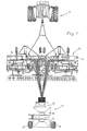
- FIG. 1 illustrates an air seeding rig of the type which may advantageously be used in connection with the present invention.
- the rig includes a towing tractor 10, a field cultivator 12 hitched to the tractor 10 and modified for planting operations, and a bulk seed cart 14 hitched to the rear of the cultivator 12.
- Most of the details of the present invention are associated with the seed cart 14 which carries mechanism for accurately separating the bulk supply of seeds into a series of individual seed streams containing seeds at regular, spaced intervals.
- the cart 14 has the ability to convey the singulated seeds of each stream to the modified field cultivator 12 where the seeds are placed in the ground by suitable openers 16 as the rig is advanced.
- a number of different types of openers 16 could be utilized in conjunction with the present invention and are well known to those skilled in the art.
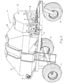
- the cart 14 has ground wheels 18, 20 and 22 that support a frame 24 above the ground.
- the frame 24, in turn, carries a large fertilizer tank 26 and a large wheat seed tank 28.
- a smaller corn seed tank 30 is supported above the frame 24 by four upright legs 32, 34, 36 and 38 (see also Figs. 3 and 4).
- the lower portion of the corn tank 30 comprises a discharge funnel 40 that hangs down into the open space between the legs 30-38 for the purpose of supplying seeds to a metering and distribution device 42 constructed in accordance with the principles of the present invention.
- the sloping rear wall 40a (Fig. 6) of the funnel 40 closes off most of the top of the metering device 42 so that a relatively small outlet 44 (Fig. 6) is presented by the funnel 40 for releasing seeds into the metering device 42.
- the sloping front wall 40b of the hopper 40 terminates at the upper extremity of the outlet 44 and merges into a short, rectangular, upright front panel 46.
- the metering device 42 includes a housing or hollow body 48 that is attached to and suspended from the funnel 40 of the corn tank 30.
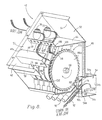
- the body 42 is partitioned into three distinct chambers, namely a relatively large, main chamber 50 in which seeds are singulated, an overhead plenum chamber 52 above the singulating chamber 50, and a lower, rear manifold chamber 54 for supplying conveying air after the seeds have been singulated into separate streams.
- a relatively large, main chamber 50 in which seeds are singulated namely a relatively large, main chamber 50 in which seeds are singulated, an overhead plenum chamber 52 above the singulating chamber 50, and a lower, rear manifold chamber 54 for supplying conveying air after the seeds have been singulated into separate streams.
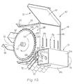
- An upright rear wall 48c of the body 48 (Figs. 6 and 10) defines the back limit of the chamber 50
- a removable access door 56 (Fig. 4) across the front of the body 48 defines the front limit of the chamber 50.
- the access door 56 is removed in Fig
- the body 48 has a pair of transverse, L-shaped channels 58 and 60 which span the side walls 48a and 48b generally at the intersection of the downwardly and forwardly sloping top of the body and the upwardly and forwardly sloping front of the body.
- the two channels 58 and 60 are spaced apart along a fore-and-aft incline by an amount corresponding to the width of the outlet 44 from the funnel 40 such that the space between the channels 58 and 60 serves as a seed inlet 62 into the singulating chamber 50. It is to be understood that the inlet 62 extends entirely across the full width of the metering body 48 from side wall 48a to side wall 48b.
- the plenum chamber 52 is generally triangular in cross-sectional configuration and has its opposite ends defined by upper portions of the two side walls 48a and 48b so that the chamber 52 extends along the full width of the singulating chamber 50.
- the rear of the plenum chamber 52 is defined by an upwardly and forwardly extending rear wall 64, while the floor of the plenum chamber 52 is defined by a horizontal partition 66 having an upturned front flange 66a.
- the front flange 66a is perforated to present a series of air inlet holes 68 corresponding in number to the number of metering discs contained within the singulating chamber 50 as will hereinafter be described.
- the plurality of holes 66 could also take the form of a single slot or other opening.
- a pair of main inlet apertures 70 and 72 are provided in the side wall 48a for supplying pressurized air from a source such as the fan 74 in Fig. 2 to the plenum chamber 52.
- the manifold chamber 54 is rectangular in cross-sectional configuration and extends across the full width of the metering body 48 at the lower rear corner thereof.
- the manifold chamber 54 has a closed top wall 54a, a closed back wall 54b, a closed bottom wall 54c and a front wall 54d that is closed except for a series of orifices 76 disposed along the length of chamber 54.
- the opposite end walls 54e and 54f have air inlets 78 and 80 respectively for connection to a source of high pressure air.
- a hose 82 from a source of high pressure air communicates with the inlet 78 of the manifold 54, while a second hose 84 from the high pressure source is coupled with the inlet 80 at the opposite end of the manifold 54.
- Another pair of hoses 86 are connected with the inlet apertures 70 and 72 to the plenum chamber 52, while at least one additional hose 88 from the high pressure source is connected with the plenum chamber 52 via an inlet aperture 90 (Fig. 4) in the side wall 48b of the plenum chamber 52.
- the orifices 76 of the manifold 54 communicate with a series of corresponding conduit fittings 92 corresponding in number to the orifices 76 and projecting downwardly and forwardly from the manifold 54.
- Each fitting 92 is coupled at its forward end with a flexible conduit 94 which extends forwardly therefrom and leads to a corresponding opener 16 on the field cultivator 12.
- a total of twelve "runs" of the conduits 94 is contemplated for delivering seeds to the front row of openers on the field cultivator 12.
- Other openers in the rows behind the front row may be conveniently utilized to put down dry fertilizer from the tank 26, or wheat seeds or the like from the tank 28.
- a plurality of additional, larger diameter hoses 96 and flat fan distributors 98 are utilized.
- Each of the fittings 92 has a restricted portion 92a through which the air flow from manifold 54 must pass in order to reach the conduit 94.
- the restriction 92a presents a venturi 100 within each fitting 92 that results in an area of negative pressure at the restricted portion 92a.
- a port 102 in the side wall of the fitting 92 at the venturi 100 communicates the fitting 92 with a seed drop inlet 104 projecting upwardly from the fitting 92 and communicating with the singulating chamber 50.
- the specific location of the seed drop inlet 104 is important with respect to receiving the metered seeds from the metering discs within the chamber 50 as will subsequently be described.
- the metering device 42 further includes a bank or stack of metering discs 106 and valve plates 108 within the singulating chamber 50.
- the discs 106 are fixed to a common mounting shaft 110 and are disposed at regularly spaced locations along the length of the latter.
- the valve plates 108 are interspersed between adjacent discs 106 and correspond in number to the discs 106.
- Each disc 106 comprises a flat circular plate of nylon material having a hexagonal mounting hole 112 in the center for matingly receiving the hexagonal mounting shaft 110. This hexagonal relationship enables the shaft 110 to impart driving rotation to the discs 106 during operation.
- Each of the discs 106 has a circumferentially extending, marginal periphery 114 that presents an outermost, radially outwardly facing, notched edge 116.
- a circumferentially extending series of seed cups 118 are formed in the edge 116 so as to present a saw tooth-like configuration for the edge 116 with the cups 118 being defined between successive pairs of teeth 120.
- Each cup 118 has an arcuately concave seat 122 extending generally the full width of the edge 116, a normally trailing rear wall 124 leading substantially radially outwardly from the seat 122 to the edge 116, and a forwardly inclined leading wall 126 extending obliquely out to the outer edge 116 at a much shallower angle than the trailing wall 124.
- the leading wall 126 is beveled on both of its opposite lateral sides to present relief bevels 128 and 130 that converge to the leading wall 126 and make it fairly thin and sharp compared to the wide seat 122.
- Each seat cup 118 has an orifice 132 in the seat 122.
- the orifice 132 is connected with a radial passage 134 leading radially inwardly toward the central axis of the disc and terminating at a transversely opening port 136 in one face 106a of the disc.
- a circular series of ports 136 is presented which circumscribes the axis of rotation of the disc 106, each individual port 136 communicating a passage 134 with an outer orifice 132 at a corresponding seed cup 118.
- the opposite face 106b of the disc 106 (Figs. 6 and 8) is smooth and flat without ports.
- Each of the upstanding valve members 108 is in the nature of a generally flat plate secured at its bottom edge 108a to the floor 48d of the metering body 48. Each plate member 108 is also secured along its rear edge 108b to the rear wall 48c of the metering body 48. Thus, the plates 108 remain stationary during rotation of the metering discs 106.
- Each of the valve plates 108 has an operating face 108c that is in opposed relationship with the face 106a of the adjacent disc 106.
- the face 108c contains structure that cooperates with the face 106a during rotation of the disc 106.
- the face 108c of each valve plate 108 has a generally kidney shaped recess 138 having a concentric peripheral wall 140 that extends from an approximate 8 o'clock position relative to the axis of a central hole 142 to an approximate 4 o'clock position.
- a diagonal non-concentric wall 144 associated with the recess 138 interconnects the wall 140 between the 8 o'clock and 4 o'clock positions thereof, such 8 o'clock and 4 o'clock positions being respectively identified by the letters "A" and "B” in Figs. 6, 11 and 12.
- a kidney shaped, resilient seal 146 associated with the outline of the recess 138 projects outwardly beyond the face 108c and into wiping engagement with the face 106a of the cooperating disc 106 (in Figs. 12 and 13, only the groove 146a for seal 146 is illustrated). As shown in Fig.
- the radius of the recess wall 140 from point A around to point B in a clockwise direction exceeds the radius of the circle of ports 136 such that the ports are in communication with the recess 138 from point A to point B.
- the ports 136 pass outside the recess 138 below the recess wall 144 and are out of communication with the recess 138.
- a circular sealing bead 148 circumscribing the hole 142 projects outwardly beyond the plane of the face 108c to maintain wiping engagement with the face 106a of the disc 106 in the vicinity of the hole 142 through the plate 108 (in Figs. 12 and 13, only the groove 148a for the bead 148 is illustrated).
- This use of the two seals 146 and 148 has the effect of sealing the recess 138 against the escape of pressurized air to the atmosphere at the operating interface between the disc 106 and the plate valve 108.
- the recess 138 has a pressurized air outlet passage 150 that opens into the passage in the vicinity of point B and leads rearwardly from that location to the back edge 108b of the plate where it defines an exhaust outlet 152 as illustrated in Fig. 11.
- the opening 154 for the outlet passage 150 is a generally rectangular opening in the side wall 146 of the recess that intersects slightly with and forms a depression in adjacent regions of the floor of the recess 138.
- the exhaust outlets 152 of the valve plates 108 are disposed in registration with corresponding exhaust outlets 156 in the rear wall 48c of the metering body.
- the mounting shaft 110 for the metering disc 106 projects outwardly through and beyond the side wall 48b of the metering body 48 as illustrated in Figs. 3 and 4. At that location, the shaft 110 carries a driven sprocket 158 that is entrained by a drive chain 160.
- the drive chain 160 is also back wrapped around the sprocket 162 of an input drive shaft 164 so that the two shafts 110 and 164 are driven in mutually opposite directions.
- a pair of idler sprockets 166 and 168 keep tension on the chain 160.
- the input drive shaft 164 has a driven sprocket 170 at its outermost end which is entrained by a chain 172 leading downwardly to a sprocket 174 (Fig. 5) on the interior surface of the cart frame 24.
- the sprocket 174 is fixed to a stub shaft 176 which also carries a larger sprocket 178.
- the larger sprocket 178 is entrained by a chain 180 which also entrains a sprocket 182 on a shaft 184.
- the shaft 176, sprocket 178, chain 180, sprocket 182 and shaft 184 comprise part of a transmission for permitting the operator to change the speed of rotation of the seed metering discs.
- the driving input power to the transmission is provided by engagement of one of the ground wheels 20 with the ground as shown in Fig. 7, whereupon such motion is transmitted forwardly to the transmission via a chain and sprocket drive assembly 186 in Fig. 7.
- the cart 14 may be utilized in such a manner as to supply corn seed alone, or both fertilizer from the tank 26 and corn seed from the tank 30.
- the second, third and fourth ranks of openers on the cultivator 12 are located between the front row of corn seed openers 16 such that fertilizer would not be placed in the same row as the corn seed, but rather on both opposite sides thereof.
- the corn tank 30 may be completely disabled and left empty while the tank 28 is utilized to meter and distribute small cereal grain seeds such as wheat, oats and barley. This gives the farmer considerable flexibility and significant efficiencies in the use of his equipment since the same equipment can be used for many different purposes with only slight modifications.
- the air seeding rig is to be utilized for corn planting, and without regard to whether or not fertilizer will also be applied, it will be understood that the seed discs 106 all rotate in unison and in a clockwise direction viewing Fig. 6, 8 and 10 as the cart 14 moves along the ground.
- Positive pressure air is directed into the plenum chamber 52 via inlets 70, 72 and 90 so as to pass through the inlet holes 68 and enter the singulating chamber 50. Consequently, the pressurized air finds its way up into the corn tank 30 through the seed inlet 62 of the metering body and the seed outlet 44 of the corn tank 30. The tank 30 is thereby pressurized.
- each disc 106 rotates through the collection of corn seeds only during a relatively small portion of its path of travel from the 6 o'clock position to approximately the 9 o'clock position, and the corn seeds tend to stay well below the axis of rotation of the discs 106.
- the cups 118 capture one seed per cup and carry the seeds upwardly out of the collection. Due to the pressurized nature of the singulating chamber 50, the orifices 132 in the seed cups 118 are admitting pressurized air during the same time that the cups are sweeping through the seeds, such that, in addition to the purely mechanical capturing of the seeds by the cups, the seeds are directed into the cups and against their seats 122 by positive air pressure.
- Each picked up seed is carried by its cup 118 around the path of travel of the disc as long as the port 136 associated with that particular seed remains within the recess 138. This is from point A to point B in Fig. 6.
- the ports 136 between point A and point B are not allowed to exhaust their air through the recess 138 and, consequently, there is no air pressure to hold the seeds in place as their cups 118 become inverted around the lower right hand portion of the path of travel of the disc. Consequently, as illustrated in Fig. 6, the seeds are released from the discs 106 at a point in the circular path of travel of the periphery of the discs corresponding approximately to point B in the recess 138.
- the singulated seeds are thus dropped from the discs 106 at regular, spaced intervals and that such spacing is maintained as they are drawn down into the primary conveying air stream within the conduits 94.
- the upper ends of the seed drop inlets 104 are positioned in close proximity to the point of release of the seeds from the discs 106 such that the opportunity for errant behavior by the released seeds is held to a minimum.
- the goal in this respect is to avoid any turbulence in the release area of the seeds, or anywhere downstream from that point, so that smooth, orderly flow of the seeds is assured and that even spacing of the seeds is maintained.
- Such maintenance of even spacing is important not only at the point of release from the metering discs 106, but at all points along the path of travel of the seeds to the openers 16, all of which is greatly enhanced by the venturi action available from the special conduit fittings 92.
- the seed metering and distribution device 42 of the present invention is especially well suited to apply air seeding technology to corn planting.
- the present invention carefully singulates each seed from the bulk supply tank and then maintains good control over that seed as it is released from its mechanical handling means and turned over to the air conveyance means.
- order, control and uniform spacing are maintained by the venturi- induced secondary air streams. The seeds never have an opportunity to linger around the seed drop inlets 104 before actually entering such structures.
- the number of "runs” of conduits 94 or rows of seeds planted can be readily adjusted by the manufacturer without appreciably increasing the space required by the metering body 48. It is only necessary to add the appropriate number of discs 106 and valve plates 108 to arrive at the final number of desired rows. Although the width of the metering body 42 may be increased to some extent, the vertical dimensions of the body will not, and the diameter of the discs likewise does not need to be increased.
- the seed cups 118 are located around the outermost edge of the disc 106, instead of being located inside of a hollow drum or the like as is disclosed in certain prior art devices, a significant number of additional seed cups or cups can be obtained for any one given diameter. Among other things, this means that, for the same diameter of metering device, more seed capacity is available such that additional seeds per acre can be planted. From an alternative perspective, the same seed capacity can be obtained with a smaller diameter disc, thus providing significant space-saving benefits.
- the unique configuration of the notched discs 106 with their aggressive "teeth" is particularly beneficial in assuring that seeds will in fact be picked up by the discs as they rotate within the singulating chamber 50.
- more than one seed per cup is discouraged because of the double beveled nature of the leading edge of each seed cup which simply eliminates surface area for a second seed to cling to.
- the rate of feeding "doubles" can be held in check.
Landscapes
- Life Sciences & Earth Sciences (AREA)
- Soil Sciences (AREA)
- Environmental Sciences (AREA)
- Sowing (AREA)
- Pretreatment Of Seeds And Plants (AREA)
Claims (17)
- Saat-Dosiervorrichtung (42) zum Trennen einer Vorratsmenge an Samen in mehrere getrennte Ströme, die jeweils Samen enthalten, die sich in regelmäßig beabstandeten Intervallen bewegen, wobei die Vorrichtung eine Aufnahmekammer (50), die angepaßt ist, um eine Zufuhr zu trennender Samen aufzunehmen und zu sammeln, eine Anzahl separater Transportleitungen (94), um die getrennten Samenströme zu enthalten und sie zum Abgabeort zu leiten, und Mittel zum Erzeugen eines Stromes von Druckluft innerhalb jeder der Leitungen (94) aufweist, um die Samen unter Beibehaltung ihrer gegenseitig beabstandeten Beziehung durch die Leitung zu transportieren, dadurch gekennzeichnet, daß die Vorrichtung zum Ausführen der Trennfunktion ferner eine Reihe nebeneinander angeordneter Dosierscheiben (106) aufweist, die für Drehungen um eine gemeinsame Achse (110) montiert sind, wobei jede der Scheiben (106) eine Rand-Peripherie (114) aufweist, die während zumindest eines Teils der kreisförmigen Bewegungsbahn der Scheibe innerhalb der Kammer (50) bewegbar ist, um die Peripherie (114) der Zufuhr von Samen in der Kammer (50) auszusetzen, wobei jede der Scheiben (106) entlang des Umfangs eine Reihe um ihre Rand-Peripherie herum beabstandet angeordneter Samenbecher (118) zum Aufnehmen und vorübergehenden Festhalten von Samen aus der Zufuhr während die Scheibe sich dreht aufweist, wobei die Vorrichtung ferner eine Struktur (108, 132, 134, 136, 138, 146, 148) zum Aufrechterhalten eines Druckes an den Samenbechern (118) während sie sich durch die Kammer bewegen und für eine Zeit danach aufweist, um Samen dadurch zu unterstützen, in ihren Bechern (118) zu bleiben bis der Druck beendet wird, wobei die Struktur ferner bedienbar ist, um den Druck an einem bestimmten Punkt in der Bewegungsbahn jedes Bechers zu beenden, um dadurch zu bewirken, daß die Samen jeder Scheibe in regelmäßigen Abständen aus ihren Bechern (118) in ihre jeweiligen Leitungen (94) fallen.
- Saat-Dosiervorrichtung nach Anspruch 1, dadurch gekennzeichnet, daß die Struktur zum Aufrechterhalten und Beenden eines Druckes an den Samenbechern Durchgangseinrichtungen (134, 136) in jeder Scheibe umfaßt, die mit den Bechern (118) in Verbindung stehen, wobei die Scheiben (106) entlang der Achse (110) voneinander beabstandet sind und die Struktur ferner eine Reihe stationärer, voneinander beabstandeter Steuerbauteile (108) umfaßt, die wechselweise zwischen den Scheiben (106) angeordnet sind und Bereiche (138, 146, 148) aufweisen, die angeordnet sind, um während der Drehung der Scheiben mit den Durchgangseinrichtungen einer unmittelbar benachbarten Scheibe zusammenzuwirken, um das Aufrechterhalten und Beenden des Druckes zu bewirken.
- Saat-Dosiervorrichtung nach Anspruch 2, dadurch gekennzeichnet, daß jedes Bauteil (108) und eine unmittelbar benachbarte Scheibe einander gegenüberliegende, entgegengesetzt gerichtete Flächen (106c, 108a) aufweisen, wobei der Bereich des Bauteils (108), der mit den Durchgangseinrichtungen (134, 136) der Scheibe zusammenwirkt, eine Ausnehmung (138) in der Fläche (108a) der Scheibe umfaßt, die mit einem Luftauslaß (156) in Verbindung steht, wobei die Durchgangseinrichtungen in der Scheibe eine kreisförmige Reihe von Öffnungen (136) aufweisen, die um die Drehachse herum angeordnet sind und mit entsprechenden Bechern (118) in Verbindung stehen, wobei die Ausnehmung (138) und die Öffnungen (136) so angeordnet sind, daß jede aufeinanderfolgende Öffnung verbunden, in Verbindung gehalten und anschließend von dem Auslaß (156) getrennt wird, während die Scheibe sich entlang ihrer Bewegungsbahn dreht.
- Saat-Dosiervorrichtung nach Anspruch 3, dadurch gekennzeichnet, daß jedes Bauteil (108) ein Dichtungselement (146) aufweist, das die Ausnehmung (138) umschreibt und während der Drehung der Scheibe in wischender Anlage an die Fläche (106a) der unmittelbar benachbarten Scheibe angeordnet ist, um ein Entweichen von Luft zu verhindern.
- Saat-Dosiervorrichtung nach Anspruch 4, dadurch gekennzeichnet, daß jedes Bauteil ferner durch es hindurch ein Loch (142) zum drehbaren Aufnehmen einer Antriebswelle für die Scheiben (106) aufweist, wobei das Loch innerhalb der Ausnehmung (138) angeordnet ist und jedes Bauteil ferner eine Dichtungswulst (148) aufweist, die das Loch (142) umschreibt und zur wischenden Anlage an die Fläche der unmittelbar benachbarten Scheibe während der Drehung der Scheibe angeordnet ist, um während der Drehung der Scheibe innerhalb der Ausnehmung (138) und zwischen dem Element (146) und der Wulst (148) eine Druckkammer (50) zu bilden.
- Saat-Dosiervorrichtung nach Anspruch 5, dadurch gekennzeichnet, daß die Ausnehmung (138) jedes Bauteils einen Boden aufweist, wobei der Boden eine Öffnung (132) hat, die mit dem Auslaß (156) in Verbindung steht.
- Saat-Dosiervorrichtung nach Anspruch 3, dadurch gekennzeichnet, daß die Transportleitungen (94) mit einer Venturianordnung (100) zum Erzeugen eines induzierten sekundären Luftstromes ausgestattet sind, um die Samen in die Leitungen (94) zu saugen, wenn sie von den Scheiben (106) fallengelassen werden.
- Saat-Dosiervorrichtung nach Anspruch 7, dadurch gekennzeichnet, daß die Venturianordnung (100) für jede Leitung einen separaten Lufttrichter aufweist, wobei jede der Leitungen (94) einen Einlaß (104) hat, der angeordnet ist, um Samen zu empfangen, die von der Scheibe für diese Leitung freigegeben wurden, und um die Samen in den Luftstrom innerhalb der Leitung zu leiten.
- Saat-Dosiervorrichtung nach Anspruch 1, dadurch gekennzeichnet, daß die Transportleitungen (94) mit einer Venturianordnung (100) zum Erzeugen eines induzierten sekundären Luftstromes ausgestattet sind, um die Samen in die Leitungen (94) zu saugen, wenn sie von den Scheiben (106) fallengelassen werden.
- Saat-Dosiervorrichtung nach Anspruch 9, dadurch gekennzeichnet, daß die Venturianordnung für jede Leitung einen separaten Lufttrichter aufweist, wobei jede der Leitungen (94) einen Einlaß (104) hat, der angeordnet ist, um Samen zu empfangen, die für diese Leitung von der Scheibe fallen, und um die Samen in den Luftstrom innerhalb der Leitung zu leiten.
- Saat-Dosiervorrichtung nach Anspruch 1, dadurch gekennzeichnet, daß jede der Scheiben (106) einen radial nach außen gerichteten Rand (116) an ihrer Rand-Peripherie (114) aufweist, wobei die Becher (118) in dem Rand (116) angeordnet sind.
- Saat-Dosiervorrichtung nach Anspruch 11, dadurch gekennzeichnet, daß jeder der Becher (118) in dem Rand (116) eine sich radial nach außen öffnende Aussparung mit einem konkaven Sitz (122) umfaßt, wobei der Sitz (122) darin eine Öffnung (132) hat, die einen Teil der Struktur zum Aufrechterhalten von Druck an den Samenbechern (118) umfaßt.
- Saat-Dosiervorrichtung nach Anspruch 12, dadurch gekennzeichnet, daß jede Aussparung ferner eine normalerweise voreilende vordere Flanke (126), die sich von dem äußersten Rand (116) nach innen zur Vorderseite des Sitzes (122) erstreckt, und eine normalerweise nacheilende hintere Flanke (124) aufweist, die sich von dem äußersten Rand (116) zur Rückseite des Sitzes (122) erstreckt, wobei die vordere Flanke (126) der Aussparung in einem allmählicheren Winkel in Richtung des Sitzes (122) verläuft als die hintere Flanke (124).
- Saat-Dosiervorrichtung nach Anspruch 13, dadurch gekennzeichnet, daß die vordere Flanke (126) jeder Aussparung ein Paar gegenüberliegend angeordneter, zusammenlaufender Oberflächen (128, 130) aufweist, die bewirken, daß die vordere Flanke (126) der Aussparung dünner ist als der Sitz (122) und die hintere Flanke (124) der Aussparung.
- Saat-Dosiervorrichtung nach Anspruch 14, dadurch gekennzeichnet, daß die vordere Flanke (126) jeder Aussparung den äußeren Rand (116) der Scheibe in einem kurzen Umfangsabstand von dem Schnittpunkt der hinteren Flanke (124) der nächsten folgenden Aussparung mit dem äußeren Rand (116) der Scheibe schneidet, um dadurch entlang des Umfangs eine Reihe radial nach außen vorstehender Zähne (120) um die Scheibe herum darzustellen, wobei die Aussparungen zwischen direkt benachbarten Zähnen (120) angeordnet sind.
- Saat-Dosiervorrichtung nach Anspruch 15, dadurch gekennzeichnet, daß die Struktur zum Aufrechterhalten und Beenden eines Druckes an den Samenbechern (118) Durchgangseinrichtungen (134, 136) in jeder Scheibe umfaßt, die mit den Öffnungen (132) in den Bechern (118) in Verbindung stehen, wobei die Scheiben (106) entlang der Achse voneinander beabstandet sind und die Struktur ferner eine Reihe stationärer, voneinander beabstandeter Steuerbauteile (108) umfaßt, die wechselweise zwischen den Scheiben (106) angeordnet sind und Bereiche (138, 146, 148) aufweisen, die angeordnet sind, um während der Drehung der Scheiben mit den Durchgangseinrichtungen einer unmittelbar benachbarten Scheibe zusammenzuwirken, um das Aufrechterhalten und Beenden des Druckes zu bewirken.
- Saat-Dosiervorrichtung nach Anspruch 16, dadurch gekennzeichnet, daß jedes Bauteil (108) und eine unmittelbar benachbarte Scheibe einander gegenüberliegende, entgegengesetzt gerichtete Flächen (106c, 108a) aufweisen, wobei der Bereich des Bauteils (108), der mit den Durchgangseinrichtungen (134, 136) der Scheibe zusammenwirkt, eine Ausnehmung (138) in der Fläche (108a) der Scheibe umfaßt, die mit einem Auslaß (156) in Verbindung steht, wobei die Durchgangseinrichtungen in der Scheibe eine kreisförmige Reihe von Öffnungen (136) aufweisen, die um die Drehachse herum angeordnet sind und mit ensprechenden Öffnungen (132) in Verbindung stehen, wobei die Ausnehmung (138) und die Öffnungen (136) so angeordnet sind, daß jede aufeinanderfolgende Öffnung verbunden, in Verbindung gehalten und anschließend von dem Auslaß (156) getrennt wird, während die Scheibe sich entlang ihrer Bewegungsbahn dreht.
Applications Claiming Priority (3)
| Application Number | Priority Date | Filing Date | Title |
|---|---|---|---|
| US500193 | 1995-07-10 | ||
| US08/500,193 US5601209A (en) | 1995-07-10 | 1995-07-10 | Seed metering apparatus |
| PCT/US1996/008102 WO1997003007A1 (en) | 1995-07-10 | 1996-05-31 | Seed metering method and apparatus |
Publications (3)
| Publication Number | Publication Date |
|---|---|
| EP0837823A1 EP0837823A1 (de) | 1998-04-29 |
| EP0837823A4 EP0837823A4 (de) | 1998-10-28 |
| EP0837823B1 true EP0837823B1 (de) | 2002-08-28 |
Family
ID=23988421
Family Applications (1)
| Application Number | Title | Priority Date | Filing Date |
|---|---|---|---|
| EP96916823A Revoked EP0837823B1 (de) | 1995-07-10 | 1996-05-31 | Saat-messmethode und vorrichtung |
Country Status (7)
| Country | Link |
|---|---|
| US (1) | US5601209A (de) |
| EP (1) | EP0837823B1 (de) |
| AU (1) | AU715442B2 (de) |
| BR (1) | BR9609632A (de) |
| CA (1) | CA2226086A1 (de) |
| DE (1) | DE69623295T2 (de) |
| WO (1) | WO1997003007A1 (de) |
Cited By (1)
| Publication number | Priority date | Publication date | Assignee | Title |
|---|---|---|---|---|
| WO2014173261A1 (zh) * | 2013-04-21 | 2014-10-30 | Liu Baocai | 气力式播种排种系统 |
Families Citing this family (48)
| Publication number | Priority date | Publication date | Assignee | Title |
|---|---|---|---|---|
| US6109193A (en) * | 1995-12-29 | 2000-08-29 | Case Corporation | Seed planter apparatus and method |
| US6564730B2 (en) | 1995-12-29 | 2003-05-20 | Case Corporation | Seed planter apparatus and method |
| US5915312A (en) * | 1997-08-29 | 1999-06-29 | Case Corporation | Pneumatic seed delivery system |
| US6044779A (en) * | 1998-04-15 | 2000-04-04 | Case Corporation | Multiple drop seed disc |
| US6145455A (en) * | 1999-03-17 | 2000-11-14 | Case Corporation | Agricultural material metering system |
| US6213690B1 (en) * | 1999-03-30 | 2001-04-10 | Deere & Company | Distribution manifold for air seeder |
| US6320183B1 (en) * | 1999-06-28 | 2001-11-20 | Deere & Company | Product sensors for air seeder |
| US6668738B2 (en) * | 2002-03-21 | 2003-12-30 | Case, Llc | Bulk fill delivery venturi system |
| US6935254B2 (en) * | 2002-08-08 | 2005-08-30 | Deere & Company | Split seed hoppers for seed on demand seeding machine |
| US7174839B2 (en) * | 2004-08-17 | 2007-02-13 | Ben Tun Hsin Tseng | Seed planting system for multiple types of crops |
| US7775169B2 (en) * | 2006-05-03 | 2010-08-17 | Cnh America Llc | Access assembly between adjacent product storage tanks on a planting implement |
| US7469915B2 (en) * | 2006-05-03 | 2008-12-30 | Cnh America, Llc | Access assembly to adjacent product storage tanks on a planting implement |
| US20080053353A1 (en) * | 2006-09-01 | 2008-03-06 | Norbert Werner | Four box seed box mount with rotary platform and unloading conveyor |
| DE102008037397A1 (de) * | 2008-09-26 | 2010-04-01 | Horsch Maschinen Gmbh | Einzelkorndosiervorrichtung |
| US8850995B2 (en) | 2009-02-02 | 2014-10-07 | Deere & Company | Seeding machine with seed delivery system |
| US8671856B2 (en) | 2009-02-02 | 2014-03-18 | Deere & Company | Planting unit for a seeding machine having blocking member to control hand-off of seed from a seed meter to a seed delivery system |
| US8001914B2 (en) * | 2009-06-12 | 2011-08-23 | Great Plains Manufacturing, Inc. | Air-assisted planting system having a single fan with pressure-responsive splitting of air streams for conveying and metering functions |
| US8061281B1 (en) | 2009-09-14 | 2011-11-22 | Drouhard Rex B | Garden seeder |
| US20110155030A1 (en) * | 2009-12-28 | 2011-06-30 | Pioneer Hi-Bred International, Inc. | System and method for planting seed using a multi-way seed sample splitter |
| CA2719827A1 (en) * | 2010-11-03 | 2012-05-03 | Straw Track Manufacturing Inc. | Air seeder tank and distribution apparatus |
| US8601963B2 (en) * | 2011-01-06 | 2013-12-10 | Cnh Canada, Ltd. | Seed metering assembly having modular and independently controlled metering units |
| DE102011001143A1 (de) * | 2011-03-08 | 2012-09-13 | Amazonen-Werke H. Dreyer Gmbh & Co. Kg | Pneumatische Einzelkornsämaschine |
| US8671857B2 (en) | 2011-03-10 | 2014-03-18 | Cnh Canada, Ltd. | Variable geometry meter roller |
| US8850998B2 (en) | 2011-03-25 | 2014-10-07 | Deere & Company | Planting unit for a seeding machine having a seed meter and seed delivery system |
| US10123524B2 (en) | 2014-06-19 | 2018-11-13 | Cnh Industrial Canada, Ltd. | Active system for optimization and plugging avoidance of seed/fertilizer in transport conducts |
| US9526201B2 (en) | 2015-01-05 | 2016-12-27 | Cnh Industrial America Llc | Twin-row planter with tandem driven seed meters |
| USD816726S1 (en) | 2017-03-09 | 2018-05-01 | Cnh Industrial Canada, Ltd. | Meter roller for an agricultural metering system |
| US10405485B2 (en) | 2017-03-09 | 2019-09-10 | Cnh Industrial Canada, Ltd. | Meter roller for an agricultural metering system |
| US10149429B2 (en) | 2017-03-09 | 2018-12-11 | Cnh Industrial Canada, Ltd. | Meter roller for an agricultural metering system |
| US10085376B1 (en) | 2017-03-09 | 2018-10-02 | Cnh Industrial Canada, Ltd. | Meter roller for an agricultural metering system |
| US10292324B2 (en) | 2017-03-10 | 2019-05-21 | Cnh Industrial Canada, Ltd. | Meter roller for an agricultural metering system |
| USD815156S1 (en) | 2017-03-10 | 2018-04-10 | Cnh Industrial Canada, Ltd. | Meter roller for an agricultural metering system |
| USD815157S1 (en) | 2017-03-10 | 2018-04-10 | Cnh Industrial Canada, Ltd. | Meter roller for an agricultural metering system |
| US10390479B2 (en) | 2017-03-14 | 2019-08-27 | Cnh Industrial Canada, Ltd. | Flow control insert for an agricultural metering system |
| US10362727B2 (en) | 2017-03-14 | 2019-07-30 | Cnh Industrial Canada, Ltd. | Flow control insert for an agricultural metering system |
| WO2019070820A1 (en) | 2017-10-03 | 2019-04-11 | Ag Leader Technology | APPARATUS FOR MEASURING CONTROLLED AIR PULSES FOR AGRICULTURAL PLANTERS AND ASSOCIATED SYSTEMS AND METHODS |
| US11277961B2 (en) | 2018-02-09 | 2022-03-22 | Ag Leader Technology | Seed spacing device for an agricultural planter and related systems and methods |
| CN110622659A (zh) * | 2018-06-21 | 2019-12-31 | 南京农业大学 | 一种种盘与负压气室同步转动的气型组合式排种器 |
| US11523554B2 (en) | 2019-01-25 | 2022-12-13 | Ag Leader Technology | Dual seed meter and related systems and methods |
| AU2020268428B2 (en) | 2019-05-08 | 2025-08-14 | Precision Planting Llc | Seed orientation system for agricultural planters |
| US12419213B2 (en) | 2019-05-08 | 2025-09-23 | Precision Planting Llc | Aerodynamic and centrifugal seed orientation system for agricultural planters |
| US11785881B2 (en) | 2019-08-19 | 2023-10-17 | Ag Leader Technology | Adjustable seed meter and related systems and methods |
| US11877530B2 (en) | 2019-10-01 | 2024-01-23 | Ag Leader Technology | Agricultural vacuum and electrical generator devices, systems, and methods |
| US11770996B2 (en) | 2020-02-03 | 2023-10-03 | Cnh Industrial America Llc | Housing for a modular meter assembly of a dry product applicator |
| WO2023007284A1 (en) | 2021-07-28 | 2023-02-02 | Precision Planting Llc | Aerodynamic and centrifugal seed orientation system for agricultural planters |
| WO2023062507A2 (en) | 2021-10-11 | 2023-04-20 | Precision Planting Llc | Seed receiver and path constrainer for an agricultural planter seed orientation system |
| CA3227542A1 (en) * | 2021-10-11 | 2023-04-20 | Precision Planting Llc | Seed accelerator |
| USD1111054S1 (en) | 2023-05-27 | 2026-02-03 | Torq-Masters Industries, Inc. | Locker set for a differential |
Family Cites Families (16)
| Publication number | Priority date | Publication date | Assignee | Title |
|---|---|---|---|---|
| US3048132A (en) * | 1959-10-12 | 1962-08-07 | John F Morgan | Seed pellet dispenser and planter |
| NL6407284A (de) * | 1964-06-26 | 1965-12-27 | ||
| FR1503687A (fr) * | 1966-10-10 | 1967-12-01 | Semoir | |
| US4074830A (en) * | 1974-09-23 | 1978-02-21 | Allis-Chalmers Corporation | Compressed air seed planter |
| US4047638A (en) * | 1974-10-02 | 1977-09-13 | Allis-Chalmers Corporation | Seed disc for an air planter |
| US4026437A (en) * | 1974-11-22 | 1977-05-31 | Cambridge Consultants Ltd. | Seed drill |
| US4037755A (en) * | 1976-01-29 | 1977-07-26 | Massey-Ferguson Inc. | Pneumatic seed dispensing apparatus |
| US4094444A (en) * | 1977-03-18 | 1978-06-13 | Stanhay (Ashford) Limited | Seed metering device having high friction material on rotating wheel |
| JPS5554714Y2 (de) * | 1978-01-11 | 1980-12-17 | ||
| US4306509A (en) * | 1979-03-08 | 1981-12-22 | North Carolina State University At Raleigh | Vacuum drum planter |
| US4241849A (en) * | 1979-05-07 | 1980-12-30 | Allis-Chalmers Corporation | Air cut-off pad for an air planter with seed discharge feature |
| US4496075A (en) * | 1980-08-14 | 1985-01-29 | Ray Frank L | Rotary metering and dispensing apparatus |
| SE424801B (sv) * | 1980-12-19 | 1982-08-16 | Andersson Alf Ingf Hb | Anordning for radsadd av fron med forutbestemda inbordes mellanrum |
| US4519525A (en) * | 1981-06-01 | 1985-05-28 | J. I. Case Company | Seed dispenser for planters |
| CA1149235A (en) * | 1982-01-29 | 1983-07-05 | Cecil B. Machnee | Dispensing wheel and shaft mounting arrangement therefor |
| US5170909A (en) * | 1983-10-31 | 1992-12-15 | Deere & Company | Vacuum seed meter |
-
1995
- 1995-07-10 US US08/500,193 patent/US5601209A/en not_active Expired - Fee Related
-
1996
- 1996-05-31 EP EP96916823A patent/EP0837823B1/de not_active Revoked
- 1996-05-31 BR BR9609632-2A patent/BR9609632A/pt not_active IP Right Cessation
- 1996-05-31 DE DE69623295T patent/DE69623295T2/de not_active Expired - Fee Related
- 1996-05-31 AU AU59570/96A patent/AU715442B2/en not_active Ceased
- 1996-05-31 CA CA002226086A patent/CA2226086A1/en not_active Abandoned
- 1996-05-31 WO PCT/US1996/008102 patent/WO1997003007A1/en not_active Ceased
Cited By (1)
| Publication number | Priority date | Publication date | Assignee | Title |
|---|---|---|---|---|
| WO2014173261A1 (zh) * | 2013-04-21 | 2014-10-30 | Liu Baocai | 气力式播种排种系统 |
Also Published As
| Publication number | Publication date |
|---|---|
| US5601209A (en) | 1997-02-11 |
| WO1997003007A1 (en) | 1997-01-30 |
| CA2226086A1 (en) | 1997-01-30 |
| BR9609632A (pt) | 1999-12-21 |
| EP0837823A1 (de) | 1998-04-29 |
| DE69623295D1 (de) | 2002-10-02 |
| EP0837823A4 (de) | 1998-10-28 |
| AU5957096A (en) | 1997-02-10 |
| AU715442B2 (en) | 2000-02-03 |
| DE69623295T2 (de) | 2003-01-02 |
Similar Documents
| Publication | Publication Date | Title |
|---|---|---|
| AU715442B2 (en) | Seed metering apparatus | |
| US11849665B2 (en) | Seeding machine with seed delivery system | |
| US11357164B2 (en) | Multiple variety seed meter of a planter for planting multiple seed varieties | |
| US6308646B1 (en) | Tuning orifice for pneumatic metering manifold | |
| US10368478B2 (en) | Multiple variety seed meter with segmented sump arrangement and seed switching arrangement | |
| US10575456B2 (en) | Purging system for multiple variety seed meter | |
| US6237514B1 (en) | Belted seed metering device | |
| EP2145519B1 (de) | Pneumatische Sähmaschine | |
| RU2538387C2 (ru) | Устройство для рециркуляции воздуха в сельскохозяйственной машине | |
| US6142086A (en) | Air seeder singulation system | |
| US6899042B1 (en) | Cleanup system for a planting implement | |
| EP3136834A1 (de) | Duale mais- und sojabohnensaatscheibe | |
| US20160338261A1 (en) | Universal seed metering disc |
Legal Events
| Date | Code | Title | Description |
|---|---|---|---|
| PUAI | Public reference made under article 153(3) epc to a published international application that has entered the european phase |
Free format text: ORIGINAL CODE: 0009012 |
|
| 17P | Request for examination filed |
Effective date: 19980115 |
|
| AK | Designated contracting states |
Kind code of ref document: A1 Designated state(s): DE FR GB |
|
| A4 | Supplementary search report drawn up and despatched |
Effective date: 19980909 |
|
| AK | Designated contracting states |
Kind code of ref document: A4 Designated state(s): DE FR GB |
|
| 17Q | First examination report despatched |
Effective date: 20010112 |
|
| GRAG | Despatch of communication of intention to grant |
Free format text: ORIGINAL CODE: EPIDOS AGRA |
|
| GRAG | Despatch of communication of intention to grant |
Free format text: ORIGINAL CODE: EPIDOS AGRA |
|
| GRAH | Despatch of communication of intention to grant a patent |
Free format text: ORIGINAL CODE: EPIDOS IGRA |
|
| GRAH | Despatch of communication of intention to grant a patent |
Free format text: ORIGINAL CODE: EPIDOS IGRA |
|
| GRAA | (expected) grant |
Free format text: ORIGINAL CODE: 0009210 |
|
| AK | Designated contracting states |
Kind code of ref document: B1 Designated state(s): DE FR GB |
|
| REG | Reference to a national code |
Ref country code: GB Ref legal event code: FG4D |
|
| REF | Corresponds to: |
Ref document number: 69623295 Country of ref document: DE Date of ref document: 20021002 |
|
| ET | Fr: translation filed | ||
| PGFP | Annual fee paid to national office [announced via postgrant information from national office to epo] |
Ref country code: FR Payment date: 20030508 Year of fee payment: 8 |
|
| PGFP | Annual fee paid to national office [announced via postgrant information from national office to epo] |
Ref country code: GB Payment date: 20030528 Year of fee payment: 8 |
|
| PLBI | Opposition filed |
Free format text: ORIGINAL CODE: 0009260 |
|
| PGFP | Annual fee paid to national office [announced via postgrant information from national office to epo] |
Ref country code: DE Payment date: 20030612 Year of fee payment: 8 |
|
| PLAX | Notice of opposition and request to file observation + time limit sent |
Free format text: ORIGINAL CODE: EPIDOSNOBS2 |
|
| 26 | Opposition filed |
Opponent name: AMAZONEN-WERKEH. DREYER GMBH & CO. KG Effective date: 20030528 |
|
| PLAX | Notice of opposition and request to file observation + time limit sent |
Free format text: ORIGINAL CODE: EPIDOSNOBS2 |
|
| PLAX | Notice of opposition and request to file observation + time limit sent |
Free format text: ORIGINAL CODE: EPIDOSNOBS2 |
|
| PLAX | Notice of opposition and request to file observation + time limit sent |
Free format text: ORIGINAL CODE: EPIDOSNOBS2 |
|
| PG25 | Lapsed in a contracting state [announced via postgrant information from national office to epo] |
Ref country code: GB Free format text: LAPSE BECAUSE OF NON-PAYMENT OF DUE FEES Effective date: 20040531 |
|
| PG25 | Lapsed in a contracting state [announced via postgrant information from national office to epo] |
Ref country code: DE Free format text: LAPSE BECAUSE OF NON-PAYMENT OF DUE FEES Effective date: 20041201 |
|
| GBPC | Gb: european patent ceased through non-payment of renewal fee | ||
| PG25 | Lapsed in a contracting state [announced via postgrant information from national office to epo] |
Ref country code: FR Free format text: LAPSE BECAUSE OF NON-PAYMENT OF DUE FEES Effective date: 20050131 |
|
| REG | Reference to a national code |
Ref country code: FR Ref legal event code: ST |
|
| RDAF | Communication despatched that patent is revoked |
Free format text: ORIGINAL CODE: EPIDOSNREV1 |
|
| RDAG | Patent revoked |
Free format text: ORIGINAL CODE: 0009271 |
|
| STAA | Information on the status of an ep patent application or granted ep patent |
Free format text: STATUS: PATENT REVOKED |
|
| 27W | Patent revoked |
Effective date: 20050428 |