EP0838079B1 - Schutzschalter mit anschlussmutterhaltervorrichtung - Google Patents
Schutzschalter mit anschlussmutterhaltervorrichtung Download PDFInfo
- Publication number
- EP0838079B1 EP0838079B1 EP97924663A EP97924663A EP0838079B1 EP 0838079 B1 EP0838079 B1 EP 0838079B1 EP 97924663 A EP97924663 A EP 97924663A EP 97924663 A EP97924663 A EP 97924663A EP 0838079 B1 EP0838079 B1 EP 0838079B1
- Authority
- EP
- European Patent Office
- Prior art keywords
- terminal
- nut
- circuit breaker
- casing
- retainer
- Prior art date
- Legal status (The legal status is an assumption and is not a legal conclusion. Google has not performed a legal analysis and makes no representation as to the accuracy of the status listed.)
- Expired - Lifetime
Links
- 238000000034 method Methods 0.000 claims description 2
- 238000000465 moulding Methods 0.000 claims description 2
- 230000000717 retained effect Effects 0.000 description 4
- 238000003780 insertion Methods 0.000 description 3
- 230000037431 insertion Effects 0.000 description 3
- 230000005611 electricity Effects 0.000 description 2
- 238000009413 insulation Methods 0.000 description 2
- 230000007246 mechanism Effects 0.000 description 2
- 238000012986 modification Methods 0.000 description 2
- 230000004048 modification Effects 0.000 description 2
- 238000005728 strengthening Methods 0.000 description 2
- 238000010276 construction Methods 0.000 description 1
- 239000000463 material Substances 0.000 description 1
- 230000013011 mating Effects 0.000 description 1
- 239000012811 non-conductive material Substances 0.000 description 1
- 239000004033 plastic Substances 0.000 description 1
- 239000002985 plastic film Substances 0.000 description 1
- 239000012815 thermoplastic material Substances 0.000 description 1
- 230000007704 transition Effects 0.000 description 1
Images





Classifications
-
- H—ELECTRICITY
- H01—ELECTRIC ELEMENTS
- H01H—ELECTRIC SWITCHES; RELAYS; SELECTORS; EMERGENCY PROTECTIVE DEVICES
- H01H71/00—Details of the protective switches or relays covered by groups H01H73/00 - H01H83/00
- H01H71/08—Terminals; Connections
-
- H—ELECTRICITY
- H01—ELECTRIC ELEMENTS
- H01R—ELECTRICALLY-CONDUCTIVE CONNECTIONS; STRUCTURAL ASSOCIATIONS OF A PLURALITY OF MUTUALLY-INSULATED ELECTRICAL CONNECTING ELEMENTS; COUPLING DEVICES; CURRENT COLLECTORS
- H01R4/00—Electrically-conductive connections between two or more conductive members in direct contact, i.e. touching one another; Means for effecting or maintaining such contact; Electrically-conductive connections having two or more spaced connecting locations for conductors and using contact members penetrating insulation
- H01R4/28—Clamped connections, spring connections
- H01R4/30—Clamped connections, spring connections utilising a screw or nut clamping member
- H01R4/305—Clamped connections, spring connections utilising a screw or nut clamping member having means for facilitating engagement of conductive member or for holding it in position
-
- H—ELECTRICITY
- H01—ELECTRIC ELEMENTS
- H01H—ELECTRIC SWITCHES; RELAYS; SELECTORS; EMERGENCY PROTECTIVE DEVICES
- H01H1/00—Contacts
- H01H1/58—Electric connections to or between contacts; Terminals
- H01H1/5855—Electric connections to or between contacts; Terminals characterised by the use of a wire clamping screw or nut
-
- H—ELECTRICITY
- H01—ELECTRIC ELEMENTS
- H01H—ELECTRIC SWITCHES; RELAYS; SELECTORS; EMERGENCY PROTECTIVE DEVICES
- H01H71/00—Details of the protective switches or relays covered by groups H01H73/00 - H01H83/00
- H01H71/02—Housings; Casings; Bases; Mountings
- H01H71/0207—Mounting or assembling the different parts of the circuit breaker
- H01H2071/0242—Assembling parts of a circuit breaker by using snap mounting techniques
Definitions
- This invention relates generally to electric circuit breakers according to the preamble of claim 1. (GB-A-2078012).
- Circuit breakers are commonly used for temporary interruption of electrical power to electrical devices or loads.
- Various circuit breaker mechanisms have evolved and have been perfected over time on the basis of application-specific factors such as current capacity, response time, and the type of reset (manual or remote) function desired of the circuit breaker.
- circuit breaker mechanism employs a thermo-magnetic tripping device to trip a latch in response to a specific range of over-current conditions.
- a double-break circuit breaker two sets of current breaking contacts are included to accommodate a higher level of over-current conditions than can be handled by one set of contacts.
- the electro-mechanical assembly that is typical of those used in circuit breakers of the present invention has been described before. For this reason United States Patent No. 5,430,419 is incorporated herein by reference in its entirety.
- a circuit breaker typically has two terminals, one for connection to a power source and one for connection to the load. Connection of these terminals places the circuit breaker within the circuit between the source and the load. These connections may be assembled in a factory or in the field. In either case it is preferable to simplify the assembly.
- the terminal connecting to a source is typically connected to a bus bar, while the terminal connecting to the load may be connected to a crimp lug or some other type of connector.
- a circuit breaker terminal can be connected to its source or load by various means including bolts, screws, and friction fits or snap-ons.
- a rod-shaped connector such as a bolt or screw
- a receiving or tightening device such as a nut, is attached to the rod-shaped connector for making up and tightening the connection between the terminal and the source or load.
- a plastic insulating sheet has been used in the past to provide a dielectric between energized parts and a grounded panel. The plastic sheet allows compact construction of a circuit breaker and panelboard assembly.
- a device that holds the nut in place for later assembly of the terminal to a connector would be desirable. It would also be desirable for the device to provide insulation between the screw and/or nut and the grounded surface.
- US-A-4,676,706 describes a clip nut for securing together a plurality of workpieces with a bolt and a nut.
- the clip nut comprises a generally U-shaped body formed of two portions connected by a hinge. On one of the portions a nut retaining section is provided in one of the portions of the body to retain a nut whilst a panel is held between the two portions and a screw is inserted through the panel and screwed into the nut.
- GB-A-2 078 012 describes an electrical changeover switch comprising a body having a plurality of contacts which are located in a groove in the body. The other end of the contacts remote from the portion located in the groove have an aperture to receive a screw which is threaded into a nut retained within a recess in the body of the switch.
- a circuit breaker for interrupting power in a circuit path between a source and a load, comprising an electro-mechanical assembly including first and second contacts co-operatively arranged in the circuit path for providing current from the source to the load, wherein at least one of the contacts is moveable for interrupting the power provided to the load; a terminal connected to the first contact; a casing for enclosing the electro-mechanical assembly; characterised by a terminal nut retainer engaged with the casing proximate to the terminal, the terminal nut retainer having a body and a cavity in the body for holding a nut and wherein having a tenon and a mortise adjacent the tenon for sliding engagement with the casing and a projection for locking engagement with the casing.
- Another aspect of the invention provides a method for holding a nut close to a terminal, comprising placing the terminal in a casing having opposing grooves and opposing slots below the terminal; moulding a terminal nut retainer comprising a body having a cavity for holding the nut, and opposing sides, wherein the sides have projections for sliding engagement with the grooves and locking projections for locking engagement with the slots; placing the nut in the cavity and inserting the terminal nut retaining into the casing, wherein the projections slideably engage the grooves and the locking projections lock into the slots.
- FIG. 1 shows an perspective view of a terminal nut retainer 10.
- the terminal nut retainer 10 is preferably made using a mold and a nonconductive material, a dielectric, which is typically, but not necessarily, a thermoplastic material. The material is preferably resilient and slightly flexible.
- the terminal nut retainer 10 has a top surface 12 in which there is a nut retaining cavity 14. Below the nut retaining cavity 14 is a screw receiving opening 16. A ridge 18 projects into the nut retaining cavity 14. Walls 20 and floor 21 define the nut retaining cavity 14 which is open toward the top surface 12.
- the ridge 18 provides a friction fit for a nut (not shown) which may be placed in the nut retaining cavity 14 .
- the walls 20 and floor 21 hold the nut and prevent the nut from turning and/or from being pushed away as a screw is engaged with the nut.
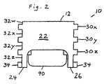
- the terminal nut retainer 10 has a front panel 22, a left side panel 24, a right side panel 26, and a rear panel 28.
- Projections 30x, 30y, and 30z (referred to collectively as projections 30 ) extend from the left side panel 24, the right side panel 26, and the rear panel 28.
- Slots 32w, 32x, 32y, and 32z (referred to collectively as slots 32 ) are formed adjacent the projections 30.
- the projections 30 are tenons, and the slots 32 are mortises. As described below, these tenons and mortises engage mating mortises and tenons in sliding engagement.
- FIG. 3 is a front elevation of the terminal nut retainer 10.
- the locking projections 34 have a ramp 36, which allows the locking projections 34 to slide into position.
- the locking projections 34 have shoulders 38, which hold the terminal nut retainer 10 in a locked position. If desired, shoulders 38 may be angled or inclined toward the front panel 22 to make the terminal nut retainer 10 removable.
- FIG. 3 illustrates that the screw receiving opening 16 has a bottom enclosure 40.
- the screw receiving opening 16 is open toward the top surface 12, but otherwise enclosed by the bottom enclosure 40.
- the bottom enclosure 40 is significant because the enclosure 40 provides insulation.
- the bottom enclosure 40, as well as the entire terminal nut retainer 10, is a dielectric.
- An energized screw (not shown) can be in the screw receiving opening 16, and yet, the screw is insulated, preventing an arc to a grounded surface.
- FIG. 4 shows a left side elevation of the terminal nut retainer 10.
- the bottom enclosure 40 fully encloses a lower portion of the screw receiving opening 16.
- the nut retaining cavity 14 extends to a depth approximately where the projection 30y is located, and the floor 21 provides a transition into the screw receiving opening 16.
- FIG. 5 is a top view of the terminal nut retainer 10.
- the screw receiving opening 16 is defined by inside walls 42 of the bottom enclosure 40.
- FIG. 6 shows a rear elevation of the terminal nut retainer 10. Comparing the rear elevation in FIG. 6 with the front elevation in FIG. 2, the front panel 22 does not extend as low as the rear panel 28.
- the rear panel 28 extends as low as the bottom edge of the projection 30z.
- the front panel 22 extends as low as slightly above the top edge of the projection 30z.
- the front panel 22 provides a strengthening member between the left side panel 24 and the right side panel 26. However, the front panel 22 does not extend any lower so that the left side panel 24 and the right side panel 26 can be squeezed together to allow insertion of the terminal nut retainer 10 into a receptacle.
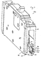
- the terminal nut retainer 10 is shown inserted into its receptacle, and together they comprise a circuit breaker 50.
- a portion of the circuit breaker 50 of FIG. 7 is shown in FIG. 8, but in a bottom perspective view.
- the circuit breaker 50 has mortises or dielectric grooves 52x, 52y, and 52z (referred to collectively as grooves 52) for-receiving the projections 30x, 30y, and 30z, respectively.
- the circuit breaker 50 has tenons or protrusions 53x, 53y, and 53z (referred to collectively as protrusions 53).
- the grooves 52 serve as mortises for the projections 30, which serve as tenons, but for a sliding engagement rather than a fixed joint.
- the protrusions 53 serve as tenons and the slots 32 as mortises.
- the slots 32 and the grooves 52 provide channels for receiving the projections 30 and the protrusions 53.
- the projections 30 and the protrusions 53 slide in the grooves 52 and the slots 32, respectively.
- the circuit breaker 50 also has an engaging slot 54 for receiving and engaging the locking projections 34.
- the grooves 52x, 52y, and 52z are open at their ends adjacent the end 56 of the circuit breaker 50.
- the engaging slot 54 is not open at its two ends adjacent the comer 58 of the circuit breaker 50.
- the grooves 52x, 52y, and 52z receive and guide the projections 30x, 30y, and 30z, respectively.
- the ramps 36 of the locking projections 34 encounter the comers 58 of the circuit breaker 50.
- the locking projections 34 are squeezed together enough for the ramps 36 to slide into the engaging slot 54.
- the ramps 36 are shaped like ramps to provide a gradual incline, allowing the left side panel 24 and the right side panel 26 to be pushed toward each other as the terminal nut retainer 10 is pushed into the grooves 52 and the engaging slot 54.
- the locking projections 34 snap into the depth of the engaging slot 54.
- the shoulders 38 are squared off to prevent the terminal nut retainer 10 from backing out.
- the combination of the ramps 36 and the shoulders 38 provide for one-way insertion of the terminal nut retainer 10.
- the terminal nut retainer 10 cannot be easily removed because the squared-off shoulders 38 engage the engaging slot 54.
- the front panel 22 allows the left side panel 24 and the right side panel 26 sufficient movement for insertion, but the front panel 22 serves as a strengthening member to prevent the terminal nut retainer 10 from backing out of its inserted position. Thus, the terminal nut retainer 10 is retained in a fixed position.
- FIG. 9 shows the base 62 without the cover 64 or the terminal nut retainer 10.
- the grooves 52 and the engaging slot 54 are located below terminals 60x and 60y (referred to collectively as terminal 60). This location positions the terminal nut retainer 10 below the terminal 60.
- the terminal 60 has a hole 62 for receiving a screw (not shown).
- the nut retaining cavity 14 is. located immediately below the hole 62 in the terminal 60.
- the grooves 52 and the engaging slot 54 are molded into a base 62 and a cover 64, which together provide a housing or casing for the circuit breaker 50.
- an electro-mechanical assembly 66 is illustrated with the terminal 60x connected to a first contact and the terminal 60y connected to a second contact for making and breaking a circuit between a source of electricity and a consumer of electricity or load.
- the grooves 52 and the protrusions 53 are illustrated as is the engaging slot 54.
- a nut (not shown), preferably having a lock washer, is placed in the nut retaining cavity 14 with the lock washer toward the top surface 12.
- the terminal nut retainer 10 is inserted into the grooves 52 and the engaging slot 54 until the locking projections 34 snap into a locked position.
- the circuit breaker 50 is then ready for an electrical connector (not shown) to be attached to the terminal 60, without having to take the circuit breaker apart.
- the terminal 60 can be either the electrical source terminal or the electrical load terminal.
- An electrical connector (not shown) is placed adjacent the terminal 60, and a screw (not shown) or similar device is inserted through both the terminal 60 and the electrical connector.
- the screw is then inserted into the nut previously retained in the nut retaining cavity 14 and turned to tightly engage the electrical connector against the terminal 60.
- the terminal nut retainer 10 holds the nut conveniently and securely in place, while providing a dielectric enclosure for the screw and nut.
- the nut retaining cavity 14 is shaped to matingly receive a nut having a like shape. If the nut has a hexagonal shape, then the nut retaining cavity 14 preferably has a hexagonal shape.
- the nut retaining cavity 14 is sized to receive the nut in a reasonably snug engagement so that a screw can be tightened in the nut while the nut is held in a fixed position by the walls 20 and the floor 21 of the nut retaining cavity 14.
- the ridge 18 provides a snug fit, without requiring dose tolerances between the walls 20 and the nut.
- the projections 30 and the protrusions 53 are meshed with the grooves 52 and the slots 32, respectively, somewhat like the dovetailing of a tenon with a mortise.
- the interlocking of the locking projections 34 with the engaging slot 54 prevents the terminal nut retainer 10 from sliding out of its fixed position.
- the meshing of the projections 30 and the protrusions 53 with the slots 52 and the slots 32, respectively, allows the terminal nut retainer 10 to withstand a significant amount of force from a direction transverse to the sliding engagement This arrangement allows the terminal nut retainer 10 to withstand a significant amount of downward force as a screw is pushed down into the retained nut and turned.
- the present invention provides a circuit breaker 50 having a terminal nut retainer 10 for securely holding a nut in a fixed position adjacent and below the circuit breaker terminal 60.
- the circuit breaker is placed in a circuit by securing a source electrical connector to the source terminal 60 and/or a load electrical connector to the load terminal 60.
- a screw is used to engage the nut and fasten the electrical connector to its respective terminal 60.
- the walls 20 of the nut retaining cavity 14 prevent the nut from turning while the screw is tightened.
- the projections 30 mesh with the grooves 52 to place the nut.in a proper position and to withstand a transverse force that the terminal nut retainer 10 encounters when the screw is pushed into the nut as it is turned.
- the bottom enclosure 40 insulates the portion of the screw that protrudes through the nut to prevent an arc to a grounded surface.
Landscapes
- Breakers (AREA)
- Connections Arranged To Contact A Plurality Of Conductors (AREA)
- Connections By Means Of Piercing Elements, Nuts, Or Screws (AREA)
Claims (10)
- Schutzschalter (50) zum Unterbrechen des Stroms in einem Schaltkreispfad zwischen einer Quelle und einer Last, aufweisend eine elektromechanische Anordnung mit einem ersten und einen zweiten Kontakt, die im Schaltkreispfad zusammenarbeiten, um der Last von der Quelle Strom zuzuführen, wobei wenigstens einer der Kontakte beweglich ist, um den Strom, der der Last zugeführt wird, zu unterbrechen, einem Anschluß (60), der an dem ersten Kontakt angeschlossen ist, und einem Gehäuse (50) zum Aufnehmen der elektromechanischen Anordnung,
gekennzeichnet durch
eine Anschlußmutter-Haltevorrichtung (10), die mit dem Gehäuse in der Nähe des Anschlusses verrastet ist, wobei die Anschlußmutter-Haltevorrichtung einen Rumpf und eine Ausnehmung (14) zum Haltern der Mutter hat und eine Feder (30) und eine Nut (32) benachbart zur Feder zur Gleitverbindung mit dem Gehäuse (50) und einen Vorsprung (34) zum Verrasten mit dem Gehäuse hat. - Schutzschalter nach Anspruch 1, bei dem der Rumpf erste gegenüberliegende Seiten (24, 26) und einen ersten Vorsprung an einer der ersten gegenüberliegenden Seiten hat.
- Schutzschalter nach Anspruch 2, bei dem das Gehäuse einen ersten Schlitz (54) zum Aufnehmen des ersten Vorsprungs hat.
- Schutzschalter nach Anspruch 3, bei dem der Rumpf eine Oberseite (12) und eine Unterseite hat, und die Ausnehmung an der Oberseite offen und an der Unterseite geschlossen ist.
- Schutzschalter nach Anspruch 4, bei dem die Anschlußmutter-Haltevorrichtung ein Dielektrikum ist.
- Schutzschalter nach Anspruch 5, bei dem der Rumpf eine Platte (22) zwischen den ersten gegenüberliegenden Seiten hat.
- Schutzschalter nach Anspruch 6, bei dem der Rumpf einen zweiten Vorsprung an einer der ersten gegenüberliegenden Seiten gegenüber dem ersten Vorsprung hat.
- Schutzschalter nach Anspruch 6, bei dem das Gehäuse einen zweiten Schlitz zum Aufnehmen des zweiten Vorsprungs hat.
- Schutzschalter nach Anspruch 1, bei dem die Anschlußmutter-Haltevorrichtung ein geformtes Dielektrikum ist, aufweisend einen Rumpf mit einer Kastenform mit einer Oberseite, einer Unterseite, und wobei die Ausnehmung im Rumpf zum Aufnehmen der Mutter durch die Wände (20) gebildet ist und an der Oberseite offen ist.
- Verfahren zum Haltern einer Mutter in der Nähe eines Anschlusses, aufweisend das Anordnen des Anschlusses in einem Gehäuse (50) mit gegenüberliegenden Nuten (52) und gegenüberliegenden Schlitzen (54) unterhalb der Anschlüsse, Formen einer Anschlußmutter-Haltevorrichtung (10) aufweisend einen Rumpf mit einer Ausnehmung (14) zum Haltern der Nut und gegenüberliegende Seiten (24, 26), wobei die Seiten Vorsprünge (30) zur Gleitverbindung mit den Nuten und Einrastvorsprünge (34) zum Einrasten in den Schlitzen haben, Anordnen der Mutter in der Ausnehmung und Einsetzen der Anschlußmutter-Haltevorrichtung in das Gehäuse, wobei die Vorsprünge gleitbeweglich in die Nuten eingreifen und die Einrastvorsprünge in den Schlitzen einrasten.
Applications Claiming Priority (3)
| Application Number | Priority Date | Filing Date | Title |
|---|---|---|---|
| US644508 | 1996-05-10 | ||
| US08/644,508 US5772479A (en) | 1996-05-10 | 1996-05-10 | Circuit breaker with terminal nut retainer |
| PCT/US1997/007952 WO1997043778A1 (en) | 1996-05-10 | 1997-05-12 | Circuit breaker with terminal nut retainer |
Publications (2)
| Publication Number | Publication Date |
|---|---|
| EP0838079A1 EP0838079A1 (de) | 1998-04-29 |
| EP0838079B1 true EP0838079B1 (de) | 2002-07-10 |
Family
ID=24585207
Family Applications (1)
| Application Number | Title | Priority Date | Filing Date |
|---|---|---|---|
| EP97924663A Expired - Lifetime EP0838079B1 (de) | 1996-05-10 | 1997-05-12 | Schutzschalter mit anschlussmutterhaltervorrichtung |
Country Status (6)
| Country | Link |
|---|---|
| US (1) | US5772479A (de) |
| EP (1) | EP0838079B1 (de) |
| JP (1) | JPH11509968A (de) |
| CA (1) | CA2226500A1 (de) |
| DE (1) | DE69713853T2 (de) |
| WO (1) | WO1997043778A1 (de) |
Families Citing this family (17)
| Publication number | Priority date | Publication date | Assignee | Title |
|---|---|---|---|---|
| US6172586B1 (en) * | 1999-11-05 | 2001-01-09 | Siemens Energy & Automation Inc. | Terminal barrier system for molded case circuit breaker |
| US6379196B1 (en) | 2000-03-01 | 2002-04-30 | General Electric Company | Terminal connector for a circuit breaker |
| DE10018351C2 (de) * | 2000-04-13 | 2002-07-04 | Siemens Ag | Klemme |
| US6255927B1 (en) * | 2000-05-15 | 2001-07-03 | Eaton Corporation | Cable lug conductor adapter device |
| US6624375B2 (en) | 2001-04-04 | 2003-09-23 | Siemens Energy & Automation, Inc. | Wire lug/arc vent barrier molded case circuit breaker |
| US6529112B1 (en) | 2001-06-13 | 2003-03-04 | Siemens Energy & Automation, Inc. | Ring tongue lug retainer molded case circuit breaker |
| US6554366B2 (en) * | 2001-09-14 | 2003-04-29 | L & P Property Management Company | Nut plate retainer |
| JP2004327185A (ja) * | 2003-04-23 | 2004-11-18 | Yazaki Corp | 端子台 |
| JP4341464B2 (ja) * | 2004-05-11 | 2009-10-07 | 富士電機機器制御株式会社 | 電気機器の端子装置 |
| DE102004046808B3 (de) * | 2004-09-27 | 2006-04-27 | eupec Europäische Gesellschaft für Leistungshalbleiter mbH | Anschlussteil und Verfahren zum Herstellen eines Anschlussteils |
| US7578960B2 (en) * | 2005-09-22 | 2009-08-25 | Ati Properties, Inc. | Apparatus and method for clean, rapidly solidified alloys |
| US7633365B2 (en) * | 2007-06-28 | 2009-12-15 | General Electric Company | Circuit breaker apparatus |
| JP5278754B2 (ja) * | 2009-04-23 | 2013-09-04 | 住友電装株式会社 | 機器用コネクタ |
| DE102009041034A1 (de) * | 2009-09-14 | 2011-03-17 | Siemens Aktiengesellschaft | Steckanschluss für ein elektrisches Schaltgerät sowie elektrisches Schaltgerät mit einem derartigen Steckanschluss |
| DE102010033236A1 (de) | 2010-07-29 | 2012-02-02 | Siemens Aktiengesellschaft | Elektrischer Schalter |
| US20130322050A1 (en) * | 2012-05-31 | 2013-12-05 | Daniel Douglas David | Modular circuit breaker, kit, and methods of manufacture and assembly |
| DE102020203056A1 (de) | 2020-03-10 | 2021-09-16 | Te Connectivity Germany Gmbh | Elektrische Schaltvorrichtung, insbesondere ein Stromschütz oder ein Relais, mit Kontaktierungselement und Befestigungselement |
Family Cites Families (20)
| Publication number | Priority date | Publication date | Assignee | Title |
|---|---|---|---|---|
| DE141885C (de) * | ||||
| US2614196A (en) * | 1948-09-16 | 1952-10-14 | Hoover Co | Switch casing |
| DE1032356B (de) * | 1955-09-17 | 1958-06-19 | Voigt & Haeffner Ag | Elektrischer Kontakt aus blechartigem Material mit Schraubenklemme am Anschlussende |
| DE2500141A1 (de) * | 1974-01-23 | 1975-07-24 | Gen Signal Corp | Elektrisches anschlusstueck mit variabler laenge |
| US4171862A (en) * | 1977-04-09 | 1979-10-23 | Ellenberger & Poensgen Gmbh | Terminal board for electrical equipment |
| GB2078012B (en) * | 1980-06-13 | 1983-12-07 | Honeywell Ltd | Electrical changeover switch |
| FR2614473B1 (fr) * | 1987-04-22 | 1989-07-07 | Power Compact | Borne a ecrou prisonnier pour connecteur de puissance de modules electroniques |
| US4864263A (en) * | 1987-09-03 | 1989-09-05 | General Electric Company | Molded case circuit breaker latch and operating mechanism assembly |
| US4809132A (en) * | 1987-10-23 | 1989-02-28 | General Electric Co. | Field installable line and load lug connectors for molded case circuit breakers |
| US4796844A (en) * | 1987-11-27 | 1989-01-10 | Ronald Barker | Bracket for use in securing an electric meter base |
| US4831221A (en) * | 1987-12-16 | 1989-05-16 | General Electric Company | Molded case circuit breaker auxiliary switch unit |
| US4794356A (en) * | 1987-12-16 | 1988-12-27 | General Electric Company | Molded case circuit breaker auxiliary switch unit |
| US4912439A (en) * | 1989-01-27 | 1990-03-27 | General Electric Company | Molded case circuit breaker auxiliary switch unit |
| US5252937A (en) * | 1990-08-09 | 1993-10-12 | General Electric Company | Molded case circuit breaker modular bell alarm unit |
| US5172088A (en) * | 1992-02-06 | 1992-12-15 | General Electric Company | Molded case circuit breaker combined accessory actuator-reset lever |
| US5272592A (en) * | 1992-09-30 | 1993-12-21 | Square D Company | Panelboard interior assembly |
| US5272591A (en) * | 1992-09-30 | 1993-12-21 | Square D Company | Protective cover for electrical bus bars |
| US5430419A (en) * | 1994-01-13 | 1995-07-04 | Square D | Double break circuit breaker having improved secondary section |
| US5404266A (en) * | 1994-01-31 | 1995-04-04 | General Electric Company | Temporary power center for construction site |
| US5418683A (en) * | 1994-02-07 | 1995-05-23 | General Electric Company | Temporary power center for construction site |
-
1996
- 1996-05-10 US US08/644,508 patent/US5772479A/en not_active Expired - Fee Related
-
1997
- 1997-05-12 DE DE69713853T patent/DE69713853T2/de not_active Expired - Fee Related
- 1997-05-12 EP EP97924663A patent/EP0838079B1/de not_active Expired - Lifetime
- 1997-05-12 JP JP9540993A patent/JPH11509968A/ja active Pending
- 1997-05-12 WO PCT/US1997/007952 patent/WO1997043778A1/en not_active Ceased
- 1997-05-12 CA CA002226500A patent/CA2226500A1/en not_active Abandoned
Also Published As
| Publication number | Publication date |
|---|---|
| DE69713853D1 (de) | 2002-08-14 |
| JPH11509968A (ja) | 1999-08-31 |
| US5772479A (en) | 1998-06-30 |
| WO1997043778A1 (en) | 1997-11-20 |
| DE69713853T2 (de) | 2003-03-13 |
| CA2226500A1 (en) | 1997-11-20 |
| EP0838079A1 (de) | 1998-04-29 |
Similar Documents
| Publication | Publication Date | Title |
|---|---|---|
| US5772479A (en) | Circuit breaker with terminal nut retainer | |
| US5761026A (en) | Snap-on circuit breaker mounting system | |
| US6333846B1 (en) | Power supply shut-off apparatus | |
| US5539168A (en) | Power circuit breaker having a housing structure with accessory equipment for the power circuit breaker | |
| US4809132A (en) | Field installable line and load lug connectors for molded case circuit breakers | |
| US6062914A (en) | Circuit breaker plug in bracket and auxiliary/alarm switch connector for use therewith | |
| CA1081769A (en) | Electrical receptacle equipped with ground fault protection | |
| CN112534651B (zh) | 具有端子位置保证装置的电连接器 | |
| EP1975966B1 (de) | Elektrisches Schaltgerät und Verriegelung der Phasentrennung dafür | |
| CA1081768A (en) | Ground fault receptacle with improved stationary contact mounting and backing | |
| MXPA01012554A (es) | Portafusibles modular. | |
| US6232859B1 (en) | Auxiliary switch mounting configuration for use in a molded case circuit breaker | |
| US5863219A (en) | Device for fastening of electric equipment on an adapter | |
| EP1383203B1 (de) | Elektrischer Verbinder mit Überspannungsschutz | |
| CA2300532A1 (en) | Socket-type circuit breaker mounting system | |
| EP0788205A2 (de) | Verbesserung von elektrischen Verteilungsgeräten | |
| JPH07335305A (ja) | 電気コネクタ及びそのハウジング | |
| US5909019A (en) | Front mounting plate with integral locking tab | |
| GB2310768A (en) | Distribution equipment for a wall mountable consumer unit | |
| WO1996024941A1 (en) | Secondary disconnect assembly for high ampere-circuit breaker | |
| JP3272248B2 (ja) | サービスプラグのレバー保持機構 | |
| CA1266307A (en) | Bus bar stab and insulator assembly for a motor controller | |
| MXPA98000289A (es) | Disyuntor de circuito con reten de tuerca terminal | |
| MXPA01011738A (es) | Soporte de interruptor de circuito y ensamble de interruptor de circuito. | |
| JP2000243483A (ja) | 端子装置および分電盤 |
Legal Events
| Date | Code | Title | Description |
|---|---|---|---|
| PUAI | Public reference made under article 153(3) epc to a published international application that has entered the european phase |
Free format text: ORIGINAL CODE: 0009012 |
|
| 17P | Request for examination filed |
Effective date: 19980207 |
|
| AK | Designated contracting states |
Kind code of ref document: A1 Designated state(s): CH DE FR GB IT LI SE |
|
| RIN1 | Information on inventor provided before grant (corrected) |
Inventor name: SIEBELS, RANDALL, LUTHER Inventor name: FRANCIS JR, DONALD CHARLES Inventor name: FLEEGE, DENNIS WILLIAMS |
|
| 17Q | First examination report despatched |
Effective date: 20000210 |
|
| GRAG | Despatch of communication of intention to grant |
Free format text: ORIGINAL CODE: EPIDOS AGRA |
|
| GRAG | Despatch of communication of intention to grant |
Free format text: ORIGINAL CODE: EPIDOS AGRA |
|
| GRAH | Despatch of communication of intention to grant a patent |
Free format text: ORIGINAL CODE: EPIDOS IGRA |
|
| GRAH | Despatch of communication of intention to grant a patent |
Free format text: ORIGINAL CODE: EPIDOS IGRA |
|
| RIN1 | Information on inventor provided before grant (corrected) |
Inventor name: SIEBELS, RANDALL, LUTHER Inventor name: FRANCIS JR, DONALD CHARLES Inventor name: FLEEGE, DENNIS WILLIAMS |
|
| GRAA | (expected) grant |
Free format text: ORIGINAL CODE: 0009210 |
|
| AK | Designated contracting states |
Kind code of ref document: B1 Designated state(s): CH DE FR GB IT LI SE |
|
| PG25 | Lapsed in a contracting state [announced via postgrant information from national office to epo] |
Ref country code: LI Free format text: LAPSE BECAUSE OF FAILURE TO SUBMIT A TRANSLATION OF THE DESCRIPTION OR TO PAY THE FEE WITHIN THE PRESCRIBED TIME-LIMIT Effective date: 20020710 Ref country code: IT Free format text: LAPSE BECAUSE OF FAILURE TO SUBMIT A TRANSLATION OF THE DESCRIPTION OR TO PAY THE FEE WITHIN THE PRE;WARNING: LAPSES OF ITALIAN PATENTS WITH EFFECTIVE DATE BEFORE 2007 MAY HAVE OCCURRED AT ANY TIME BEFORE 2007. THE CORRECT EFFECTIVE DATE MAY BE DIFFERENT FROM THE ONE RECORDED.SCRIBED TIME-LIMIT Effective date: 20020710 Ref country code: CH Free format text: LAPSE BECAUSE OF FAILURE TO SUBMIT A TRANSLATION OF THE DESCRIPTION OR TO PAY THE FEE WITHIN THE PRESCRIBED TIME-LIMIT Effective date: 20020710 |
|
| REG | Reference to a national code |
Ref country code: GB Ref legal event code: FG4D |
|
| REG | Reference to a national code |
Ref country code: CH Ref legal event code: EP |
|
| REF | Corresponds to: |
Ref document number: 69713853 Country of ref document: DE Date of ref document: 20020814 |
|
| PG25 | Lapsed in a contracting state [announced via postgrant information from national office to epo] |
Ref country code: SE Free format text: LAPSE BECAUSE OF FAILURE TO SUBMIT A TRANSLATION OF THE DESCRIPTION OR TO PAY THE FEE WITHIN THE PRESCRIBED TIME-LIMIT Effective date: 20021010 |
|
| ET | Fr: translation filed | ||
| REG | Reference to a national code |
Ref country code: CH Ref legal event code: PL |
|
| PG25 | Lapsed in a contracting state [announced via postgrant information from national office to epo] |
Ref country code: GB Free format text: LAPSE BECAUSE OF NON-PAYMENT OF DUE FEES Effective date: 20030512 |
|
| PLBE | No opposition filed within time limit |
Free format text: ORIGINAL CODE: 0009261 |
|
| STAA | Information on the status of an ep patent application or granted ep patent |
Free format text: STATUS: NO OPPOSITION FILED WITHIN TIME LIMIT |
|
| 26N | No opposition filed |
Effective date: 20030411 |
|
| PG25 | Lapsed in a contracting state [announced via postgrant information from national office to epo] |
Ref country code: DE Free format text: LAPSE BECAUSE OF NON-PAYMENT OF DUE FEES Effective date: 20031202 |
|
| GBPC | Gb: european patent ceased through non-payment of renewal fee |
Effective date: 20030512 |
|
| PG25 | Lapsed in a contracting state [announced via postgrant information from national office to epo] |
Ref country code: FR Free format text: LAPSE BECAUSE OF NON-PAYMENT OF DUE FEES Effective date: 20040130 |
|
| REG | Reference to a national code |
Ref country code: FR Ref legal event code: ST |