EP0838201A1 - Steuergerät zum Anschluss von zahnärztlichen, zahntechnischen oder feinwerktechnischen Behandlungsinstrumenten oder Handstücken - Google Patents
Steuergerät zum Anschluss von zahnärztlichen, zahntechnischen oder feinwerktechnischen Behandlungsinstrumenten oder Handstücken Download PDFInfo
- Publication number
- EP0838201A1 EP0838201A1 EP97118543A EP97118543A EP0838201A1 EP 0838201 A1 EP0838201 A1 EP 0838201A1 EP 97118543 A EP97118543 A EP 97118543A EP 97118543 A EP97118543 A EP 97118543A EP 0838201 A1 EP0838201 A1 EP 0838201A1
- Authority
- EP
- European Patent Office
- Prior art keywords
- control device
- handpieces
- connection
- drive systems
- control unit
- Prior art date
- Legal status (The legal status is an assumption and is not a legal conclusion. Google has not performed a legal analysis and makes no representation as to the accuracy of the status listed.)
- Granted
Links
- 230000008878 coupling Effects 0.000 claims description 37
- 238000010168 coupling process Methods 0.000 claims description 37
- 238000005859 coupling reaction Methods 0.000 claims description 37
- 238000001514 detection method Methods 0.000 claims description 18
- 238000003860 storage Methods 0.000 claims description 12
- 230000005291 magnetic effect Effects 0.000 abstract description 5
- 230000005693 optoelectronics Effects 0.000 abstract description 2
- 239000003570 air Substances 0.000 description 27
- 238000009826 distribution Methods 0.000 description 14
- XLYOFNOQVPJJNP-UHFFFAOYSA-N water Substances O XLYOFNOQVPJJNP-UHFFFAOYSA-N 0.000 description 10
- 238000010586 diagram Methods 0.000 description 6
- 238000005516 engineering process Methods 0.000 description 5
- 238000001816 cooling Methods 0.000 description 4
- 230000008901 benefit Effects 0.000 description 3
- 210000003127 knee Anatomy 0.000 description 3
- 238000003754 machining Methods 0.000 description 3
- KGSSUTVUTPLSQW-UHFFFAOYSA-N Robustone Chemical compound C1=C2OCOC2=CC(C2=COC=3C=C4OC(C=CC4=C(O)C=3C2=O)(C)C)=C1 KGSSUTVUTPLSQW-UHFFFAOYSA-N 0.000 description 2
- 239000000919 ceramic Substances 0.000 description 2
- 230000008859 change Effects 0.000 description 2
- 230000001419 dependent effect Effects 0.000 description 2
- 239000007921 spray Substances 0.000 description 2
- 230000004888 barrier function Effects 0.000 description 1
- 238000005266 casting Methods 0.000 description 1
- 238000004140 cleaning Methods 0.000 description 1
- 238000000151 deposition Methods 0.000 description 1
- 239000012530 fluid Substances 0.000 description 1
- 230000004907 flux Effects 0.000 description 1
- 238000000227 grinding Methods 0.000 description 1
- 230000006698 induction Effects 0.000 description 1
- 230000007257 malfunction Effects 0.000 description 1
- 238000000034 method Methods 0.000 description 1
- 238000003801 milling Methods 0.000 description 1
- 239000000203 mixture Substances 0.000 description 1
- 229920003023 plastic Polymers 0.000 description 1
- 239000004033 plastic Substances 0.000 description 1
- 239000010970 precious metal Substances 0.000 description 1
- 230000008569 process Effects 0.000 description 1
- 238000007789 sealing Methods 0.000 description 1
- 229910000859 α-Fe Inorganic materials 0.000 description 1
Images




Classifications
-
- A—HUMAN NECESSITIES
- A61—MEDICAL OR VETERINARY SCIENCE; HYGIENE
- A61C—DENTISTRY; APPARATUS OR METHODS FOR ORAL OR DENTAL HYGIENE
- A61C1/00—Dental machines for boring or cutting ; General features of dental machines or apparatus, e.g. hand-piece design
- A61C1/0007—Control devices or systems
-
- A—HUMAN NECESSITIES
- A61—MEDICAL OR VETERINARY SCIENCE; HYGIENE
- A61C—DENTISTRY; APPARATUS OR METHODS FOR ORAL OR DENTAL HYGIENE
- A61C1/00—Dental machines for boring or cutting ; General features of dental machines or apparatus, e.g. hand-piece design
- A61C1/0007—Control devices or systems
- A61C1/0015—Electrical systems
- A61C1/0023—Foot control
Definitions
- the invention relates to a control device for connecting one or more dental, dental or precision engineering treatment instruments or Handpieces according to the preamble of claim 1.
- German utility model DE 92 18 191 U1 a device for control and Power supply of several consumers of a dental treatment center with one central energy supply unit and with a control unit that reveals all Consumers common power module, which is dependent on Control signals from the control unit provide the right supply media for every consumer provides.
- From DE 42 20 006 A1 is a control system for several dental handpieces and associated facilities known, which controls the supply of air and water, the fluids being fed through a single manifold.
- control systems are capable of several various processing tools or treatment tools according to their Characteristics and their use with the required equipment (electrical current, Compressed air, water, etc.).
- required equipment electrical current, Compressed air, water, etc.
- control system only devices are connected and controlled, their drive systems are based on the same physical principle.
- the drive systems of all instruments used with the same setting and / or actuating elements e.g. knee switch, Foot rocker arm, potentiometer, foot switch
- switchable and controllable e.g.
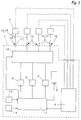
- Fig. 1 shows a block diagram for explaining the operation of a first Embodiment.
- the components of the control device 1 according to the invention are shown within the dashed rectangle.
- the control device 1 shown contains three different supply units 2 for Different drive systems, for example for three-phase motors, for brushless ones DC motors and for collector motors.
- the power outputs of the three Supply units 2 rest on appropriately trained connection devices 3.
- connection devices 3 treatment instruments or Handpieces 4 with different drive systems are connected, being on it It is important to ensure that the instruments or handpieces 4 correspond to those of their Drive systems require supply to the appropriate connection device 3 be connected.
- the connection devices 3 are depending on Supply unit 2 or depending on the drive system to be controlled characteristic and distinguishable so that incorrect connection by the user can be excluded.
- connection devices 3 are used for the use of several Instruments or handpieces 4 of the same drive type.
- control unit 1 a number of connection devices 3 to be expanded by the same Supply unit 2 can be controlled.
- connection devices 3 for one The supply unit 2 must be analogous to the above distribution device 5 between parallel Connection devices 3 and supply unit 2 also a distribution device are switched or arranged, each only one, the instrument used or handpiece 4 controls or connects the corresponding connecting device 3.
- control device 1 is advantageously used for the purpose of simpler extension of connecting devices 3 constructed modularly.
- control unit 1 contains a Detection device 6. This detection device 6 recognizes which instrument or Handpiece 4 was removed from its storage, and indicates a corresponding signal a central control unit 7 in control unit 1.
- the detection device 6 consists of switching elements directly on Control unit 1 or external switching elements on the instruments or handpieces 4 or the trays through which the user manually removes the treatment instrument or handpiece 4. Some are also from the general state of the art further devices for automatic detection of the removal of a Treatment instrument or handpiece 4 known from a storage device.
- Handpiece 4 can be encoded with a characteristic resistance value. After Removal of a handpiece 4 from the corresponding storage device connected resistance value measured and based on the measured Resistance value based on the connected instrument type.
- Another variant for recording the removal of an instrument or handpiece 4 is based on an opto-electronic principle.
- the removal or storage of the instruments or handpieces 4 is detected, for example, via light barriers connected to the Trays are provided.
- the detection device 6 recognizes the storage position of the removed instrument or handpiece 4 and thus also the connection device 3 via which the relevant Instrument 4 can be controlled. This data is from the capture device 6 transmitted to the central control unit 7.
- the control unit 7 determines on the basis of that from the detection device 6 transmitted data the type of the removed instrument or handpiece 4, i.e. especially the drive system and the necessary equipment. This can be done using, for example suitable software and a control table integrated in the control unit 7. According to this result, the corresponding supply unit 2 and corresponding connection device 3 controlled with the required parameters. In the event of of several instruments 4 connected to a connecting device 3 must be from the control unit 7 also control data for the correct choice of the output of the Distribution device 5 are transmitted. Likewise, in the case of several at one Supply unit 2 of connected connecting devices 3 by the control unit 7 the right choice of connector 3 can be controlled.
- the set operating parameters and other information, such as Device type, connection device, drive type, speed, water supply, Air supply, error messages, times and the like, of the removed instrument or handpiece 4 can optionally via one or more internal and / or external Display devices 8 are displayed to the user.
- the display devices 8 are preferably located directly on control unit 1 and / or in the user's field of vision.
- the user has the option of using one of them via an input device 9
- Enter the desired speed for the removed instrument or handpiece 4 is set by the control unit 7 via the corresponding supply unit 2.
- at least one display field for the rotational speed should be in the display device 8 be provided.
- the automatic specification of an average is also particularly advantageous Speed by the control unit 7 after detection of the type of instrument removed, the corresponds to an average speed for a typical application of the instrument type. Starting from this average speed setting by the control unit 7, the If necessary, the user can quickly change the speed to the desired value correct.
- control unit 7 of the control unit 1 with a switch 10 for Commissioning of the respective instrument or handpiece 4 connected.
- the Control data are indeed from the time of removal of the supply units 2 and the instruments or handpieces 4 transmitted, for safety reasons the instruments or handpieces 4 are only put into operation when this is done by User is desired.
- commissioning of the instruments or Handpieces 4 locked by the control unit 7 as long as the instruments or Handpieces 4 are in their storage.
- switches 10 for example, foot switches, foot rocker arms, knee switch plates, Potentiometers or other known types of switches can be used. It is also conceivable the functions of speed selection and start-up of handpiece 4 together via to be able to enter a combined switch.
- Instruments or handpieces 4 All connected can via switch 10 and speed input device 9 Instruments or handpieces 4, also different drive systems, in the same way operate. There are therefore not a plurality of switches 10 and / or input devices 9 necessary for the operation of the instruments or handpieces 4.
- FIG. 2 now shows a first exemplary embodiment of a control device 1 according to the invention shown.
- the control device 1 shown corresponds to the block diagram described above of Fig. 1st
- the control unit 1 has three electrical connection devices 3 for connecting three various electrical drive systems. Instead of or in addition to electrical connection devices 3 can of course also pneumatic Connection devices can be attached to the control unit 1. As a detection device for Selection of the desired instrument or handpiece 4 is via the Connection devices 3 switches 6 attached to display the selected Instruments 4 can also be stored with light-emitting diodes.
- control device has a display device 8 in the form of an LCD display, a rotary knob as a speed input device 9 and a switch 10 for Commissioning of the instrument or handpiece 4.
- display device 8 in the form of an LCD display
- rotary knob as a speed input device 9
- switch 10 for Commissioning of the instrument or handpiece 4.
- an external connection device Display device connectable (not shown).
- FIG. 3 shows a control unit 1 with a central control unit 7, the three supply units 2 for different Drive systems controls, a detection device 6 to recognize which Instrument or handpiece 4 was removed from its storage, at least one Display device 8, a speed input device 9 and a switch 10 for Commissioning of the respective instrument or handpiece 4.
- this control device has several, e.g. four, universal connection devices 11, to which via universal connecting elements Instruments or handpieces 4 any electrical Drive systems can be connected.
- any electrical Drive systems can be connected.
- distribution devices 5 several instruments or Handpieces 4 can be connected to a connecting device 11, or the control unit 1 can be expanded by a number of universal connection devices 11.
- connection devices 11 over the specific ones Connection devices 3 for the user is obvious. For one thing, anyone can any instrument or handpiece 4 connected to each connector 11 and on the other hand the number of existing connection devices 11 always be used optimally. In the case of the specific connection devices 3 it can happen that an expansion of the control unit 1 or the use of Distribution devices 5 is necessary, although not all of the existing ones Connection devices 3 are occupied, for example, for a drive system none Instruments or handpieces are needed.
- control unit 12 To each of the universal connection devices 11 with each supply unit 2 for the Different drive systems must be connected between the supply units 2 and the connection devices 11 a control unit 12 are switched.
- the Control unit 12 enables all possible control connections between the three Supply units 2 and the four connection devices 11 and switches accordingly a control signal from the central control unit 7 in each case the required connection by.
- FIG. 4 One corresponding to the mode of operation of the block diagram of FIG. 3 Exemplary embodiment of a control device 1 is shown in FIG. 4. From the outer structure ago this control unit 1 essentially corresponds to the first embodiment. In this embodiment, however, the three connection devices are universal Connection devices 11 for connecting instruments or handpieces 4 any drive systems.
- Fig. 5 is a third embodiment of an analog Control unit 1 according to the invention shown.
- the control unit 1 of this Embodiment combines the functions of the first two Embodiments, i.e. its mode of operation corresponds to a combination of the two 1 and 3.
- control unit 1 is a pneumatic Connection device 13 attached.
- connection device 13 are instruments or handpieces 4 with pneumatic drive systems, such as air turbines, connectable.
- the connecting device 13 is, of course, of further pneumatic type Connection devices 13 expandable to several with the control unit 1 Connect and control compressed air operated instruments or handpieces 4 at the same time to be able to.
- one or more (not shown) distribution devices for Connection of several instruments or handpieces 4 to a connection device 13 conceivable.
- the distribution device corresponds to the electrical one explained above Distribution device 5 only that, of course, instead of electrical lines and switches Compressed air lines and switches must be used.
- a merger of the two connection devices 3 or 11 and 13 to only one only universal connection device is due to the complexity of the alien Supply lines and controls obviously do not make sense, since the effort required User benefit exceeds.
- the instruments or handpieces 4 are one or more Supply lines 15 for media formed by the operating resources assigned in the Functional operation for driving and cooling the handpiece and / or for cooling and / or for rinsing and / or cleaning and / or illuminating the treatment site to be used.
- These are electrical lines that are used to supply serve electrical current or, in particular, flexible pipelines, the feeder air or water or a water / air mixture (spray).
- connection devices can each in the sense of the non-universal connection devices 3 or 3a or the universal Connection devices 11 can be provided to also several treatment instruments or handpieces 4 can be connected without and with distribution devices.
- a Treatment instrument or handpiece 4 simple function as is the case with the air hand nozzle 4c can be the case, a special simple connection device can also be provided be.
- the motor handpiece 4a Drive motor 16 extending first electrical line 15a for drive current, one to a lighting device arranged at the front end of the motor handpiece 4a 19 extending second electrical line 15b and one or more air lines, the each separately or as line branches to an air cooling device 21 for the Drive motor 16, to a rotary bearing 22 supported by compressed air for one Machining tool 23 holding drive shaft 24 of the motor handpiece 4a and to one Air nozzle 25 arranged in the front end region of motor handpiece 4a.
- two air lines 15c, 15d are provided, from those designated by 15c to the cooling device 21 and to the pivot bearing 22 branches and the 15d extends to the air nozzle 25. It is possible and depending on the purpose of use, also advantageous, in addition one not shown Provide water pipe that extends to a in the front end of the motor handpiece 4a extends arranged water nozzle, which can be combined with the air nozzle 25.
- a drive air line 15e is provided for the turbine handpiece 4b a turbine 26 arranged in the front end region of the turbine handpiece 4b extends a rotary drive of a machining tool 23, an electrical line 15f, which extends to one in the front end region of the turbine handpiece 4b Lighting device 19 extends, a blown air line 15g, and a water line 15h, each for an air, water or spray outlet also in the front Extend the end region of the turbine handpiece 4b.
- Air line 15i may be arranged.
- Each media line 15 has in the area of the respective through the connection device 3 or 3a or 11 formed, preferably designed as a plug-in coupling, a pair Connecting elements or coupling elements for connecting or coupling the associated media line 15, which when coupling or uncoupling with Coupling part 18 are automatically connected or released and each as Quick or preferably plug-in coupling designed sine.
- a closure element preferably an in Direction to the coupling part 18 automatically closing check valve provided, that opens automatically when coupling and closes automatically when disconnected.
- the connecting devices 3, 3a, 11 and / or 13 not on the control unit 1st but preferably in the rear area of the treatment instrument or instruments Handpieces 4, in particular between a rear connector 4.1 and a front Arrange instrument part 4.2, which is z. B. can be a handpiece 4.
- the rear connector 4.1 and the front instrument part 4.2 are by a Quick coupling, in particular in the form of a plug-in coupling or plug-in / rotary coupling 31 connectable to each other and shown in Fig. 6 in the connected position.
- the z. B. radial dividing line between the rear connector 4.1 and the front Instrument part 4.2 is designated 32.
- the Plug-in / rotary coupling 31 an axial cylindrical or step-cylindrical Coupling pin 33a, which rotates with little movement in a coupling hole 33b can be inserted.
- the coupling pin 33a can 4.2 protrude to the rear or protrude from the rear connection part 34.1 as is is shown.
- the coupling hole 33b is in the other of the aforementioned parts available.
- To secure the plug-in / rotary coupling 31 in the assembled Coupling position is one between the coupling pin 33a and the coupling hole 33b effective locking device 34 provided manually by an appropriate Tractive force can be suppressed and is therefore easy to handle.
- the media lines, here 15b to 15d, pass through the plug-in / rotary coupling 31, being the hollow cylindrical one Gap 32a between the coupling pin 33a and the coupling hole 33b Z-shaped push through sealed.
- connection devices 3, 3a, 11 or 13 are the aforementioned connection devices in contrast to the device side Connection devices with the same position numbers, however, each supplemented by .1 clarified, namely with 3.1, 3a.1, 11.1 and 13.1.
- This configuration is among others advantageous because the treatment tool or handpieces 4 without the Supply lines 17 can be connected, the supply lines 17 can remain on the control unit 1. With this configuration, therefore need in Connection area of the supply lines 17 on the device 1 none according to the invention Connection devices 3, 3a, 11 or 13 to be arranged.
- connecting devices ensuring the passage of the media.
- An arrangement of the connecting devices according to the invention on the instrument side is required in the presence of a specific connection device 3.1, 3a.1, in principle according to the connection device 3 or 3a described above, the presence the specific media lines in the connected to the rear connector 4.1 Supply line 17 and in the presence of a universal connection device 11.1 the presence of all media lines in the associated supply line 17.
- the other treatment instruments or handpieces 4b, 4c are related to the Connection devices 3.1, 3a.1, 11.1, 13.1 designed accordingly.
- the detection elements of the detection device 6 can, as already described, with the respective trained in the sense of the connection device 3 or 3a or 11 Coupling part 18, 18.1 cooperate so that the respective controls 7 and 12, respectively the associated handpiece 4 controls the respective operating parameters. This also applies to the associated medium, the line 15 activated and possibly blocked or not.
- control unit 1 In addition to the control of different drive systems described above different supply units 2, it is also possible to use a control unit 1 several drive systems with the same physical principle, but different Connect requirements to the supply. For example, a more robust one (Larger) drive for rough work, a smaller, handy drive with less Efficiency for filigree work and a drive for high speeds, for Example of working out fissures or ceramic work on such Control device 1 according to the invention can be connected and operated by it.
- Control unit 1 can be used freely for all systems.
Landscapes
- Health & Medical Sciences (AREA)
- Engineering & Computer Science (AREA)
- Water Supply & Treatment (AREA)
- Oral & Maxillofacial Surgery (AREA)
- Dentistry (AREA)
- Epidemiology (AREA)
- Life Sciences & Earth Sciences (AREA)
- Animal Behavior & Ethology (AREA)
- General Health & Medical Sciences (AREA)
- Public Health (AREA)
- Veterinary Medicine (AREA)
- Dental Tools And Instruments Or Auxiliary Dental Instruments (AREA)
Abstract
Description
- Fig. 1
- ein Blockschaltbild zur Erklärung der Funktionsweise eines ersten Ausführungsbeispieles;
- Fig. 2
- ein erstes Ausführungsbeispiel eines erfindungsgemäßen Steuergerätes in Prinzip-Darstellung;
- Fig. 3
- ein Blockschaltbild zur Erklärung der Funktionsweise eines zweiten Ausführungsbeispieles;
- Fig. 4
- ein zweites Ausführungsbeispiel eines erfindungsgemäßen Steuergerätes in Prinzip-Darstellung;
- Fig. 5
- ein drittes Ausführungsbeispiel eines erfindungsgemäßen Steuergerätes in Prinzip-Darstellung;
- Fig. 6
- das Steuergerät nach Fig. 5 in detaillierterer und abgewandelter Ausgestaltung.
Claims (18)
- Steuergerät zum Anschluß von einem oder mehreren zahnärztlichen, zahntechnischen oder feinwerktechnischen Behandlungsinstrumenten oder Handstücken,
dadurch gekennzeichnet,
daß mehrere Behandlungsinstrumente oder Handstücke (4) verschiedener oder gleicher physikalischer Antriebssysteme mit unterschiedlichen Betriebs- und/oder Steuerparametern anschließbar sind. - Steuergerät nach Anspruch 1,
dadurch gekennzeichnet,
daß die Antriebssysteme mit verschiedenen zugeordneten Einstell- und/oder Betätigungselementen (9, 10) schalt- und/oder steuerbar sind. - Steuergerät nach Anspruch 1,
dadurch gekennzeichnet,
daß die Antriebssysteme mit den gleichen Einstell- und/oder Betätigungselementen (9, 10) schalt- und/oder steuerbar sind. - Steuergerät nach einem der Ansprüche 1 bis 3,
dadurch gekennzeichnet,
daß das Steuergerät (1) eine Erfassungsvorrichtung (6) für die Zuordnung der Behandlungsinstrumente oder Handstücke (4) aufweist. - Steuergerät nach Anspruch 4,
dadurch gekennzeichnet,
daß die Erfassungsvorrichtung (6) Schaltelemente am Steuergerät (1) oder an einer Anschlußvorrichtung (3, 3a, 11, 13; 3.1, 3a.1, 11.1, 13.1) aufweist. - Steuergerät nach Anspruch 4 oder 5,
dadurch gekennzeichnet,
daß die Erfassungsvorrichtung (6) externe Schaltelemente an einer Ablagevorrichtung, oder an einer Anschlußvorrichtung (3, 3a, 11, 13; 3.1, 3a.1, 11.1, 13.1) der Behandlungsinstrumente oder Handstücke (4) oder an den Behandlungsinstrumenten oder Handstücken (4) selbst aufweist. - Steuergerät nach einem der Ansprüche 4 bis 6,
dadurch gekennzeichnet,
daß die Zuordnung der Behandlungsinstrumente oder Handstücke (4) durch die Erfassungsvorrichtung (6) automatisch erfolgt. - Steuergerät nach Anspruch 7,
dadurch gekennzeichnet,
daß die Erfassungsvorrichtung (6) die Entnahme eines der Behandlungsinstrumente oder Handstücke (4) aus seiner Ablagevorrichtung mechanisch und/oder elektronisch und/oder opto-elektronisch und/oder magnetisch erfasst. - Steuergerät nach einem der vorhergehenden Ansprüche,
dadurch gekennzeichnet,
daß mehrere verschiedene Anschlußvorrichtungen (3, 3a, 11, 13; 3.1, 3a.1, 11.1, 13.1) am Steuergerät (1) oder am Behandlungsinstrument oder Handstück (4) für unterschiedliche Antriebssysteme vorhanden sind. - Steuergerät nach einem der vorhergehenden Ansprüche,
dadurch gekennzeichnet,
daß mehrere gleichartige Anschlußvorrichtungen (11; 11.1) am Steuergerät (1) oder am Behandlungsinstrument oder Handstück (4) für den wahlweisen Anschluß verschiedener Antriebssysteme vorhanden sind. - Steuergerät nach einem der vorhergehenden Ansprüche,
dadurch gekennzeichnet,
daß nur elektrische Antriebssysteme anschließbar sind. - Steuergerät nach einem der Ansprüche 1 bis 10,
dadurch gekennzeichnet,
daß nur pneumatische Antriebssysteme anschließbar sind. - Steuergerät nach einem der Ansprüche 1 bis 10,
dadurch gekennzeichnet,
daß elektrische und pneumatische Antriebssysteme anschließbar sind. - Steuergerät nach einem der vorhergehenden Ansprüche,
dadurch gekennzeichnet,
daß das Steuergerät (1) mit einer Anzeigevorrichtung (8) ausgestattet ist. - Steuergerät nach einem der vorhergehenden Ansprüche,
dadurch gekennzeichnet,
daß das Steuergerät (1) mit einem Anschluß für externe Anzeigevorrichtungen ausgestattet ist. - Steuergerät nach einem der vorhergehenden Ansprüche,
dadurch gekennzeichnet,
daß das Steuergerät (1) mit einem zweiten Steuergerät für die zentral gesteuerte Zufuhr weiterer Betriebsmittel kombinierbar ist. - Steuergerät nach einem der vorhergehenden Ansprüche,
dadurch gekennzeichnet,
daß die Anschlußvorrichtungen (3, 3a 11, 13; 3.1, 3a.1, 11.1, 13.1) Schnellkupplungen, insbesondere Steckkupplungen, sind. - Steuergerät nach einem der vorhergehenden Ansprüche,
dadurch gekennzeichnet,
daß im Bereich der Anschlußvorrichtungen (3, 3a, 11, 13; 3.1, 3a.1, 11.1, 13.1) Schnell- oder vorzugsweise Steckkupplungen für zugehörige Mediumleitungen (15) vorgesehen sind, die beim Anschließen oder Lösen vorzugsweise selbsttätig gekuppelt oder entkuppelt werden.
Applications Claiming Priority (2)
| Application Number | Priority Date | Filing Date | Title |
|---|---|---|---|
| DE19644492A DE19644492A1 (de) | 1996-10-25 | 1996-10-25 | Steuergerät zum Anschluß von zahnärztlichen, zahntechnischen oder feinwerktechnischen Behandlungsinstrumenten oder Handstücken |
| DE19644492 | 1996-10-25 |
Publications (2)
| Publication Number | Publication Date |
|---|---|
| EP0838201A1 true EP0838201A1 (de) | 1998-04-29 |
| EP0838201B1 EP0838201B1 (de) | 2003-02-26 |
Family
ID=7810039
Family Applications (1)
| Application Number | Title | Priority Date | Filing Date |
|---|---|---|---|
| EP97118543A Expired - Lifetime EP0838201B1 (de) | 1996-10-25 | 1997-10-24 | Steuergerät zum Anschluss von zahnärztlichen, zahntechnischen oder feinwerktechnischen Behandlungsinstrumenten oder Handstücken |
Country Status (3)
| Country | Link |
|---|---|
| EP (1) | EP0838201B1 (de) |
| AT (1) | ATE233069T1 (de) |
| DE (2) | DE19644492A1 (de) |
Cited By (5)
| Publication number | Priority date | Publication date | Assignee | Title |
|---|---|---|---|---|
| WO2005060858A1 (en) * | 2003-12-18 | 2005-07-07 | Dentsply International Inc. | Integrated dental equipment |
| JP2007111231A (ja) * | 2005-10-20 | 2007-05-10 | Osada Res Inst Ltd | 歯科用インスツルメントホースの接続端子構造 |
| JP2007117567A (ja) * | 2005-10-31 | 2007-05-17 | Osada Res Inst Ltd | 歯科治療ユニット |
| JP2007117568A (ja) * | 2005-10-31 | 2007-05-17 | Osada Res Inst Ltd | 歯科治療ユニット |
| JP2007117569A (ja) * | 2005-10-31 | 2007-05-17 | Osada Res Inst Ltd | 歯科治療ユニット |
Families Citing this family (2)
| Publication number | Priority date | Publication date | Assignee | Title |
|---|---|---|---|---|
| DE10225857A1 (de) * | 2002-06-11 | 2004-01-22 | Aesculap Ag & Co. Kg | Chirurgisches Motorensystem |
| DE102007037454A1 (de) * | 2007-08-08 | 2009-02-12 | Renfert Gmbh | Dentalgerät |
Citations (7)
| Publication number | Priority date | Publication date | Assignee | Title |
|---|---|---|---|---|
| DE1541197A1 (de) * | 1965-10-20 | 1969-08-28 | Dentists Supply Company | Zahnaerztliches Mehrzweckgeraet |
| EP0110200A1 (de) * | 1982-11-23 | 1984-06-13 | Siemens Aktiengesellschaft | Steuereinrichtung für in einem zahnärztlichen Gerät in Ablagen gehalterte Instrumente |
| FR2571606A1 (fr) * | 1984-10-12 | 1986-04-18 | Yoshida Seisakusho Kk | Appareil de therapie dentaire comportant un ensemble de postes utilisateurs a usages differents |
| DE4220006A1 (de) | 1991-06-28 | 1993-01-14 | A Dec Inc | Verbessertes system zum steuern des stroms von luft und wasser zu einer mehrzahl von dentalen handstuecken |
| DE9218191U1 (de) | 1992-06-23 | 1993-10-21 | Kaltenbach & Voigt Gmbh & Co, 88400 Biberach | Powermodul |
| DE4338622A1 (de) | 1993-11-12 | 1995-05-18 | Tga Tech Geraete Und Apparateb | Einrichtung zur Versorgung zahnärztlicher Instrumente mit verschiedenen Behandlungsflüssigkeiten |
| DE19508481A1 (de) | 1995-03-09 | 1996-09-12 | Kaltenbach & Voigt | Schlauchkennung |
-
1996
- 1996-10-25 DE DE19644492A patent/DE19644492A1/de not_active Ceased
-
1997
- 1997-10-24 EP EP97118543A patent/EP0838201B1/de not_active Expired - Lifetime
- 1997-10-24 AT AT97118543T patent/ATE233069T1/de active
- 1997-10-24 DE DE59709379T patent/DE59709379D1/de not_active Expired - Lifetime
Patent Citations (7)
| Publication number | Priority date | Publication date | Assignee | Title |
|---|---|---|---|---|
| DE1541197A1 (de) * | 1965-10-20 | 1969-08-28 | Dentists Supply Company | Zahnaerztliches Mehrzweckgeraet |
| EP0110200A1 (de) * | 1982-11-23 | 1984-06-13 | Siemens Aktiengesellschaft | Steuereinrichtung für in einem zahnärztlichen Gerät in Ablagen gehalterte Instrumente |
| FR2571606A1 (fr) * | 1984-10-12 | 1986-04-18 | Yoshida Seisakusho Kk | Appareil de therapie dentaire comportant un ensemble de postes utilisateurs a usages differents |
| DE4220006A1 (de) | 1991-06-28 | 1993-01-14 | A Dec Inc | Verbessertes system zum steuern des stroms von luft und wasser zu einer mehrzahl von dentalen handstuecken |
| DE9218191U1 (de) | 1992-06-23 | 1993-10-21 | Kaltenbach & Voigt Gmbh & Co, 88400 Biberach | Powermodul |
| DE4338622A1 (de) | 1993-11-12 | 1995-05-18 | Tga Tech Geraete Und Apparateb | Einrichtung zur Versorgung zahnärztlicher Instrumente mit verschiedenen Behandlungsflüssigkeiten |
| DE19508481A1 (de) | 1995-03-09 | 1996-09-12 | Kaltenbach & Voigt | Schlauchkennung |
Cited By (5)
| Publication number | Priority date | Publication date | Assignee | Title |
|---|---|---|---|---|
| WO2005060858A1 (en) * | 2003-12-18 | 2005-07-07 | Dentsply International Inc. | Integrated dental equipment |
| JP2007111231A (ja) * | 2005-10-20 | 2007-05-10 | Osada Res Inst Ltd | 歯科用インスツルメントホースの接続端子構造 |
| JP2007117567A (ja) * | 2005-10-31 | 2007-05-17 | Osada Res Inst Ltd | 歯科治療ユニット |
| JP2007117568A (ja) * | 2005-10-31 | 2007-05-17 | Osada Res Inst Ltd | 歯科治療ユニット |
| JP2007117569A (ja) * | 2005-10-31 | 2007-05-17 | Osada Res Inst Ltd | 歯科治療ユニット |
Also Published As
| Publication number | Publication date |
|---|---|
| DE59709379D1 (de) | 2003-04-03 |
| ATE233069T1 (de) | 2003-03-15 |
| DE19644492A1 (de) | 1998-04-30 |
| EP0838201B1 (de) | 2003-02-26 |
Similar Documents
| Publication | Publication Date | Title |
|---|---|---|
| EP0110200B1 (de) | Steuereinrichtung für in einem zahnärztlichen Gerät in Ablagen gehalterte Instrumente | |
| DE3689730T2 (de) | Chirurgisches System für angetriebene Werkzeuge. | |
| DE10135155A1 (de) | Instrumentanordnung mit Identifikationseinrichtung, Adapter mit Identifikationseinrichtung, Schlauch mit Identifikationseinrichtung, sowie davon Gebrauch machende medizinische Vorrichtung | |
| DE4409862C2 (de) | Zahnärztliche Einrichtung mit ein oder mehreren unterschiedlich konfigurierten Instrumenten | |
| EP0185290A1 (de) | Zahnärztliche Handstückanordnung mit Beleuchtungseinrichtung | |
| DE102007053336A1 (de) | Signaleinrichtung für elektrochirurgische Instrumente, Adapter zum Anschluss eines elektrochirurgischen Instruments | |
| DE19802340B4 (de) | Medizinisches Gerätesystem | |
| AT411867B (de) | Adapter für ein medizinisches lichtgerät | |
| DE202005021732U1 (de) | Vorrichtung zur kontaktlosen Identifikation und Kommunikation zwischen einem HF-Generator und Instrumenten | |
| EP0012873A1 (de) | Zahnärztliche Handstückanordnung | |
| EP0888091B1 (de) | Dentales handstück | |
| EP0838201B1 (de) | Steuergerät zum Anschluss von zahnärztlichen, zahntechnischen oder feinwerktechnischen Behandlungsinstrumenten oder Handstücken | |
| DE112008003619T5 (de) | Elektrochirurgisches System | |
| EP1515659A1 (de) | Anschlusseinrichtung f r ein elektrochirurgisches instrument | |
| EP0575967B1 (de) | Schlauchkennung | |
| DE10302485B4 (de) | Feldbusanschaltung in Schaltanlagen | |
| EP1321108A1 (de) | Zahnärztliches Arbeitsgerät | |
| DE102013110215A1 (de) | Vorrichtung zum Positionieren eines Endeffektors eines chirurgischen Instruments, und chirurgisches Instrument mit einem integrierten Manipulator | |
| EP1180602B1 (de) | Steuerventileinrichtung sowie als Bestandteil derselben geeignetes Ventil | |
| DE69616116T2 (de) | Zentralle Verbindung für Schneidplasmabrenner | |
| DE69608975T2 (de) | Zwischenstück für dentales Handstück | |
| DE19850108B4 (de) | Dentalinstrument | |
| DE102004033636A1 (de) | Umpolvorrichtung für elektromotorische Verstellantriebe | |
| EP3811758A1 (de) | Handbedientes bearbeitungsgerät mit elektrischer kabelverbindung | |
| EP4140419B1 (de) | Chirurgisches ultraschallgerät und handstück dafür |
Legal Events
| Date | Code | Title | Description |
|---|---|---|---|
| PUAI | Public reference made under article 153(3) epc to a published international application that has entered the european phase |
Free format text: ORIGINAL CODE: 0009012 |
|
| AK | Designated contracting states |
Kind code of ref document: A1 Designated state(s): AT DE IT |
|
| 17P | Request for examination filed |
Effective date: 19980908 |
|
| AKX | Designation fees paid |
Free format text: AT DE IT |
|
| RBV | Designated contracting states (corrected) |
Designated state(s): AT DE IT |
|
| 17Q | First examination report despatched |
Effective date: 19990406 |
|
| GRAH | Despatch of communication of intention to grant a patent |
Free format text: ORIGINAL CODE: EPIDOS IGRA |
|
| GRAH | Despatch of communication of intention to grant a patent |
Free format text: ORIGINAL CODE: EPIDOS IGRA |
|
| GRAA | (expected) grant |
Free format text: ORIGINAL CODE: 0009210 |
|
| AK | Designated contracting states |
Designated state(s): AT DE IT |
|
| REF | Corresponds to: |
Ref document number: 59709379 Country of ref document: DE Date of ref document: 20030403 Kind code of ref document: P |
|
| PLBE | No opposition filed within time limit |
Free format text: ORIGINAL CODE: 0009261 |
|
| STAA | Information on the status of an ep patent application or granted ep patent |
Free format text: STATUS: NO OPPOSITION FILED WITHIN TIME LIMIT |
|
| 26N | No opposition filed |
Effective date: 20031127 |
|
| PGFP | Annual fee paid to national office [announced via postgrant information from national office to epo] |
Ref country code: DE Payment date: 20121211 Year of fee payment: 16 |
|
| PGFP | Annual fee paid to national office [announced via postgrant information from national office to epo] |
Ref country code: IT Payment date: 20121019 Year of fee payment: 16 |
|
| PGFP | Annual fee paid to national office [announced via postgrant information from national office to epo] |
Ref country code: AT Payment date: 20121022 Year of fee payment: 16 |
|
| REG | Reference to a national code |
Ref country code: AT Ref legal event code: MM01 Ref document number: 233069 Country of ref document: AT Kind code of ref document: T Effective date: 20131024 |
|
| REG | Reference to a national code |
Ref country code: DE Ref legal event code: R119 Ref document number: 59709379 Country of ref document: DE Effective date: 20140501 |
|
| PG25 | Lapsed in a contracting state [announced via postgrant information from national office to epo] |
Ref country code: IT Free format text: LAPSE BECAUSE OF NON-PAYMENT OF DUE FEES Effective date: 20131024 Ref country code: AT Free format text: LAPSE BECAUSE OF NON-PAYMENT OF DUE FEES Effective date: 20131024 Ref country code: DE Free format text: LAPSE BECAUSE OF NON-PAYMENT OF DUE FEES Effective date: 20140501 |