EP0838228A2 - Dispositif de séparation d'aiguilles et de leur mise au rebut - Google Patents
Dispositif de séparation d'aiguilles et de leur mise au rebut Download PDFInfo
- Publication number
- EP0838228A2 EP0838228A2 EP97117938A EP97117938A EP0838228A2 EP 0838228 A2 EP0838228 A2 EP 0838228A2 EP 97117938 A EP97117938 A EP 97117938A EP 97117938 A EP97117938 A EP 97117938A EP 0838228 A2 EP0838228 A2 EP 0838228A2
- Authority
- EP
- European Patent Office
- Prior art keywords
- container
- cylinder
- needle
- disk
- needles
- Prior art date
- Legal status (The legal status is an assumption and is not a legal conclusion. Google has not performed a legal analysis and makes no representation as to the accuracy of the status listed.)
- Withdrawn
Links
Images


Classifications
-
- A—HUMAN NECESSITIES
- A61—MEDICAL OR VETERINARY SCIENCE; HYGIENE
- A61M—DEVICES FOR INTRODUCING MEDIA INTO, OR ONTO, THE BODY; DEVICES FOR TRANSDUCING BODY MEDIA OR FOR TAKING MEDIA FROM THE BODY; DEVICES FOR PRODUCING OR ENDING SLEEP OR STUPOR
- A61M5/00—Devices for bringing media into the body in a subcutaneous, intra-vascular or intramuscular way; Accessories therefor, e.g. filling or cleaning devices, arm-rests
- A61M5/178—Syringes
- A61M5/31—Details
- A61M5/32—Needles; Details of needles pertaining to their connection with syringe or hub; Accessories for bringing the needle into, or holding the needle on, the body; Devices for protection of needles
- A61M5/3205—Apparatus for removing or disposing of used needles or syringes, e.g. containers; Means for protection against accidental injuries from used needles
-
- A—HUMAN NECESSITIES
- A61—MEDICAL OR VETERINARY SCIENCE; HYGIENE
- A61M—DEVICES FOR INTRODUCING MEDIA INTO, OR ONTO, THE BODY; DEVICES FOR TRANSDUCING BODY MEDIA OR FOR TAKING MEDIA FROM THE BODY; DEVICES FOR PRODUCING OR ENDING SLEEP OR STUPOR
- A61M5/00—Devices for bringing media into the body in a subcutaneous, intra-vascular or intramuscular way; Accessories therefor, e.g. filling or cleaning devices, arm-rests
- A61M5/178—Syringes
- A61M5/31—Details
- A61M5/32—Needles; Details of needles pertaining to their connection with syringe or hub; Accessories for bringing the needle into, or holding the needle on, the body; Devices for protection of needles
- A61M5/3205—Apparatus for removing or disposing of used needles or syringes, e.g. containers; Means for protection against accidental injuries from used needles
- A61M2005/3208—Apparatus for removing or disposing of used needles or syringes, e.g. containers; Means for protection against accidental injuries from used needles by application of rotational movement to the needle hub, e.g. by use of electrically driven toothed wheels
Definitions
- the present invention relates mainly to an apparatus for disposing medicines in use for dental surgery wherein a used injection needle having a screw is removed from a syringe and, more particularly, to the apparatus both for removing the needle and for disposing the same which can maintain polluted needles in a safety status till incineration by collecting the needles into a container utilizing an automated mechanism for removing the needles from the syringe.
- injection needles have been encapsulated with hoods and then removed from syringes together with the encapsulated hoods to be collected into bags or containers for disposal, which have uncertain shapes or are available at random. Because an injection pressure in the syringe for dental surgery use is particularly high, the injection needle in use for dental surgery has been loaded on the syringe especially by a use of a screw-mounting technology, wherein the injection needle 8 is to be mounted on the syringe 9, female screw ridges 8a of the needle 8 being threaded to mesh the syringe 9 as shown in FIG.2B.
- a manual operation of removing the injection needle by grasping an outer surface 8b of the threaded portion 8a of the used needle 8 shown in FIG.2B has frequently induced accidents such as injuries on finger tips, which are thought inherent to hurrying-up and to being tired-out of dental surgeons or dental hygienists during operations, even if sufficient cautions have been paid.
- those accidents have been feared to death because those accidents invite dangers of being contagionous with HIV (so called AIDS) and hepatitis.
- the needles removed from the syringe to be disposed have been dropped mechanically into a lidless container for storage, which has been equipped with the apparatus. Those needles are forecastable thereafter to be restored into another means, which are unwritten on the specifications mentioned above, to be transferred and disposed.
- a hygienic technology has been proposed as still another Japanese Laid-open Patent Publication No. 7-178136 (1995), wherein the needles to be disposed are automatedly stored into a tank formed of polymerized polyethylene resins almost in an enclosed status which operates correlatively with the apparatus for removing the injection needles.
- the removed needles are apt to pile up to form a shape of a mountain because the removed needles come through only one automated incoming entrance.
- the tank full of the needles is moved for the disposing operation of the needles, the shape of the mountain is easily destroyed to generate dusts full of contaminants, which induces an anxiety about polluting an inside of a room for the dental surgery.
- This phenomenon has been pointed out as a big problem from a dental hygienic point of view.
- An object of the invention is to further simplify a mechanism of removing needles in the apparatus invented in the prior application just mentioned above, which has been proposed by the present inventors, by correlating both gripping operation of the needle holder and unscrewing operations of the thread more closely with each other, thereby increasing certainty in both operations to eliminate failings in gripping and unscrewing operations, which almost all of the preceding technologies mentioned before have frequently encountered with, and, thereby reducing expensive equipment costs to overcome a difficulty in marketing, which have been experienced being fabricated by the preceding technologies mentioned before due to their mechanical complexities.
- Another object of the invention is to provide an apparatus combined with a container in use for storage and for disposal, in inner locations of which removed needles are reservable in an almost equal thickness, and, on an entrance of which a lid tentatively fixed on the container with a tentative fixability can be easily and quickly encapsulated to close the container when the container is separated from the apparatus immediately after an appropriate quantity of the removed needles are accumulated, thereby constituting the container separated from the apparatus to be a final container for disposal to suppress environmental pollutions.
- a still another object of the present invention is to provide a reliable and unexpensive apparatus for removing the needle and disposing the same, wherein all process steps can be dealt with continuously from a step for removing the needle to a step for disposing the same outside without touching the needles, by integrating newly invented technologies mentioned above, thereby enabling dental surgery sites to eliminate both medical accidents and environmental pollutions.
- the apparatus for removing the needles and disposing the same traverses the plurality of the free ends of the arms driven by the rotation of the disk, wherein each side edge of holes opened on the cylinder surface serves as a fulcrum of a lever, facing the serrated edge toward the center of the cylinder, therewith to touch mechanically the outer surface of the needle holder.
- Those mechanisms maintain the certainty in a gripping operation of the arms because a gripping power utilizing a principle of a lever mechanism is so strong that the serrated edges according to the present invention does not fail to grip the needle, which almost all of the preceding proposals using such as a plain pressing mechanism of the needle holder with gear teeth have been unavoidable.
- the further rotation of the disk thereinafter driven by the motor transmits through the arm a rotational torque of the motor toward a direction, wherein a meshed screw is loosened and unscrewed for demounting the needle, to the needle holder.
- the cylinder continues to rotate, simultaneously being driven by the arms.
- the braking load loaded on the cylinder forbids substantially a free rotation of the cylinder and delays substantially its rotation so as to follow the rotation of the disk, which guarantees functions of the side edges of the holes serving as the flucra of the levers to grip tightly the needle holder during the rotation.
- Those functions work to maintain a stable grasping power and a strong unscrewing power of the arms throughout the rotation of the motor.
- the removed needles drops into the container for disposal and slides down on a surface of the conical form to be accumulated first on a corner of the container, and then climbing up the slope of the cone.
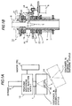
- the removing and disposing apparatus 20 for the needles is basically constituted of the removing mechanism 10 equipped with the motor 6 etc., into an upper entrance of which the syringe 9 is inserted during the removal of the mounted needle 8, and of the disposing container 11 for storing the removed needles 8, which drops downwards being guided by the cylinder 1.
- the container 11 includes the lid 14, which is tentatively fixed through a flexible sheet 15a having an end extending thereof a tongue end-shaped tab for pull-off or the fixing plate 15 for tentatively fixing on the bottom space 13a.
- the lid 14 is taken off from the plate 15 to hermetically seal the container 11 by closing the incoming and outgoing entrance 12 of the needles.
- the removing mechanism 10 for removing the needles rotatably supports the cylinder 1 through an uppermost bearing 1b embedded in a concave portion formed on a rear surface of an insertion frame 19 for receiving the syringe 9 denoted by a hatching of slanting solid lines, which is secured by means of screws to the main case 21 of the remover 10 represented by doubly dotted lines on an uppermost of FIG.1B.
- the cylinder 1 On an outer space corresponding to a lowest edge of the stopping position "a" of the syringe 9, the cylinder 1 rotatably supports the disk 2 through the bearing 1a, which is driven by a gear 6a attached to the motor 6.
- the braking load 5 formed of, for instance, a compression spring is attached being wound.
- the cylinder 1 holds a lower end of the spring while a supporting plate 22 of the removing mechanism 10, in which the thrust bearing 1c for supporting the cylinder 1 is embedded, receives a pressure of the spring through a receiving plate connected with an upper end of the spring.
- the main case 21 of the remover 10 or a rear surface of the disk 2 can herein receive the spring pressure while another brake can be attached to the remover 10 or the disk 2 to apply another pressure to the cylinder 1 on the contrary.
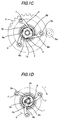
- the arms 3 are rotatably supported with their supported ends 3a around the supporting pins 7, which are aligned so as to form an equiangular polygon along the circle b drawn coaxially on the disk 2.
- the oblong-shaped holes 4, of which number and positioning correspond to those of the arms 3, are formed on the wall surface of the cylinder 1 at a height level of the stopping position "a" so that horizontal lengths of the holes 4 become longer than vertical lengths of the holes 4.
- Shapes of the holes 4 depend somewhat on cross-sectional shapes of the arm 3 so that differently shaped holes can be adoptable when arms having particularly shaped cross-sections are used, for instance, to raise a rigidity or to reduce a weight so long as the holes 4 are aligned so as to form an almost equiangular polygon on a cross-sectional plane of the cylinder 1.
- the free ends 3b of arms 3 are individually intruded through the corresponding holes 4 while the serrated edges 3c are formed on the free ends 3b so that the serrated edges 3c orient internally.
- the serrated edges 3c are replaceable with surfaces having other shapes including a zigzag-formed surface so long as they can grasp tightly the needle holder 8b.
- a corner shape and a plurality of small bumps which enable the container 11 to connect itself with the main case 21 of the removing mechanism 10, are provided on an upper side wall of the container 11 for disposing the removed needles.
- the incoming entrance 12, of which inner diameter can accept an insertion of a lower end of the hollow cylinder 1 from a direction indicated by a broad arrow shown in FIG.3A when the apparatus 20 is assembled is provided on an upper surface of the container 11.
- the conical form 13 such as a circular cone or a pyramid is formed inside the container 11.
- a partition wall having an appropriate height from the conical form 13, which separates an inner space substantially equally into a left and a right hand sides, can be supplied on an arbitrary position to prevent a movement of the stored needles to be disposed later.
- the lid 14 is formed so as to be fitted into the incoming and outgoing entrance hole 12.
- an upper part of the lid 14 is formed so as to have an appropriately larger diameter than that of the entrance 12, of which longitudinal cross-section is substantially a circular arc.
- a circular groove is formed just below the arc so as to be capable of fitting in the entrance 12.
- a lower projection having a slightly larger diameter than that of the groove is formed below the groove to enable to close the container 11 when the lid is fixed into the entrance 12.
- the tentative fixing plate 15 stacked with a flexible sheet 15a formed of such as a soft plastic resin polymer having an end extending thereof a tongue-end shaped-tab is herein attached to the lid 14.
- External shape and size of the fixing plate 15 are formed so that the plate 15 can be temporarily fixed by small bumps formed on a rear surface of the conical form 13 when it is pushed into the rear space 13a.
- Power supply for driving the motor 6 is applied from electric terminals 18 for connecting power supply lines while operational controls of the motor 6 are managed by output signals produced from a control circuit board 17.
- a snapswitch for switching the power supply circuit between a closed state and an open state can be provided externally near at hand for convenience, a power input socket being connected with the terminal 18, though the switch is unshown in the figures.
- the power supply is also applicable from a built-in battery equipped in the main case 21.
- the braking load 5 which is herein fixed to the cylinder 1 and gives a pressure on the plate 22 to suppress the free rotation of the cylinder 1 during operation of the remover 10, is replaceable with a plumb bob having an appropriate weight instead of afore-mentioned pressure induced by the coil spring.
- the power necessary for gripping the needle holder 8b with the serrated edges 3c before loosening the meshed screw 8a requires of the cylinder 1 a comparatively larger resistive force with respect to rotation, which can be afforded by a static friction coefficient of the braking load 5.
- the container 11 for disposing the needles is herein a disposable-type container, which is to be closed with the lid 14 and incinerated after accepting an appropriate volume of the removed needles. No lid can be pulled off again by bare hands anymore so long as the lid 14 is fitted directly without inserting the tentative fixing plate 15 or the flexible sheet 15a. If a recycle-type container is used, the fixing plate 15 or the flexible sheet 15a is usable between the lid and the entrance 12. Then an empty container is newly assembled with the main case 21 of the remover 10.
- the positioning, on which the lid 14 is tentatively fixed through the tentative fixing plate 15 or the flexible sheet 15a having the end extending thereof the tongue-end shaped-tab for pulling-off formed of such as a soft plastic resin film, is not necessarily limited to the vacant space 13a for space saving on the rear surface of the conical form 13.
- Those components can be tentatively fixed even on a front surface of the container 11 if afore-mentioned corner shape and small bumps for connecting the container 11 with the main case 21 of the remover 10 are well designed and formed to provide an enough vacant space between the remover 10 and the container 11. Removing the lid 14 tentatively attached to the front surface enables a faster closing and a less vibration of the container during encapsulation, compared with that tentatively attached to the rear space 13a.
- Materials in use for the components constituting the apparatus 20 of the present invention are preferably to be plastic resins selected from synthetic plastic resins including ABS (acrylonitrile-butadien-stylene) co-polymerized resin, polypropylene resin and polyethylene resin. They are also preferably to be materials selected from wooden materials and light metals, of which surfaces have been subjected to an appropriate surface treatment. Materials in use for the hollow cylinder 1 is preferably to be stainless steels because contacts of the used needles frequently take place.
- the electric motor 6 is preferably a motor in use for DC (direct current) 12 V (volts) and, for instance in use for removing the needles having diameters no greater than 8 mm (millimeters), has preferably an output power about 5 W (watt).
- a motor equipped with a deceleration mechanism is usable meanwhile a mechanical system which intervenes reduction gears inbetween is also available.
- the control of the rotational speed of the motor is also attainable either by an electronic method, wherein a frequency of the power supply is converted, or by an electric method, wherein a voltage of the power supply is varied.
- a simplest way to start and stop the rotation of the motor 6 is obtainable by programming elapsing times on a time switch.
- the power supply for the motor also can be turned off when an operational load turns insensible after an elapse of a certain period of time.
- the same time schedule can be repeatedly programmed again on the time switch.
- a supply power control of the motor 6 can be done by sensing a number of revolutions of the motor because if an unscrewing operation is assuredly performed being adjusted to a number of threaded ridges, the threaded portion 8a of the needle 8 can be just removed from the syringe 9.
- the control of rotating the motor is also attainable by use of a sensor, which can detect a falling down status of the removed needle.
- the motor can be stopped with a few reverse rotations for a time when the load during the operation turns assuredly insensible.
- the removing mechanism 10 in the apparatus 20 of the present embodiment constituted as mentioned above works its functions just as an operational sequence shown in FIG.4.
- the syringe 9 equipped with the needle 8 When the syringe 9 equipped with the needle 8 is manually inserted from the upper entrance of the main case 21 at Seq (Sequence) (1), the sensor detects the insertion of the syringe 9 and turns the microswitch 16 on to introduce the electric power at Seq (2).
- the circuitry is interconnected so that the motor 6 continues rotation for t seconds, which has been programmed on the timer, if the motor 6 starts to rotate.
- the output power of the motor 6 then rotates through the gear 6a the rotating disk 2 in a clockwise direction denoted by a curved arrow r shown in FIG.1D.
- This begins to drive the arms 3 for traversing at Seq (2), of which supported ends 3a are rotatably supported on the disk 2 around the supporting pin 7.
- the free ends 3b of the arms 3, which at first are located adjacently to an inside wall of the cylinder 1, are moved inwardly until the serrated edges 3c touch the outside surface 8b of the threaded portion 8a at Seq (3), utilizing the side edges 4a of the holes 4 as the flucra of the levers.
- the bearing 1a works further to fasten the grip of the serrated edge 3c, which grasps the outer surface 8b of the screw portion 8a.
- the arms 3 begin rotating the needle 8 by overcoming a resistive force formed of the braking load 5, which is attached to the cylinder 1 and presses the supporting plate 22 of the remover 10, simultaneously rotating the cylinder 1.
- a delay in rotation of the cylinder 1 induced by the braking load 5 maintains the gripping force of the serrated edges 3c during unscrewing the needle 8.
- a rotation of the motor 6 at least at 360 degrees in an opposite direction represented by broken lines shown in FIG.4 moves the free ends 3b outwardly toward the inside wall of the cylinder 1 till Seq (6) by utilizing another side edges 4b of the openings 4 as flucra of levers. Between Seqs (5) and (6), the removed needle falls down from the free ends 3b of arms 3 into the container 11 for storing and disposing.
- the removing mechanism of the apparatus according to the present invention is further simplified than those up to now and guarantees a stable gripping force and a strong unscrewing power of the needle only by a unidirectional rotation of the motor, employing the plurality of the elongated arms and the openings having an appropriate shape formed on the cylinder surface for guiding the arms.
- the disposing container of the apparatus according to the present invention is the cartridge-type disposable container, which can store the wasted needles at a substantially uniformly distributed status on the bottom and be incinerated at an enclosed status with the lid.
- the apparatus for removing the needles and the disposing the same according to the present invention which is essentially constituted in combination of the removing mechanism mentioned above and of the container similarly mentioned above, has another advantages in marketability such as an easy handling and an economical equipment price beside advantages in safety and in environmental hygiene such as an isolability of the threaded needles, which have been thought difficult to be removed, from finger tips throughout all handling process steps from the automated removal to the disposing treatment just prior to the incineration and a substantial elimination of polluting the environment.
- the apparatus according to the present invention not only can reduce dangers for inducing probability of the medical accidents but also can give large technological and managerial impacts concerning the industrial hygienics upon an environmental improvement of medical care sites.
Landscapes
- Health & Medical Sciences (AREA)
- Engineering & Computer Science (AREA)
- Heart & Thoracic Surgery (AREA)
- Vascular Medicine (AREA)
- Anesthesiology (AREA)
- Biomedical Technology (AREA)
- Environmental & Geological Engineering (AREA)
- Hematology (AREA)
- Life Sciences & Earth Sciences (AREA)
- Animal Behavior & Ethology (AREA)
- General Health & Medical Sciences (AREA)
- Public Health (AREA)
- Veterinary Medicine (AREA)
- Accommodation For Nursing Or Treatment Tables (AREA)
- Infusion, Injection, And Reservoir Apparatuses (AREA)
Applications Claiming Priority (2)
| Application Number | Priority Date | Filing Date | Title |
|---|---|---|---|
| JP299817/96 | 1996-10-25 | ||
| JP8299817A JPH10127709A (ja) | 1996-10-25 | 1996-10-25 | 注射針脱離処分装置 |
Publications (2)
| Publication Number | Publication Date |
|---|---|
| EP0838228A2 true EP0838228A2 (fr) | 1998-04-29 |
| EP0838228A3 EP0838228A3 (fr) | 1998-05-13 |
Family
ID=17877290
Family Applications (1)
| Application Number | Title | Priority Date | Filing Date |
|---|---|---|---|
| EP97117938A Withdrawn EP0838228A3 (fr) | 1996-10-25 | 1997-10-16 | Dispositif de séparation d'aiguilles et de leur mise au rebut |
Country Status (3)
| Country | Link |
|---|---|
| EP (1) | EP0838228A3 (fr) |
| JP (1) | JPH10127709A (fr) |
| TW (1) | TW354490U (fr) |
Cited By (11)
| Publication number | Priority date | Publication date | Assignee | Title |
|---|---|---|---|---|
| WO1999006090A1 (fr) * | 1997-08-01 | 1999-02-11 | Rudolf Becker | Dispositif d'elimination pour les canules des seringues d'injection |
| GB2376892A (en) * | 2001-06-28 | 2002-12-31 | Stephen Francis Gerard Cooley | Medical needle removal device |
| WO2004047896A1 (fr) * | 2002-11-25 | 2004-06-10 | Tecpharma Licensing Ag | Dispositif de maintien temporaire d'une coiffe de protection d'aiguille d'un dispositif d'injection |
| EP1614439A1 (fr) | 2004-06-19 | 2006-01-11 | Stephen Francis Gerald Cooley | Dispositif pour extraction des aiguilles |
| CN103894970A (zh) * | 2012-12-24 | 2014-07-02 | 健康机器人技术有限公司 | 用于移除注射器的针的设备 |
| FR3039070A1 (fr) * | 2015-07-22 | 2017-01-27 | Aurelien Rous | Collecteur pour seringues permettant la separation de l'aiguille du corps de la seringue |
| CN109453445A (zh) * | 2018-12-19 | 2019-03-12 | 河南科技大学第附属医院 | 一种具有拆针器的医用利器盒 |
| US10258746B2 (en) | 2014-03-25 | 2019-04-16 | Inventive Medical Devices, Llc | Apparatus and method of automatically removing a needle from a hub |
| NL2021051B1 (en) * | 2018-06-04 | 2019-12-11 | Plakgoot Holding B V | Device for rotating an object |
| CN111938710A (zh) * | 2020-08-12 | 2020-11-17 | 王铖 | 一种自动更换收液器的妇科用子宫取液装置 |
| CN121370611A (zh) * | 2025-12-25 | 2026-01-23 | 上海市同仁医院 | 一种超声针灸治疗装置 |
Families Citing this family (3)
| Publication number | Priority date | Publication date | Assignee | Title |
|---|---|---|---|---|
| KR100350634B1 (ko) * | 2000-03-03 | 2002-08-30 | 인창전자주식회사 | 주사바늘 분리기 |
| EP1598043A4 (fr) * | 2003-02-27 | 2008-05-28 | Showa Pharm Chem Ind | Dispositif d'enlevement d'aiguille de seringue pour seringues de type a cartouche dentaires |
| JP6346025B2 (ja) * | 2014-07-31 | 2018-06-20 | ニプロ株式会社 | 注射針廃棄用容器 |
Family Cites Families (3)
| Publication number | Priority date | Publication date | Assignee | Title |
|---|---|---|---|---|
| JPH05253300A (ja) * | 1992-03-16 | 1993-10-05 | Fujisawa Pharmaceut Co Ltd | 電動式注射針離脱装置 |
| FR2714836B1 (fr) * | 1994-01-11 | 1996-03-29 | Henry Abrard | Dispositif pour extraire automatiquement l'aiguille d'une seringue à usage médical ou paramédical et, notamment à usage dentaire. |
| DE29608141U1 (de) * | 1996-05-04 | 1996-08-01 | Kann, Hildegard van, 47798 Krefeld | Entsorgungsgerät zur Entfernung gebrauchter Kanülen, insbesondere Einwegkanülen |
-
1996
- 1996-10-25 JP JP8299817A patent/JPH10127709A/ja active Pending
-
1997
- 1997-09-25 TW TW086216349U patent/TW354490U/zh unknown
- 1997-10-16 EP EP97117938A patent/EP0838228A3/fr not_active Withdrawn
Cited By (16)
| Publication number | Priority date | Publication date | Assignee | Title |
|---|---|---|---|---|
| WO1999006090A1 (fr) * | 1997-08-01 | 1999-02-11 | Rudolf Becker | Dispositif d'elimination pour les canules des seringues d'injection |
| GB2376892A (en) * | 2001-06-28 | 2002-12-31 | Stephen Francis Gerard Cooley | Medical needle removal device |
| GB2376892B (en) * | 2001-06-28 | 2004-07-07 | Stephen Francis Gerard Cooley | Medical needle removal device |
| WO2004047896A1 (fr) * | 2002-11-25 | 2004-06-10 | Tecpharma Licensing Ag | Dispositif de maintien temporaire d'une coiffe de protection d'aiguille d'un dispositif d'injection |
| US7370759B2 (en) | 2002-11-25 | 2008-05-13 | Tecpharma Licensing Ag | Device for temporarily retaining a protective needle cap of an injection apparatus |
| EP1614439A1 (fr) | 2004-06-19 | 2006-01-11 | Stephen Francis Gerald Cooley | Dispositif pour extraction des aiguilles |
| CN103894970A (zh) * | 2012-12-24 | 2014-07-02 | 健康机器人技术有限公司 | 用于移除注射器的针的设备 |
| US10258746B2 (en) | 2014-03-25 | 2019-04-16 | Inventive Medical Devices, Llc | Apparatus and method of automatically removing a needle from a hub |
| FR3039070A1 (fr) * | 2015-07-22 | 2017-01-27 | Aurelien Rous | Collecteur pour seringues permettant la separation de l'aiguille du corps de la seringue |
| US11992664B2 (en) | 2018-06-04 | 2024-05-28 | Sharpfield Holding B.V. | Device for rotating an object |
| NL2021051B1 (en) * | 2018-06-04 | 2019-12-11 | Plakgoot Holding B V | Device for rotating an object |
| WO2019235917A1 (fr) * | 2018-06-04 | 2019-12-12 | Plakgoot Holding B.V. | Dispositif pour faire tourner un objet |
| CN109453445A (zh) * | 2018-12-19 | 2019-03-12 | 河南科技大学第附属医院 | 一种具有拆针器的医用利器盒 |
| CN109453445B (zh) * | 2018-12-19 | 2020-11-13 | 河南科技大学第一附属医院 | 一种具有拆针器的医用利器盒 |
| CN111938710A (zh) * | 2020-08-12 | 2020-11-17 | 王铖 | 一种自动更换收液器的妇科用子宫取液装置 |
| CN121370611A (zh) * | 2025-12-25 | 2026-01-23 | 上海市同仁医院 | 一种超声针灸治疗装置 |
Also Published As
| Publication number | Publication date |
|---|---|
| TW354490U (en) | 1999-03-11 |
| JPH10127709A (ja) | 1998-05-19 |
| EP0838228A3 (fr) | 1998-05-13 |
Similar Documents
| Publication | Publication Date | Title |
|---|---|---|
| EP0838228A2 (fr) | Dispositif de séparation d'aiguilles et de leur mise au rebut | |
| US8201323B2 (en) | Hypodermic needle extraction and disposal system and device | |
| JP4122367B1 (ja) | ゴミ箱 | |
| US4862573A (en) | Medical sampling needle removal and disposal device | |
| US7594376B2 (en) | Automated twist diaper disposal apparatus | |
| US4807344A (en) | Medical sampling needle removal and disposal device | |
| CN104973363B (zh) | 智能垃圾桶 | |
| EP1925570B1 (fr) | Réceptacle destiné à un contaminant | |
| WO2010113388A1 (fr) | Récipient pour collecter des aiguilles devant être jetées et élément de collecte d'aiguilles devant être jetées | |
| EP1614439B1 (fr) | Dispositif pour extraction des aiguilles | |
| EP3920978B1 (fr) | Système de nettoyage et/ou de désinfection d'un tube creux, notamment une béquille de poignée de porte | |
| WO1988000067A1 (fr) | Recipients | |
| US6202843B1 (en) | Cooperative medical sampling and needle removal devices | |
| US5531323A (en) | Cooperative medical sampling and needle removal devices | |
| JPH05253300A (ja) | 電動式注射針離脱装置 | |
| RU2391282C2 (ru) | Мусорный ящик, имеющий уплотняющее средство | |
| JPH0663136A (ja) | 注射針とハブとの分離装置 | |
| US20080061184A1 (en) | Line Collection Apparatus | |
| NL1006153C2 (nl) | Apparaat voor het losdraaien van gebruikte medische naalden. | |
| JPH035823B2 (fr) | ||
| US5702366A (en) | Safety fluid collector | |
| CN221458758U (zh) | 一种具有压缩功能的医疗废弃垃圾桶 | |
| JP3019500U (ja) | 医療用針の取り外し装置 | |
| BE1007352A3 (nl) | Inrichting voor het losmaken van gebruikte injektienaalden. | |
| CN215466976U (zh) | 一种耳鼻喉科用医疗废弃物处理装置 |
Legal Events
| Date | Code | Title | Description |
|---|---|---|---|
| PUAI | Public reference made under article 153(3) epc to a published international application that has entered the european phase |
Free format text: ORIGINAL CODE: 0009012 |
|
| PUAL | Search report despatched |
Free format text: ORIGINAL CODE: 0009013 |
|
| AK | Designated contracting states |
Kind code of ref document: A2 Designated state(s): DE ES FR GB IT NL |
|
| AK | Designated contracting states |
Kind code of ref document: A3 Designated state(s): AT BE CH DE DK ES FI FR GB GR IE IT LI LU MC NL PT SE |
|
| 17P | Request for examination filed |
Effective date: 19981020 |
|
| AKX | Designation fees paid |
Free format text: DE ES FR GB IT NL |
|
| RBV | Designated contracting states (corrected) |
Designated state(s): DE ES FR GB IT NL |
|
| STAA | Information on the status of an ep patent application or granted ep patent |
Free format text: STATUS: THE APPLICATION IS DEEMED TO BE WITHDRAWN |
|
| 18D | Application deemed to be withdrawn |
Effective date: 20000503 |