EP0838234A2 - Implantierbares Stimulationsgerät - Google Patents
Implantierbares Stimulationsgerät Download PDFInfo
- Publication number
- EP0838234A2 EP0838234A2 EP97250320A EP97250320A EP0838234A2 EP 0838234 A2 EP0838234 A2 EP 0838234A2 EP 97250320 A EP97250320 A EP 97250320A EP 97250320 A EP97250320 A EP 97250320A EP 0838234 A2 EP0838234 A2 EP 0838234A2
- Authority
- EP
- European Patent Office
- Prior art keywords
- heart
- stimulation device
- stimulation
- blood flow
- blood
- Prior art date
- Legal status (The legal status is an assumption and is not a legal conclusion. Google has not performed a legal analysis and makes no representation as to the accuracy of the status listed.)
- Granted
Links
Images


Classifications
-
- A—HUMAN NECESSITIES
- A61—MEDICAL OR VETERINARY SCIENCE; HYGIENE
- A61N—ELECTROTHERAPY; MAGNETOTHERAPY; RADIATION THERAPY; ULTRASOUND THERAPY
- A61N1/00—Electrotherapy; Circuits therefor
- A61N1/18—Applying electric currents by contact electrodes
- A61N1/32—Applying electric currents by contact electrodes alternating or intermittent currents
- A61N1/36—Applying electric currents by contact electrodes alternating or intermittent currents for stimulation
- A61N1/362—Heart stimulators
- A61N1/3621—Heart stimulators for treating or preventing abnormally high heart rate
- A61N1/3622—Heart stimulators for treating or preventing abnormally high heart rate comprising two or more electrodes co-operating with different heart regions
-
- A—HUMAN NECESSITIES
- A61—MEDICAL OR VETERINARY SCIENCE; HYGIENE
- A61N—ELECTROTHERAPY; MAGNETOTHERAPY; RADIATION THERAPY; ULTRASOUND THERAPY
- A61N1/00—Electrotherapy; Circuits therefor
- A61N1/18—Applying electric currents by contact electrodes
- A61N1/32—Applying electric currents by contact electrodes alternating or intermittent currents
- A61N1/36—Applying electric currents by contact electrodes alternating or intermittent currents for stimulation
- A61N1/362—Heart stimulators
- A61N1/365—Heart stimulators controlled by a physiological parameter, e.g. heart potential
- A61N1/36514—Heart stimulators controlled by a physiological parameter, e.g. heart potential controlled by a physiological quantity other than heart potential, e.g. blood pressure
-
- A—HUMAN NECESSITIES
- A61—MEDICAL OR VETERINARY SCIENCE; HYGIENE
- A61N—ELECTROTHERAPY; MAGNETOTHERAPY; RADIATION THERAPY; ULTRASOUND THERAPY
- A61N1/00—Electrotherapy; Circuits therefor
- A61N1/18—Applying electric currents by contact electrodes
- A61N1/32—Applying electric currents by contact electrodes alternating or intermittent currents
- A61N1/36—Applying electric currents by contact electrodes alternating or intermittent currents for stimulation
- A61N1/362—Heart stimulators
- A61N1/365—Heart stimulators controlled by a physiological parameter, e.g. heart potential
- A61N1/36514—Heart stimulators controlled by a physiological parameter, e.g. heart potential controlled by a physiological quantity other than heart potential, e.g. blood pressure
- A61N1/36571—Heart stimulators controlled by a physiological parameter, e.g. heart potential controlled by a physiological quantity other than heart potential, e.g. blood pressure controlled by blood flow rate, e.g. blood velocity or cardiac output
Definitions
- the invention relates to an implantable stimulation device according to the preamble of claim 1.
- implantable cardioversion devices also as Defibrillators referred to - use that over a in usually located endocardially in the ventricle Capture spontaneous cardiac signals and upon detection of Ventricular fibrillation or flutter an energetic Current pulse - hereinafter referred to as defibrillation pulse - give to the heart because of its strength to excite and depolarize almost all of them Leads to areas of the heart so that the arrhythmia state ends and the normal sinus rhythm regains control can take over the heartbeat.
- Heart signals are subject to a variety of interference options.
- the amplitude of the spontaneous cardiac signals can be temporal Fluctuations, for example, in the day-night rhythm subject to reliable detection of arrhythmic Complicate heart conditions.
- electromagnetic interference signals incorrectly as intracardiac ECG signals are recognized.
- spontaneous atrial cardiac signals become electrical crosstalk the ventricle so that a relatively harmless Atrial fibrillation is incorrectly recognized as ventricular fibrillation and triggers a defibrillation pulse, although none critical condition of the patient is present.
- the known Defibrillators is the reliability of the detection of arrhythmic heart conditions is unsatisfactory.
- pacemakers for treating one disturbed conduction from the atrium to the ventricle.
- Such pacemakers usually record via a spontaneous atrial electrode located endocardially in the atrium Actions and give each at a predetermined AV transition time delayed after any spontaneous atrial Action a stimulation pulse to the ventricle.
- the Delay in ventricular pacing after each atrial Action is required to ensure optimal chamber filling before the contraction as a prerequisite for a good one Allow pumping power of the heart, being the optimal Value of the AV transition time individually for the respective Pacemaker carrier and is also temporal May be subject to fluctuations.
- the invention is therefore based on the object of an implantable To create stimulation device in which the control the pulse delivery to end arrhythmic dysfunctions better adapted to the needs of the patient is.
- the invention is based on an implantable Stimulation device according to the preamble of claim 1, solved by the characterizing features of claim 1.
- the invention includes technical teaching, pulse delivery in a generic implantable stimulation device depending on the pumping power of the heart to control by pumping the heart through a hemodynamic sensor is detected in or on a blood vessel detects the blood flow.
- a hemodynamic Sensor in the vena cava or pulmonary artery to arrange.
- stimulation device in the following includes in particular Cardioverters and defibrillators, but also modern ones multifunctional pacemaker, the inventive Principle in the treatment of certain Tachycardia states as well as herbal fibrillation and cardiac arrest if necessary.
- the hemodynamic sensor can measure the flow rate of the blood quantify or in special Applications only a yes / no statement regarding the blood flow deliver.
- the hemodynamic Sensor a heatable resistance element with a temperature-dependent electrical resistance, which for heat dissipation depending on the amount of blood flow Blood vessel is arranged to make thermal contact.
- the heating the resistance element can, for example, be electrical take place by the resistance element with a Voltage source is connected, so that the resistance element heated up by the ohmic losses inside.
- the temperature of the resistance element can then be in simply from the electrical resistance of the resistance element calculate if the temperature dependence of the electrical resistance element is known.
- the electric one Resistance of the resistance element results accordingly Ohm's law from the applied heating voltage and the heating current flowing through the resistance element.
- the electrical resistance of the resistance element thus reflects the flow rate of the blood in the respective blood vessel and thereby enables an assessment the heart pumping capacity. It is particularly advantageous it, the resistance element with an amplifier on one Integrate chip, resulting in a small size of the Sensor can be realized.
- the hemodynamic is detected Sensor, however, the impedance of the blood, whereby the surprising finding that the Impedance of the blood, among other things, from the flow rate depends.
- the hemodynamic sensor therefore shows in this variant of the invention on two measuring electrodes are arranged in the blood vessel and thus an impedance measurement of the blood.
- the two measuring electrodes are included a signal generator integrated in the stimulation device connected, an electrical test signal for impedance measurement generated that given to the two measuring electrodes becomes.
- the stimulation device integrated ammeter the current flow over the measured two measuring electrodes, which is then the calculation the impedance of the blood allows the flow rate of the blood and thus the pumping power of the Heart reflects.
- the two measuring electrodes integrated into the catheter which for Placement of the stimulation electrode inserted into the heart becomes.
- the hemodynamic sensor By integrating the hemodynamic sensor into the stimulation device according to the invention can be the catheter implant advantageously without additional effort because the catheter for the placement of the stimulation electrode anyway is required.
- the two measuring electrodes are located preferably in the wall of the catheter axially spaced from each other at a position which lies outside the heart when implanted.
- the two measuring electrodes can flow in the blood vessel one after the other or side by side across the direction of the river be arranged to measure the anisotropy of the impedance of the blood, which stems from the fact that the erythrocytes in a blood flow sometimes in one Align preferred direction.
- the control of the pulse delivery takes place here not only depending on the measured Blood flow, but also depending on the spontaneous Heart signals and can thus better meet the needs adapt to the patient's physical condition from the control unit due to the more diverse diagnostic information can be better recognized.
- interference signals can be suppressed in this way, which only relate to a single input variable impact. For example, it is conceivable that the measured spontaneous heart signals through electromagnetic interference signals be falsified while the measured pump power is largely unadulterated. Through the evaluation different signals offers the possibility of one mutual plausibility check between the different signals to suppress interference.
- the control unit points to the evaluation of the spontaneous heart signals in a variant of the invention, a signal analysis unit on the input side with the for the detection of spontaneous cardiac signal serving electrode is connected and judged from the measured spontaneous cardiac signals whether you have a heart problem.
- the signal analysis unit making a detection tachycardia or arrhythmic heart problems, like ventricular fibrillation, and when detected such a cardiac dysfunction Control signal generated.
- the delivery of defibrillation pulses does not only depend on the spontaneous heart signals, but also depends on the heart pumping performance influenced by the hemodynamic sensor is measured.
- the input signals is suitable here also in the implementation of the invention in other stimulation devices preferably a logic unit, which is also the Inclusion of additional diagnostic parameters enables how for example the physical one detected by an activity sensor Activity or minute volume of breath by Measurement of the intracardiac impedance can be determined.
- the hemodynamic sensor is not permanently closed operate to the energy consumption when operating the stimulation device to lower, which is particularly advantageous then is when the hemodynamic sensor - as described above - Has a heatable resistance element, because the operation of the hemodynamic sensor in this case with is associated with a relatively high energy consumption.
- the activation The hemodynamic sensor is used in this variant the invention by a controllable switching element, the control of the switching element for example time or remote controlled via a telemetry receiver.
- it is particularly advantageous activate the hemodynamic sensor if the evaluation of spontaneous cardiac signals an arrhythmic Heart condition.
- the measurement result of the hemodynamic Sensors then enables a plausibility check and thus prevents the delivery of a contraindicated Defibrillation pulse.
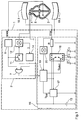
- FIG. 1 The implantable shown in Figure 1 as a block diagram Defibrillator 1 enables automatic detection and termination of an arrhythmic heart condition Delivery of a high-energy defibrillation pulse, the due to its strength to excitement and depolarization leads to almost all areas of the heart, so that the arrhythmia is ended and the normal sinus rhythm again can take control of the heartbeat.
- Control unit 2 on the input side for assessing the cardiac function on the one hand with an endocardial in the ventricle arranged electrode 3 and the other with one in the Vena Cava arranged hemodynamic sensor 4 connected whose structure is shown in detail in Figure 3a.
- the electrode 3 enables the detection more spontaneously Heart signals and the detection of an arrhythmic heart condition, while the hemodynamic sensor 4 the flow rate of the blood and thus an assessment the pumping power of the heart 5 allowed.
- the control of the Provides impulses through different input signals different advantages.
- the control unit 2 due to the different diagnostic input signals a more accurate picture of the heart function so that the Control of pulse delivery better to the needs of the Patients can be adjusted.
- Such a mutual plausibility check of the two input signals increases the Reliability in the detection of arrhythmic cardiac dysfunction and largely avoids false detections and contraindicated defibrillation pulses.
- the Control unit 2 has a signal analysis unit 6 on the input side to record the spontaneous heart signals with the Endocardially arranged electrode 3 is connected. At a Detection of an arrhythmic heart condition produces the Signal analysis unit 6 with a corresponding control signal a logical HIGH level, which is used for further evaluation AND gate 7 is supplied.
- the hemodynamic Sensor 4 is therefore in normal operation of the defibrillator 1 switched off to save energy and is only at one Detection of an arrhythmic heart condition by the signal analysis unit 6 turned on, based on the measured Perform a plausibility check and a contraindicated delivery of a defibrillation pulse to prevent.
- the hemodynamic sensor 4 consists - as well as of figure 3a can be seen - essentially from a resistance element 8 and is located in the vena cava. To an electric Contact with the flowing blood or the wall of the vessel to prevent the resistance element 8 with a electrically insulating, but with good thermal conductivity Pour mass 9 through which the leads 10 are passed are.
- Figure 4 shows an example the pulsating course of the electric current through the resistance element 8 for a normal heart rate.
- the fluctuations in the current flow are clear recognize that reflect the heart rhythm.
- the output signal the current measuring device 12 is therefore one Signal analysis unit 14 supplied, the pump power from it of the heart 5 and this value with a compares the predetermined limit.
- the Pump power below the specified limit takes the Signal analysis unit 14 as an arrhythmic cause Heart state and therefore generates a corresponding output side Control signal with a HIGH level, the following fed to the AND gate 7 for further processing becomes.
- the AND gate 7 is used to trigger the pulse generator 15 for delivering a defibrillation pulse in the event of a arrhythmic heart condition, due to the AND link only then a defibrillation pulse is given, if both the evaluation of the spontaneous cardiac signals as also the evaluation of the pumping power of the heart 5 ventricular fibrillation or flutter.
- a defibrillation pulse is given, if both the evaluation of the spontaneous cardiac signals as also the evaluation of the pumping power of the heart 5 ventricular fibrillation or flutter.
- This plausibility check becomes a contraindicated delivery of a defibrillation pulse with a disturbed signal acquisition prevented from the heart 5.
- this will prevents a relative in electrical crosstalk harmless atrial fibrillation from the atrium to the ventricle incorrectly detected ventricular fibrillation and a defibrillation pulse which is contraindicated in this case would.
- the defibrillation pulses are generated by the pulse generator 15, which is controlled by the AND gate 7 of the control unit 2 and, in the presence of an arrhythmic cardiac state, first one of the buffer capacitors C 1 , C 2 , C 3 during a charging phase by the switching means 16 with the voltage regulating circuit 17 connects, whereby the buffer capacitor is charged.
- the voltage control circuit 17 is connected on the input side to the battery 13 for energy supply and provides an output voltage, the level of which can be set virtually continuously between 560 V and 800 V.
- the selected buffer capacitor C 1 , C 2 or C 3 is then separated from the voltage control circuit 17 by the switching means 16 and connected to the stimulation electrode 18.1 via the output resistor R, so that the buffer capacitor C 1 , C 2 or C 3 discharges via the heart 5 and the ground electrode 18.2 and emits a defibrillation pulse.
- the stimulation electrode 18.1 and the ground electrode 18.2 - in contrast to the detection electrode 3 - have a large area in order to prevent tissue burns or damage when the high-energy defibrillation pulses are delivered.
- control unit 19 The time control of the switching means 16 for charging the buffer capacitor or for delivering the defibrillation pulse is carried out here by the control unit 19.
- control unit 19 also enables the defibrillation energy to be adapted to the individual defibrillation threshold of the patient, either by the Voltage control circuit 17 provided charging voltage or the capacitance of the buffer capacitor is changed.
- the control unit 19 is therefore connected on the output side to the voltage control circuit 17 for setting the charging voltage and to the switching means 16 for selecting one of the buffer capacitors C 1 , C 2 , C 3 .
- the buffer capacitor is switched by the switching means 16 again separated from the stimulation electrode 18.1, which ends the defibrillation pulse.
- the buffer capacitor C 1 , C 2 or C 3 is disconnected from the stimulation electrode 18.1 in good time in order to terminate a defibrillation pulse before the capacitor voltage falls below the rheobase value due to the discharge, since a further discharge does not have a defibrillating effect , but can at best initiate refibrillation.
- the buffer capacitor C 1 , C 1 or C 3 it is desirable to discharge the buffer capacitor C 1 , C 1 or C 3 as completely as possible, since the residual charge remaining on the buffer capacitor C 1 , C 2 or C 3 after a defibrillation pulse cannot be used or can only be used incompletely and thus the Efficiency of the defibrillator 1 is reduced, which is defined as the ratio of stored energy to energy output.
- the defibrillator 1 therefore continuously measures the stimulation voltage during the delivery of a defibrillation pulse and terminates the defibrillation pulse when the rheobase voltage is undershot.
- the defibrillator 1 has a voltage measuring device 20 which is connected on the input side to the connection for the stimulation electrode 18.1 and on the output side to the control unit 19 in order to be able to measure the defibrillation voltage and, if necessary, to terminate the defibrillation pulse.
- the control unit 19 When the rheobase voltage is reached, the control unit 19 then generates a control signal for the switching means 16, which then separate the buffer capacitor C 1 , C 2 or C 3 from the stimulation electrode 18.1 and thus terminate the defibrillation pulse.
- this advantageously prevents a defibrillation pulse from having a refibrillating effect when the defibrillation voltage drops below the rheobase voltage.
- this advantageously prevents a defibrillation pulse from having a refibrillating effect when the defibrillation voltage drops below the rheobase voltage.
- by continuously measuring the defibrillation voltage when discharging the buffer capacitor C 1 , C 2 or C 3 there is no need for a safety margin between the defibrillation voltage and the rheobase voltage, so that the buffer capacitor C 1 , C 2 or C 3 discharges to the rheobase voltage can be, which increases the battery life.
- FIG. 2 shows another embodiment of the invention a rate-adaptive two-chamber pacemaker 21 for the treatment of disturbed conduction from the atrium to the ventricle.
- the pacemaker shown detects 21 via an electrode 22 placed endocardially (in the atrium) spontaneous heart signals, initially an input amplifier 23 and then fed to a signal analysis unit 24 to detect spontaneous atrial action which occurs as a P-wave in the detected heart signals.
- a control signal which initializes the counter 25, the starting value of the counter 25 from the computing unit 26 is calculated from the activity signal ACT, generated by the piezoelectric acceleration sensor 27 and the physical activity of the pacemaker wearer reflects.
- the counter 25 With every clock pulse of the oscillator 28, the counter 25 then reduces its count to to zero, whereupon the counter 25 sends a control signal to the Pulse generator 29, which then outputs a stimulation pulse generated and fed to the atrium via the electrode 22.
- the pacemaker shown enables 21 stimulation of the ventricle, which in particular with a disturbed conduction from the atrium to the ventricle important is.
- the ventricle is stimulated here each delayed by a specified AV transition time after the previous spontaneous or stimulated atrial action to allow the ventricle to contract before contraction fill as completely as possible with blood in order to a given cardiac output as large as possible to reach.
- the counter 30 for timing the ventricle is therefore on the input side with the signal analysis unit 24 and the other with the counter 25 for the atrial timing connected to both spontaneous and an AV conduction time for a stimulated atrial action to start, with the starting value for the Counter 30 is stored in the memory element 31.
- the counter 30 With everyone Clock pulse of the oscillator 28 decrements the counter 30 then the count down to zero, whereupon a control signal is delivered to the pulse generator 32, which thereupon has a
- the stimulation pulse is generated and applied via the electrode 33 releases the ventricle.
- the ventricle is stimulated but not rigid after every atrial atrial action, but can be replaced by one during the AV transition period spontaneous ventricular action occurring inhibited will.
- the electrode 33 arranged in the ventricle is for this purpose with an input amplifier 34 and a downstream one Signal analysis unit 35 connected to a spontaneous Detect ventricular action in the sensed Cardiac signals appear as a QRS complex.
- the signal analysis unit On detection the signal analysis unit generates such a QRS complex 35 an inhibition signal supplied to the counter 30 which then aborts its counting process and thus also not stimulating a stimulation pulse.
- the pacemaker 21 enables automatic adjustment the AV transition time.
- the pacemaker 21 measures via a hemodynamic Sensor the flow rate of the blood in the Vena Cava 37 to assess the pumping power of the heart 36 to be able to.
- the hemodynamic sensor essentially exists from a resistance element arranged in the vena cava 38 with a temperature-dependent electrical resistance, that during a measurement process via the current measuring device 39 and the controllable switching element 40 with of the battery 41 is connected, whereby the resistance element 38 due to the ohmic losses in his Heated inside.
- the measurement of the flow rate through the resistance element 38 associated with additional power consumption is not permanent, but instead each at programmed times, e.g. with a time interval of a few hours.
- the illustrated Pacemaker 21 on another counter 42 the is also controlled by the oscillator 28 and each when a certain counter reading is reached Control signal generated, the controllable switching element 40th is supplied, whereupon the resistor element 38 connects to the battery 41 via the current measuring device 39.
- the temperature of the resistance element 38 then increases until there is a balance between the supplied and completely in the resistance element 38 Heat converted power on the one hand and by heat conduction and convection from the blood flowing past thermal performance on the other hand. Because the through Convection dissipated power at the flow rate blood increases, there is a dependency between the Temperature of the resistance element 38 and the flow rate of the blood. So at low flow speeds little heat dissipated by convection, so that to discharge the electrical energy supplied a relatively large temperature gradient on the resistance element 38 and thus a correspondingly high temperature is required is.
- the temperature of the resistance element 38 reflects the flow rate of the blood reflected and can be due to the temperature-dependent electrical Conductivity of the resistance element 38 in simple Way from the current flow through the resistance element 38 calculate.
- the output signal of the current measuring device 39 is therefore used as a measure of the flow rate of the computing unit 43 fed from it the cardiac output (HZV) calculated, which reflects the pump power.
- the computing unit 43 comprises a compensation stage 43a for compensation long - term fluctuations in measured values due to Fluctuations in base temperature. This will be at the beginning of each Measuring process, slso before connecting the resistance element with the battery 41, by the controllable switching element 40 activates and provides a correction value internally, which flows into the calculation result of the unit 43.
- the AV transition time is then optimized by a control stage 44, the input side with the computing unit 43 is connected and the cardiac output as an optimization criterion records.
- the control stage is on the output side 44 connected to the memory element 31, each records the current AV conduction time value and between the individual measurement processes of the hemodynamic Sensor holds.
- FIG 3b shows an alternative embodiment of a hemodynamic Sensor 45, which is different from that already above Sensor 4 described and shown in Figure 3a essentially differs in that the heating of the Resistance elements 46 not through the inside occurring ohmic losses, but through a separate Heating element takes place.
- This heating element also exists from a resistance element 47 that for heating with a Current or voltage source is connected and thus by the ohmic losses occurring inside it heats up.
- the heating of the measurement Resistance elements 46 then take place between by heat conduction the two resistance elements 46, 44.
- For prevention an electrical contact with the flowing past Blood is the two resistance elements 46, 47 with one electrically insulating, but with good thermal conductivity Weight 48 shed.
- Figure 5 shows another embodiment of a hemodynamic Sensors.
- the impedance of the blood is in a blood vessel 50 measured in the area below of about 10 kHz (in which the erythrocytes after detection the inventor can actually be viewed as isolators) as a result of depending on the flow rate more or less uniform orientation of the Erythrocytes is dependent on the flow rate.
- the impedance is measured by two measuring electrodes 51.1, 51.2 arranged in the wall of a catheter 52 are whose distal end is fixed in the ventricle and carries the stimulation electrode.
- the two measuring electrodes 51.1, 51.2 are arranged in a region of the catheter 52, the one in the implanted state outside the heart in a blood vessel section with a substantially laminar Flow is thus the determination of the flow rate is not disturbed by flow turbulence.
- a generated in the stimulation device integrated working in the range between 0.1 Hz and 10 kHz and a sinusoidal measuring or sampling voltage signal generator 53 supplying an electrical one of ⁇ 1 V.
- Test signal that passes through two inside the catheter 52 electrical lines 54.1, 54.2 and a series resistor 53a of 10 k ⁇ for measuring current reduction the two Measuring electrodes 51.1, 51.2 is supplied.
- An between the two measuring lines 54.1, 54.2 switched RMS voltage measuring device 55 measures the rms value of the voltage drop over the measuring electrodes 51.1, 51.2.
- the signal obtained in this way is then sent to an evaluation unit 56 supplied, which calculates the impedance of the blood from this and depending on it - based on a pre-stored Characteristics determined the blood flow in the blood vessel 50, which reflects the cardiac output (HZV) and a Optimization of stimulation behavior enables.
- an evaluation unit 56 supplied, which calculates the impedance of the blood from this and depending on it - based on a pre-stored Characteristics determined the blood flow in the blood vessel 50, which reflects the cardiac output (HZV) and a Optimization of stimulation behavior enables.
- the invention is not limited in its execution the preferred embodiments given above. Rather, a number of variants are conceivable, which fundamentally different from the solution shown makes use of any type.
Landscapes
- Health & Medical Sciences (AREA)
- Cardiology (AREA)
- Heart & Thoracic Surgery (AREA)
- Life Sciences & Earth Sciences (AREA)
- General Health & Medical Sciences (AREA)
- Engineering & Computer Science (AREA)
- Biomedical Technology (AREA)
- Nuclear Medicine, Radiotherapy & Molecular Imaging (AREA)
- Radiology & Medical Imaging (AREA)
- Animal Behavior & Ethology (AREA)
- Public Health (AREA)
- Veterinary Medicine (AREA)
- Biophysics (AREA)
- Physiology (AREA)
- Hematology (AREA)
- Electrotherapy Devices (AREA)
- Measuring Pulse, Heart Rate, Blood Pressure Or Blood Flow (AREA)
Abstract
Description
- Figur 1
- als bevorzugtes Ausführungsbeispiel der Erfindung einen implantierbaren Defibrillator, bei dem ein Defibrillationsimpuls nur bei einem Abfall der Herzpumpleistung abgegeben wird, wobei die Herzpumpleistung durch einen hämodynamischen Sensor gemessen wird,
- Figur 2
- als weiteres Ausführungsbeispiel einen Herzschrittmacher, bei dem zur Optimierung der AV-Überleitungszeit die Herzpumpleistung durch einen hämodynamischen Sensor gemessen wird,
- Figur 3a
- die bevorzugte Ausführungsform eines hämodynamischen Sensors für die vorstehend angeführten Ausführungsbeispiele,
- Figur 3b
- eine alternative Ausführungsform eines hämodynamischen Sensors,
- Figur 4
- den zeitlichen Verlauf des Stromflusses durch den in Figur 3a dargestellten hämodynamischen Sensor sowie
- Figur 5
- eine weitere Ausführungsform eines hämodynamischen Sensors, bei dem zur Bestimmung der Herzpumpleistung die Impedanz des Blutes gemessen wird.
Claims (14)
- Implantierbares Stimulationsgerät (1, 21) zur Behandlung arrhythmischer Funktionsströrungen des Herzens, mit einer im Herzen (5, 36) oder in dessen Umgebung angeordneten Stimulationselektrode (18.1, 22, 33) zur Abgabe von Stimulationsimpulsen an das Herz,einem ausgangsseitig mit der Stimulationselektrode verbundenen Impulsgenerator (15, 29, 32) zur Erzeugung der Stimulationsimpulse sowieeiner ausgangsseitig mit dem Impulsgenerator (15, 29, 32) verbundenen Steuereinheit (2) zur Steuerung der Impulsabgabe durch den Impulsgenerator, die zur Steuerung der Impulsabgabe in Abhängigkeit von der Herzpumpleistung eingangsseitig mit einem hämodynamischen Sensor (4, 38 bis 41) verbunden ist,
dadurch gekennzeichnet,daß der Sensor zur Messung des Blutdurchflusses in einem Blutgefäß (37, 50) oder dieses thermisch kontaktierend angeordnet ist und ihm zur Erkennung einer arrhythmischen Herzfunktionsstörung anhand der gemessenen Durchflußmenge eine Blutdurchfluß-Signalanalyseeinheit (14) nachgeschaltet ist. - Stimulationsgerät (1, 21) nach Anspruch 1, dadurch gekennzeichnet, daß die Steuereinheit (2) zur Erfassung spontaner Herzsignale und zur Steuerung der Impulsabgabe in Abhängigkeit von dem gemessenen Blutdurchfluß einerseits und den spontanen Herzsignalen andererseits eingangsseitig mit der Stimulationselektrode (22, 33) oder einer weiteren, zur Erfassung spontaner Herzsignale dienenden Elektrode (3) verbunden ist, welcher zur Erkennung einer Herzfunktionsstörung anhand der gemessenen spontanen Herzsignale eine erste Herzsignalanalyseeinheit (6, 24, 35) nachgeschaltet ist.
- Stimulationsgerät (1, 21) nach einem der vorhergehenden Ansprüche, dadurch gekennzeichnet, daß zur Ein- bzw. Abschaltung des hämodynamischen Sensors (4, 38 bis 41) ein steuerbares Schaltelement (11, 40) vorgesehen ist.
- Stimulationsgerät (1, 21) nach Anspruch 3, dadurch gekennzeichnet, daß ein Steuereingang des steuerbaren Schaltelements (11) zur Einschaltung bei einer Detektion einer Herzfunktionsstörung durch die Herzsignalanalyseeinheit (6) und zur Abschaltung bei einer von der ersten Signalanalyseeinheit (6) ermittelten korrekten Herzfunktion mit dem Ausgang der Herzsignalanalyseeinheit (6) verbunden ist.
- Stimulationsgerät (1, 21) nach Anspruch 3 oder 4, dadurch gekennzeichnet, daß der Steuereingang des steuerbaren Schaltelements (11, 40) zur zeitgesteuerten Ein- bzw. Abschaltung des hämodynamischen Sensors (4, 38 bis 41) mit einem Zeitgeber (28, 42) oder zur ferngesteuerten Ein- bzw. Abschaltung durch ein extrakorporales Kontrollgerät mit einem Telemetrieempfänger verbunden ist.
- Stimulationsgerät (1, 21) nach Anspruch 5, dadurch gekennzeichnet, daß die Steuereinheit (2) zur Auswertung sowohl des gemessenen Blutdurchflusses als auch der Herzsignale eine Logikeinheit (7) aufweist, die eingangsseitig zur Beurteilung der Herzsignale mit der Herzsignalanalyseeinheit (6) und zur Beurteilung der Herzpumpleistung mit der Blutdurchfluß-Signalanalyseeinheit (14) verbunden ist.
- Stimulationsgerät (1, 21) nach einem der vorhergehenden Ansprüche, dadurch gekennzeichnet, daß der hämodynamische Sensor (4) ein beheizbares erstes Widerstandselement (8) mit einem temperaturabhängigen elektrischen Widerstand aufweist, welches zur Wärmeabfuhr in Abhängigkeit von der Blutflußmenge in dem Blutgefäß (37, 50) oder dieses thermisch kontaktierend angeordnet ist.
- Stimulationsgerät (1, 21) nach Anspruch 7, dadurch gekennzeichnet, daß das erste Widerstandselement (8) zur Aufheizung mit einer Spannungsquelle (13, 41) verbunden ist.
- Stimulationsgerät (1, 21) nach Anspruch 7, dadurch gekennzeichnet, daß der hämodynamische Sensor (45) zur Aufheizung des ersten Widerstandselements (46) ein zweites Widerstandselement (47) aufweist, das mit einer Spannungsquelle (13, 41) verbunden ist.
- Stimulationsgerät (1, 21) nach einem der Ansprüche 1 bis 6, dadurch gekennzeichnet,daß der hämodynamische Sensor (50 bis 56) zur Messung der von dem Blutdurchfluß abhängigen Impedanz des Blutes zwei zueinander beabstandet angeordnete Meßelektroden (51.1, 51.2) aufweist, die außerhalb des Herzens in dem Blutgefäß (50) oder dieses elektrisch kontaktierend angeordnet sind,daß zur Erzeugung eines Testsignals für die Impedanzmessung ein eine Wechselspannung im Bereich unterhalb von 10 kHz erzeugender Signalgenerator (53) vorgesehen ist, der ausgangsseitig über einen Serienwiderstand (53a) zur Meßstromreduzierung mit den beiden Meßelektroden (51.1, 51.2) oder zur Erzeugung eines elektrischen Feldes zwischen den beiden Meßelektroden (51.1, 51.2) mit zwei weiteren Elektroden verbunden ist,daß mit den beiden Meßelektroden (51.1, 51.2) eine elektrische Meßeinrichtung (55) verbunden ist, die ausgangsseitig zur Bestimmung des Blutdurchflusses in Abhängigkeit von dem gemessenen elektrischen Signal mit der BlutdurchflußSignalanalyseeinheit (14; 56) verbunden ist.
- Stimulationsgerät (1, 21) nach Anspruch 10, dadurch gekennzeichnet, daß die beiden Meßelektroden (51.1, 51.2) in dem Blutgefäß (50) zur longitudinalen Impedanzmessung in Flußrichtung hintereinander oder zur transversalen Impedanzmessung quer zur Flußrichtung nebeneinander angeordnet sind.
- Stimulationsgerät (1, 21) nach einem der vorhergehenden Ansprüche, dadurch gekennzeichnet, daß der hämodynamische Sensor (4, 45) in der Vena Cava (37) oder in der Arteria Pulmonalis angeordnet ist.
- Stimulationsgerät nach einem der Ansprüche 10 bis 12, dadurch gekennzeichnet, daß durch den Signalgenerator (53) und den Serienwiderstand (53a) eine Meßspannung im Bereich von 0.3 V bis 3 V, insbesondere von etwa 1 V, und ein Meßstrom im Bereich von 10 µA bis 100 µA eingestellt wird.
- Stimulationsgerät nach einem der vorhergehenden Ansprüche, dadurch gekennzeichnet, daß Mittel (43a) zur Kompensation des Einflusses von temperatur- und/oder medikationsbedingten Blutdurchflußsignaländerungen vorgesehen sind.
Applications Claiming Priority (4)
| Application Number | Priority Date | Filing Date | Title |
|---|---|---|---|
| DE19645291 | 1996-10-28 | ||
| DE19645291 | 1996-10-28 | ||
| DE19654494 | 1996-12-18 | ||
| DE19654494A DE19654494A1 (de) | 1996-10-28 | 1996-12-18 | Implantierbares Stimulationsgerät |
Publications (3)
| Publication Number | Publication Date |
|---|---|
| EP0838234A2 true EP0838234A2 (de) | 1998-04-29 |
| EP0838234A3 EP0838234A3 (de) | 1998-10-07 |
| EP0838234B1 EP0838234B1 (de) | 2005-08-24 |
Family
ID=26030941
Family Applications (1)
| Application Number | Title | Priority Date | Filing Date |
|---|---|---|---|
| EP97250320A Expired - Lifetime EP0838234B1 (de) | 1996-10-28 | 1997-10-28 | Implantierbares Stimulationsgerät |
Country Status (2)
| Country | Link |
|---|---|
| US (1) | US6115633A (de) |
| EP (1) | EP0838234B1 (de) |
Cited By (1)
| Publication number | Priority date | Publication date | Assignee | Title |
|---|---|---|---|---|
| EP1216724A3 (de) * | 2000-12-18 | 2003-11-19 | BIOTRONIK Mess- und Therapiegeräte GmbH & Co Ingenieurbüro Berlin | Vorrichtung zur Behandlung einer Fibrillation mindestens einer Kammer eines Herzens |
Families Citing this family (26)
| Publication number | Priority date | Publication date | Assignee | Title |
|---|---|---|---|---|
| DE19957481A1 (de) | 1999-11-23 | 2001-05-31 | Biotronik Mess & Therapieg | Implantierbarer Defibrillator |
| GB2367896A (en) * | 2000-06-05 | 2002-04-17 | Seven Of Nine Ltd | Heart rate monitor |
| US6851425B2 (en) | 2001-05-25 | 2005-02-08 | Respironics, Inc. | Exhaust port assembly for a pressure support system |
| SE0101917D0 (sv) * | 2001-05-31 | 2001-05-31 | St Jude Medical | A blood flow measuring apparatus |
| SE0101918D0 (sv) * | 2001-05-31 | 2001-05-31 | St Jude Medical | Heart stimulator |
| DE10132612A1 (de) * | 2001-07-04 | 2003-01-16 | Biotronik Mess & Therapieg | Elektrische Therapievorrichtung |
| US6918873B1 (en) * | 2002-09-19 | 2005-07-19 | Millar Instruments, Inc. | Inverted sensor module |
| US8068909B2 (en) * | 2007-06-27 | 2011-11-29 | Cardiac Pacemakers, Inc. | Measurement of cardiac performance with movement sensors and related methods |
| US8744544B2 (en) * | 2007-10-17 | 2014-06-03 | Integrated Sensing Systems, Inc. | System having wireless implantable sensor |
| EP2224847A4 (de) * | 2007-12-28 | 2013-01-23 | Cvrx Inc | Messung der physiologischen parameter eines patienten |
| US8401652B2 (en) | 2008-06-16 | 2013-03-19 | Cvrx, Inc. | Devices and methods for treatment of heart failure and associated conditions |
| US8321024B2 (en) | 2008-06-16 | 2012-11-27 | Cvrx, Inc. | Devices and methods for treatment of heart failure and associated conditions |
| US8326430B2 (en) * | 2008-06-16 | 2012-12-04 | Cvrx, Inc. | Devices and methods for treatment of heart failure and associated conditions |
| EP2383016B1 (de) | 2010-04-29 | 2017-08-23 | BIOTRONIK SE & Co. KG | Wartungssystem zum Warten einer Energiespeicheranordnung |
| EP2540342A1 (de) * | 2011-06-28 | 2013-01-02 | BIOTRONIK SE & Co. KG | Herzstimulator zur Abgabe einer kardialen Kontraktilitätsmodulationstherapie |
| US9570643B2 (en) | 2013-10-28 | 2017-02-14 | General Electric Company | System and method for enhanced convection cooling of temperature-dependent power producing and power consuming electrical devices |
| US12465324B2 (en) | 2015-02-12 | 2025-11-11 | Foundry Innovation & Research 1, Ltd. | Patient fluid management systems and methods employing integrated fluid status sensing |
| WO2018031714A1 (en) | 2016-08-11 | 2018-02-15 | Foundry Innovation & Research 1, Ltd. | Systems and methods for patient fluid management |
| AU2016219018B2 (en) | 2015-02-12 | 2020-10-29 | Foundry Innovation & Research 1, Ltd. | Implantable devices and related methods for heart failure monitoring |
| WO2017024051A1 (en) | 2015-08-03 | 2017-02-09 | Foundry Innovation & Research 1, Ltd. | Devices and methods for measurement of vena cava dimensions, pressure, and oxygen saturation |
| US11701018B2 (en) | 2016-08-11 | 2023-07-18 | Foundry Innovation & Research 1, Ltd. | Wireless resonant circuit and variable inductance vascular monitoring implants and anchoring structures therefore |
| US11206992B2 (en) | 2016-08-11 | 2021-12-28 | Foundry Innovation & Research 1, Ltd. | Wireless resonant circuit and variable inductance vascular monitoring implants and anchoring structures therefore |
| EP3705031B1 (de) | 2016-11-29 | 2025-12-10 | Foundry Innovation & Research 1, Ltd. | Gefässimplantate mit drahtlosem resonanzkreis und variabler induktivität zur überwachung des gefässsystems |
| EP3629937B1 (de) | 2017-05-31 | 2026-01-14 | Foundry Innovation & Research 1, Ltd. | Implantierbarer ultraschallgefässsensor |
| WO2018220146A1 (en) | 2017-05-31 | 2018-12-06 | Foundry Innovation & Research 1, Ltd. | Implantable sensors for vascular monitoring |
| EP4561673A1 (de) | 2022-07-29 | 2025-06-04 | Foundry Innovation & Research 1, Ltd. | An dynamische in-vivo-umgebungen angepasste mehrstrangleiter |
Family Cites Families (10)
| Publication number | Priority date | Publication date | Assignee | Title |
|---|---|---|---|---|
| US4686987A (en) * | 1981-06-18 | 1987-08-18 | Cardiac Pacemakers, Inc. | Biomedical method and apparatus for controlling the administration of therapy to a patient in response to changes in physiologic demand |
| US4860751A (en) * | 1985-02-04 | 1989-08-29 | Cordis Corporation | Activity sensor for pacemaker control |
| US4865036A (en) * | 1988-06-10 | 1989-09-12 | Raul Chirife | Antitachyarrythmia pacemaker using pre-ejection period to distinguish physiologic from pathologic tachycardia |
| JPH04279175A (ja) * | 1990-07-03 | 1992-10-05 | Telectronics Nv | 不整脈制御装置および不整脈検出方法 |
| EP0474957A3 (en) * | 1990-09-11 | 1992-06-24 | Bozidar Ferek-Petric | Ultrasonic doppler synchronized cardiac electrotherapy device |
| US5183040A (en) * | 1991-03-08 | 1993-02-02 | Telectronics Pacing Systems, Inc. | Apparatus and method for detecting abnormal cardiac rhythms using an ultrasound sensor in an arrhythmia control system |
| US5213098A (en) * | 1991-07-26 | 1993-05-25 | Medtronic, Inc. | Post-extrasystolic potentiation stimulation with physiologic sensor feedback |
| US5174299A (en) * | 1991-08-12 | 1992-12-29 | Cardiac Pacemakers, Inc. | Thermocouple-based blood flow sensor |
| US5330505A (en) * | 1992-05-08 | 1994-07-19 | Leonard Bloom | System for and method of treating a malfunctioning heart |
| SE9302358D0 (sv) * | 1993-07-07 | 1993-07-07 | Siemens-Elema Ab | Hjaertstimulator |
-
1997
- 1997-10-27 US US08/958,199 patent/US6115633A/en not_active Expired - Lifetime
- 1997-10-28 EP EP97250320A patent/EP0838234B1/de not_active Expired - Lifetime
Cited By (2)
| Publication number | Priority date | Publication date | Assignee | Title |
|---|---|---|---|---|
| EP1216724A3 (de) * | 2000-12-18 | 2003-11-19 | BIOTRONIK Mess- und Therapiegeräte GmbH & Co Ingenieurbüro Berlin | Vorrichtung zur Behandlung einer Fibrillation mindestens einer Kammer eines Herzens |
| US6934582B2 (en) | 2000-12-18 | 2005-08-23 | Biotronik Mess -Und Therapiegeraete Gmbh & Co. Ingenieurbuero Berlin | Apparatus for treating fibrillation of at least one chamber of a heart |
Also Published As
| Publication number | Publication date |
|---|---|
| EP0838234B1 (de) | 2005-08-24 |
| US6115633A (en) | 2000-09-05 |
| EP0838234A3 (de) | 1998-10-07 |
Similar Documents
| Publication | Publication Date | Title |
|---|---|---|
| EP0838234B1 (de) | Implantierbares Stimulationsgerät | |
| DE3856343T2 (de) | Detektionsschaltung zur bestimmung des detektionsabstandes für implantierte elektromedizinische geräte | |
| DE69326623T2 (de) | Apparat zur detektion und therapie von tachykardie und herzflimmern | |
| EP1106206B1 (de) | Gerät zur Regelung der Herzfrequenz und der Herzpumpkraft | |
| AT396429B (de) | Herzschrittmacher | |
| DE69826530T2 (de) | Anti-arrhytmischer vorhofsschrittmacher | |
| US7454249B1 (en) | Early warning for lead insulation failure | |
| DE69103775T2 (de) | Vorrichtung zur Unterscheidung von stabilen und instabilen ventriculären tachycardien. | |
| DE69614413T2 (de) | Therapievorrichtung zum erfassen der venösen blutströmung | |
| DE69226547T2 (de) | Gerät zur Dauerüberwachung des hämodynamischen Zustandes eines Patienten bei Verwendung von Doppler-Ultraschall | |
| DE69431044T2 (de) | Ableitung von hämodynamischen signalen von einem herzwand-bewegungssensor | |
| DE69402879T2 (de) | Wellenform-diskriminator für herzstimulatoren | |
| DE69328709T2 (de) | Vorhofdefibrillator und Mittel zur Stimulation vor der Cardioversion | |
| DE69307510T2 (de) | Vorrichtung zur behandlung von angina pectoris | |
| EP1762270B1 (de) | Vorrichtung zur Bestimmung von Herzfunktionsparametern | |
| DE60222071T2 (de) | Implantierbares Herzschrittmachersystem mit Kalibrierung für automatische Erregungsbestätigung | |
| DE69726195T2 (de) | Vorrichtung für diagnose und behandlung von arrhytmien | |
| DE69104494T2 (de) | Elektronische erfassung von daten in einem herzschrittmacher. | |
| DE60018713T2 (de) | Implantierbare vorrichtung mit automatischer empfindlichkeitseinstellung | |
| DE69919983T2 (de) | System zum einleiten von herzkammerflimmern unter verwendung von nahfeldwellenabtastung | |
| DE69323543T2 (de) | Vorrichtung zum Steuern und Überwachen des Herzrhythmus mit der "aktiven Zeit" als Steuerparameter | |
| DE69216736T2 (de) | Vorhof-defibrillator mit leitungsystem | |
| DE60220751T2 (de) | Herzschrittmacher mit verbesserter Einfangsbestätigung | |
| DE3686713T2 (de) | System zur taktabhaengigen herzstimulierung. | |
| DE69119242T2 (de) | Medizinisches stimulationsgerät mit einer operationverstärker-ausgangschaltung |
Legal Events
| Date | Code | Title | Description |
|---|---|---|---|
| PUAI | Public reference made under article 153(3) epc to a published international application that has entered the european phase |
Free format text: ORIGINAL CODE: 0009012 |
|
| AK | Designated contracting states |
Kind code of ref document: A2 Designated state(s): DE |
|
| PUAL | Search report despatched |
Free format text: ORIGINAL CODE: 0009013 |
|
| AK | Designated contracting states |
Kind code of ref document: A3 Designated state(s): AT BE CH DE DK ES FI FR GB GR IE IT LI LU MC NL PT SE |
|
| 17P | Request for examination filed |
Effective date: 19981215 |
|
| AKX | Designation fees paid |
Free format text: DE |
|
| 17Q | First examination report despatched |
Effective date: 20030317 |
|
| GRAP | Despatch of communication of intention to grant a patent |
Free format text: ORIGINAL CODE: EPIDOSNIGR1 |
|
| GRAS | Grant fee paid |
Free format text: ORIGINAL CODE: EPIDOSNIGR3 |
|
| GRAA | (expected) grant |
Free format text: ORIGINAL CODE: 0009210 |
|
| AK | Designated contracting states |
Kind code of ref document: B1 Designated state(s): DE |
|
| REF | Corresponds to: |
Ref document number: 59712401 Country of ref document: DE Date of ref document: 20050929 Kind code of ref document: P |
|
| PLBE | No opposition filed within time limit |
Free format text: ORIGINAL CODE: 0009261 |
|
| STAA | Information on the status of an ep patent application or granted ep patent |
Free format text: STATUS: NO OPPOSITION FILED WITHIN TIME LIMIT |
|
| 26N | No opposition filed |
Effective date: 20060526 |
|
| REG | Reference to a national code |
Ref country code: DE Ref legal event code: R082 Ref document number: 59712401 Country of ref document: DE |
|
| REG | Reference to a national code |
Ref country code: DE Ref legal event code: R081 Ref document number: 59712401 Country of ref document: DE Owner name: BIOTRONIK SE & CO. KG, DE Free format text: FORMER OWNER: BIOTRONIK MESS- UND THERAPIEGERAETE GMBH & CO. INGENIEURBUERO BERLIN, 12359 BERLIN, DE Effective date: 20111219 |
|
| PGFP | Annual fee paid to national office [announced via postgrant information from national office to epo] |
Ref country code: DE Payment date: 20121016 Year of fee payment: 16 |
|
| REG | Reference to a national code |
Ref country code: DE Ref legal event code: R119 Ref document number: 59712401 Country of ref document: DE Effective date: 20140501 |
|
| PG25 | Lapsed in a contracting state [announced via postgrant information from national office to epo] |
Ref country code: DE Free format text: LAPSE BECAUSE OF NON-PAYMENT OF DUE FEES Effective date: 20140501 |