EP0838247A2 - Fixation avec une bloquage de chaussure rapide, en particulier pour planche de glisse - Google Patents
Fixation avec une bloquage de chaussure rapide, en particulier pour planche de glisse Download PDFInfo
- Publication number
- EP0838247A2 EP0838247A2 EP97117949A EP97117949A EP0838247A2 EP 0838247 A2 EP0838247 A2 EP 0838247A2 EP 97117949 A EP97117949 A EP 97117949A EP 97117949 A EP97117949 A EP 97117949A EP 0838247 A2 EP0838247 A2 EP 0838247A2
- Authority
- EP
- European Patent Office
- Prior art keywords
- counterplate
- locking
- binding according
- lever
- binding
- Prior art date
- Legal status (The legal status is an assumption and is not a legal conclusion. Google has not performed a legal analysis and makes no representation as to the accuracy of the status listed.)
- Withdrawn
Links
- 230000009471 action Effects 0.000 title claims abstract description 9
- 230000008878 coupling Effects 0.000 claims abstract description 26
- 238000010168 coupling process Methods 0.000 claims abstract description 26
- 238000005859 coupling reaction Methods 0.000 claims abstract description 26
- 230000010355 oscillation Effects 0.000 claims abstract description 4
- 238000003780 insertion Methods 0.000 claims description 7
- 230000037431 insertion Effects 0.000 claims description 7
- 238000002156 mixing Methods 0.000 claims description 6
- 230000006835 compression Effects 0.000 claims description 5
- 238000007906 compression Methods 0.000 claims description 5
- 230000000295 complement effect Effects 0.000 claims description 2
- 230000001681 protective effect Effects 0.000 description 2
- 230000002860 competitive effect Effects 0.000 description 1
- 230000000670 limiting effect Effects 0.000 description 1
- 230000007246 mechanism Effects 0.000 description 1
- 230000004048 modification Effects 0.000 description 1
- 238000012986 modification Methods 0.000 description 1
Images


Classifications
-
- A—HUMAN NECESSITIES
- A63—SPORTS; GAMES; AMUSEMENTS
- A63C—SKATES; SKIS; ROLLER SKATES; DESIGN OR LAYOUT OF COURTS, RINKS OR THE LIKE
- A63C10/00—Snowboard bindings
- A63C10/02—Snowboard bindings characterised by details of the shoe holders
- A63C10/10—Snowboard bindings characterised by details of the shoe holders using parts which are fixed on the shoe, e.g. means to facilitate step-in
-
- A—HUMAN NECESSITIES
- A63—SPORTS; GAMES; AMUSEMENTS
- A63C—SKATES; SKIS; ROLLER SKATES; DESIGN OR LAYOUT OF COURTS, RINKS OR THE LIKE
- A63C10/00—Snowboard bindings
- A63C10/02—Snowboard bindings characterised by details of the shoe holders
- A63C10/10—Snowboard bindings characterised by details of the shoe holders using parts which are fixed on the shoe, e.g. means to facilitate step-in
- A63C10/103—Snowboard bindings characterised by details of the shoe holders using parts which are fixed on the shoe, e.g. means to facilitate step-in on the sides of the shoe
Definitions
- the present invention relates to a binding with quick boot locking action, particularly for snowboards.
- the binding is conventionally constituted by a base plate to which a quarter is pivoted; said quarter has straps with buckles or the like for retaining the skier's boot.
- the plate has a circular opening in which a disk engages; said disk allows to position the binding on the snowboard at different angles with respect to the longitudinal extension of the snowboard.
- the aim of the present invention is to solve the above problem, by providing a binding with quick locking action which allows to couple and release the boot with respect to the binding very quickly and without having to resort to closing buckles or the like.
- a particular object of the present invention is to provide a binding in which it is possible to achieve a coupling which is stable and safe as well as free from plays of any kind.
- Another object of the present invention is to provide a binding which, thanks to its particular constructive characteristics, is capable of giving the greatest assurances of reliability and safety in use.
- Another object of the present invention is to provide a binding with quick locking action which can be easily obtained starting from commonly commercially available elements and materials and is also competitive from a purely economical point of view.
- a binding with quick boot locking action particularly for snowboards, which comprises a plate with a circular opening for engaging a disk for fixing to a snowboard, characterized in that it comprises, on said plate, quick coupling means which act laterally with respect to a counterplate which can be fixed to the sole of a boot and can be activated with an oscillation along an axis which is substantially parallel to the longitudinal extension of said sole.
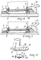
- the binding with quick boot locking particularly for snowboards, according to the present invention, comprises a base plate, generally designated by the reference numeral 1, which is provided with the typical circular opening 2 in which the fixing disk engages; said fixing disk is not shown in the accompanying drawings and allows to connect the base plate to the snowboard with the chosen angle.
- support which is generally designated by the reference numeral 3 and is arranged diametrically opposite, relative to the opening 2, to an abutment generally designated by the reference numeral 4.
- the abutment 4 is constituted by a secondary plate 5 which can be connected to the main plane 2 by means of screws 6 which engage elongated slots 7, so that it is possible to adjust the distance with respect to the diametrically opposite support.
- the secondary plate 5 is provided with frustum-shaped centering protrusions 8 which engage corresponding frustum-shaped seats 9 formed on a counterplate, generally designated by the reference numeral 10, which can be fixed below the sole 11 of a boot, generally designated by the reference numeral 12.
- the coupling between the protrusions 8 and the frustum-shaped seats 9 performs the important function of allowing very easy positioning of the counterplate, and therefore of the boot, on the binding for quick and easy coupling of the boot.
- the counterplate 10 is provided with fixing holes 13 which are arranged in a quadrilateral pattern in order to allow uniform stress distribution.
- protective flaps 15 which protrude from the plane formed by the counterplate in order to substantially engage the lateral edges of the boot, so as to act as a protective element and better delimit the region where the counterplate 10 engages the support 3 and the quick coupling means, generally designated by the reference numeral 20, which act diametrically with respect to the abutment 4.
- the quick coupling means are connected at the support 3, which forms a base 22 from which side walls 23 protrude; said side walls act as a support for an actuation lever, generally designated by the reference numeral 30, which is pivoted at 29 to the side walls so that it can oscillate.
- the actuation lever 30 is provided with lateral protrusions 31 which extend from the sides 32, which are connected by a cross-member 33 and have, at their free end, an insertion end 34 which enters the frustum-shaped seats 9 of the counterplate 10.
- the insertion of the ends 34 in the seats 9 generates a lateral compression which reduces the plays in the coupling of the seats 9 of the counterplate 10 with the protrusions 8 on one side and with the ends 34 on the other side, increasing the rigidity of the system.
- Pusher springs 35 act on the cross-member 33 and abut, at their other end, against the base of the support 3 in order to keep the lever in raised position with respect to the base plate in the inactive condition.
- the sides 32 form elongated slots 39 for engaging a pin 40 which is supported in a median portion of a locking pawl 41 which oscillates, at one of its ends, with respect to a pivot 43 which can rotate with respect to seats 44 of the side walls 23 and forms, at its other end, a pawl-shaped tooth 45 which can be inserted above the counterplate 10 in the region delimited by the flap 15 in order to push it into the locking position.
- the locking pawl 41 On the side opposite to the one provided with the pawl-shaped tooth 45, the locking pawl 41 has a tooth-shaped protrusion 50 which forms an abutment portion 50a directed upward and an inclined blending portion 50b directed toward the pivoting point.
- a locking lever engages the back of the locking pawl 41 and is pivoted to the side walls 23; said lever forms a locking tooth 61 which, when the quick coupling means are open, couples to the abutment portion 50a of the tooth 50.
- the locking lever 60 on the opposite side with respect to the locking tooth 61, has tabs 64 against which locking springs 65 act; said springs abut against the base 22 and keep the locking lever pressed against the pawl in order to make the locking tooth 61 engage the blending portion 50b when the locking pawl has fastened onto the counterplate, thus keeping it locked by pushing.
- a safety lever designated by the reference numeral 70, which is pivoted in a median portion 71 to the side walls of the locking lever and has a button-shaped portion 72 which protrudes into an opening 73 formed by the locking lever and has, at the other end, a toothed end 75 which engages an abutment for the safety lever 76 which is rigidly associated with the support 20 in order to prevent the accidental rotary actuation of the locking lever 60 if the safety lever 70 has not been actuated first by acting on its button-shaped portion 72 in contrast with the contrast spring 76.
- the assembly is completed by a covering fairing 80 which covers the entire part of the mechanisms.
- a complementary counterplate 90 which is arranged inside the boot and has rotation-preventing impressions 91 in which corresponding flanges 92 of bushes 93 enter; the screws 94 that enter the holes 13 of the counterplate 10 engage in said bushes.
- the quick coupling means act laterally in order to engage the counterplate that is fixed below the sole and are actuated by means of an oscillation along an axis which is substantially parallel to the longitudinal extension of the sole.
- the counterplate 10 is arranged below the secondary plate 5, while it rests above the protrusions 31 of the actuation lever.
- the actuation lever 30 By applying compression to the actuation lever, by means of the thrust applied by the counterplate to the protrusions, the actuation lever 30 is caused to rotate counterclockwise, with respect to the drawings, and draws, during its rotation, the locking pawl by means of the pin 40 that slides in the slots 39.
- the locking pawl is then rotated counterclockwise, with reference to the drawings, until its pawl-shaped portion engages below the flap 15, locking the counterplate.
- the rotation of the pawl-shaped lever causes the tooth 61 of the locking lever, which was previously engaged with the abutment portion 50a of the abutment 50, to engage the blending portion 50b, applying a further thrust.
- the rotation of the locking lever causes the rotation of the safety lever, which makes the toothed portion 75 engage the abutment 76 for the safety lever, so that locking against accidental openings is achieved.
- Another important aspect is also constituted by the fact that the release operations are equally simple, although providing safety against accidental openings, since it is necessary to act first on a safety lever which is accommodated inside the locking lever.
- the materials employed, as well as the contingent shapes and dimensions may be any according to requirements.
Landscapes
- Footwear And Its Accessory, Manufacturing Method And Apparatuses (AREA)
- Tires In General (AREA)
Applications Claiming Priority (2)
| Application Number | Priority Date | Filing Date | Title |
|---|---|---|---|
| IT96MI002195A IT1285538B1 (it) | 1996-10-22 | 1996-10-22 | Attacco con bloccaggio rapido della calzatura particolarmente per tavole da neve |
| ITMI962195 | 1996-10-22 |
Publications (2)
| Publication Number | Publication Date |
|---|---|
| EP0838247A2 true EP0838247A2 (fr) | 1998-04-29 |
| EP0838247A3 EP0838247A3 (fr) | 1999-03-03 |
Family
ID=11375074
Family Applications (1)
| Application Number | Title | Priority Date | Filing Date |
|---|---|---|---|
| EP97117949A Withdrawn EP0838247A3 (fr) | 1996-10-22 | 1997-10-16 | Fixation avec une bloquage de chaussure rapide, en particulier pour planche de glisse |
Country Status (4)
| Country | Link |
|---|---|
| US (1) | US6116636A (fr) |
| EP (1) | EP0838247A3 (fr) |
| JP (1) | JPH10127854A (fr) |
| IT (1) | IT1285538B1 (fr) |
Cited By (3)
| Publication number | Priority date | Publication date | Assignee | Title |
|---|---|---|---|---|
| EP0838250A1 (fr) * | 1996-10-25 | 1998-04-29 | Salomon S.A. | Dispositif de retenue d'une chaussure sur une planche de glisse |
| FR2803768A1 (fr) * | 2000-01-13 | 2001-07-20 | Rossignol Sa | Fixation automatique de surf a neige |
| EP1199952A4 (fr) * | 1999-06-02 | 2005-01-26 | Vans Inc | Interface pour chaussure de sport |
Families Citing this family (6)
| Publication number | Priority date | Publication date | Assignee | Title |
|---|---|---|---|---|
| US6648365B1 (en) * | 1997-01-08 | 2003-11-18 | The Burton Corporation | Snowboard binding |
| AUPO954697A0 (en) * | 1997-09-30 | 1997-10-23 | Powder Design Pty. Ltd. | Snowboard safety release binding |
| US6168173B1 (en) * | 1997-11-19 | 2001-01-02 | The Burton Corporation | Snowboard boot with binding interface |
| US6708065B2 (en) * | 2001-03-02 | 2004-03-16 | Cardiac Pacemakers, Inc. | Antenna for an implantable medical device |
| US7613522B2 (en) | 2006-06-09 | 2009-11-03 | Cardiac Pacemakers, Inc. | Multi-antenna for an implantable medical device |
| US7720544B2 (en) * | 2006-06-09 | 2010-05-18 | Cardiac Pacemakers, Inc. | Systems for enabling telemetry in an implantable medical device |
Citations (3)
| Publication number | Priority date | Publication date | Assignee | Title |
|---|---|---|---|---|
| US5236216A (en) * | 1991-07-10 | 1993-08-17 | F2 International Ges.M.B.H. | Binding for snowboards |
| WO1996022137A2 (fr) * | 1995-01-20 | 1996-07-25 | The Burton Corporation | Fixation d'une chaussure sur une planche a neige |
| WO1996026774A2 (fr) * | 1995-03-02 | 1996-09-06 | Items International, Inc. | Ensemble fixation pour planche de surf des neiges |
Family Cites Families (12)
| Publication number | Priority date | Publication date | Assignee | Title |
|---|---|---|---|---|
| DE3107036A1 (de) * | 1981-02-25 | 1982-09-09 | Hannes Marker Sicherheits-Skibindungen GmbH & Co KG, 8100 Garmisch-Partenkirchen | Fersenhalter einer sicherheits-skibindung |
| US5890730A (en) * | 1994-08-18 | 1999-04-06 | Switch Manufacturing | Snowboard boot and binding apparatus |
| US4973073A (en) * | 1989-03-17 | 1990-11-27 | Raines Mark A | Snowboard binding |
| US5299823A (en) * | 1993-01-28 | 1994-04-05 | John Glaser | Snow board binding and method |
| US5971420A (en) * | 1994-06-06 | 1999-10-26 | Shimano, Inc. | Snowboard binding |
| US5520406A (en) * | 1994-08-18 | 1996-05-28 | Switch Manufacturing | Snowboard binding |
| US5673927A (en) * | 1994-08-25 | 1997-10-07 | Vermillion; James H. | Composite snowboard insert and method of installation |
| US5722680A (en) * | 1996-05-29 | 1998-03-03 | The Burton Corporation | Step-in snowboard binding |
| US5690351A (en) * | 1995-07-21 | 1997-11-25 | Karol; Chris | Snowboard binding system |
| DE19544696A1 (de) * | 1995-11-30 | 1997-06-05 | Marker Deutschland Gmbh | Bindung für Snowboards o. dgl. |
| US5713594A (en) * | 1996-07-18 | 1998-02-03 | Jenni; David Christian | Snow board binding |
| FR2755027B1 (fr) * | 1996-10-25 | 1999-01-15 | Salomon Sa | Dispositif de retenue d'une chaussure sur une planche de glisse destinee a la pratique du surf sur la neige |
-
1996
- 1996-10-22 IT IT96MI002195A patent/IT1285538B1/it active IP Right Grant
-
1997
- 1997-10-16 US US08/951,372 patent/US6116636A/en not_active Expired - Fee Related
- 1997-10-16 EP EP97117949A patent/EP0838247A3/fr not_active Withdrawn
- 1997-10-21 JP JP9288085A patent/JPH10127854A/ja active Pending
Patent Citations (3)
| Publication number | Priority date | Publication date | Assignee | Title |
|---|---|---|---|---|
| US5236216A (en) * | 1991-07-10 | 1993-08-17 | F2 International Ges.M.B.H. | Binding for snowboards |
| WO1996022137A2 (fr) * | 1995-01-20 | 1996-07-25 | The Burton Corporation | Fixation d'une chaussure sur une planche a neige |
| WO1996026774A2 (fr) * | 1995-03-02 | 1996-09-06 | Items International, Inc. | Ensemble fixation pour planche de surf des neiges |
Cited By (3)
| Publication number | Priority date | Publication date | Assignee | Title |
|---|---|---|---|---|
| EP0838250A1 (fr) * | 1996-10-25 | 1998-04-29 | Salomon S.A. | Dispositif de retenue d'une chaussure sur une planche de glisse |
| EP1199952A4 (fr) * | 1999-06-02 | 2005-01-26 | Vans Inc | Interface pour chaussure de sport |
| FR2803768A1 (fr) * | 2000-01-13 | 2001-07-20 | Rossignol Sa | Fixation automatique de surf a neige |
Also Published As
| Publication number | Publication date |
|---|---|
| IT1285538B1 (it) | 1998-06-08 |
| EP0838247A3 (fr) | 1999-03-03 |
| US6116636A (en) | 2000-09-12 |
| ITMI962195A1 (it) | 1998-04-22 |
| JPH10127854A (ja) | 1998-05-19 |
Similar Documents
| Publication | Publication Date | Title |
|---|---|---|
| CA2115825C (fr) | Systeme de fixation pour planches de glisse, particulierement les planches a neige; et bottes a utiliser avec ce systeme | |
| JP3050220U (ja) | スノーボード用踏込み式ビンディング | |
| US4683620A (en) | Safety closure device particularly for ski boots | |
| US4112557A (en) | Devices for fastening ski boots | |
| US5915721A (en) | Step-in boot binding | |
| CN1750859B (zh) | 用于保持连接到滑雪板上的靴的靴固定装置 | |
| JP3084295U (ja) | スノーボードバインディングおよびスノーボードバインディング機構 | |
| KR101532088B1 (ko) | 스포츠 보드용의 도구 없이 조정가능한 바인딩 장치 | |
| US6116636A (en) | Binding with quick boot locking action particularly for snowboards | |
| EP0824942A1 (fr) | Fixation pour surf de neige | |
| CA2211241A1 (fr) | Dispositif pour fixer une sangle dentee, en particulier pour une attache de fermeture pour chaussures de sport | |
| US20060027981A1 (en) | Binding for a sports boot on a gliding board | |
| JP2010507420A (ja) | 調整可能な甲要素を備えるスノーボード用ビンディング | |
| US5005303A (en) | Alpine ski boot | |
| JPH09206420A (ja) | スノーボード用のビンディング | |
| JP3088015U (ja) | スノーボードビンディングがロックされたことを示す方法および装置 | |
| US6101745A (en) | Locking devices for sports footwear, in particular for ski-boots | |
| JPH05184403A (ja) | 胴部の枢動を不動固定する装置を備えたスキー靴 | |
| JP4159613B2 (ja) | スノーボードなどの締め具 | |
| EP1310276B1 (fr) | Dispositif pour l'interconnection d'une fixation de ski sur un ski | |
| US5592722A (en) | Closure device, particularly for sports shoes | |
| CN117205529A (zh) | 用于滑行板上的鞋的保持装置和包含这种装置的滑行器械 | |
| US6742801B1 (en) | Snowboard boot binding mechanism | |
| CN112492878B (zh) | 具有在壳体基部由支撑壳体相对基座的转动轴形成的鞋靴止挡器的滑雪板固定装置 | |
| US8060990B2 (en) | Binding buckle with secure docking element |
Legal Events
| Date | Code | Title | Description |
|---|---|---|---|
| PUAI | Public reference made under article 153(3) epc to a published international application that has entered the european phase |
Free format text: ORIGINAL CODE: 0009012 |
|
| AK | Designated contracting states |
Kind code of ref document: A2 Designated state(s): AT CH DE FR IT LI |
|
| AX | Request for extension of the european patent |
Free format text: AL;LT;LV;RO;SI |
|
| PUAL | Search report despatched |
Free format text: ORIGINAL CODE: 0009013 |
|
| AK | Designated contracting states |
Kind code of ref document: A3 Designated state(s): AT BE CH DE DK ES FI FR GB GR IE IT LI LU MC NL PT SE |
|
| AX | Request for extension of the european patent |
Free format text: AL;LT;LV;RO;SI |
|
| AKX | Designation fees paid | ||
| 17P | Request for examination filed |
Effective date: 19991029 |
|
| RBV | Designated contracting states (corrected) |
Designated state(s): AT BE CH DE DK LI |
|
| RBV | Designated contracting states (corrected) |
Designated state(s): AT CH DE FR IT LI |
|
| 17Q | First examination report despatched |
Effective date: 20021115 |
|
| STAA | Information on the status of an ep patent application or granted ep patent |
Free format text: STATUS: THE APPLICATION IS DEEMED TO BE WITHDRAWN |
|
| 18D | Application deemed to be withdrawn |
Effective date: 20030527 |