EP0838323B1 - Procédé de moulage par soufflage - Google Patents
Procédé de moulage par soufflage Download PDFInfo
- Publication number
- EP0838323B1 EP0838323B1 EP97650045A EP97650045A EP0838323B1 EP 0838323 B1 EP0838323 B1 EP 0838323B1 EP 97650045 A EP97650045 A EP 97650045A EP 97650045 A EP97650045 A EP 97650045A EP 0838323 B1 EP0838323 B1 EP 0838323B1
- Authority
- EP
- European Patent Office
- Prior art keywords
- parison
- blow pin
- blow
- mould halves
- mould
- Prior art date
- Legal status (The legal status is an assumption and is not a legal conclusion. Google has not performed a legal analysis and makes no representation as to the accuracy of the status listed.)
- Expired - Lifetime
Links
Images


Classifications
-
- B—PERFORMING OPERATIONS; TRANSPORTING
- B29—WORKING OF PLASTICS; WORKING OF SUBSTANCES IN A PLASTIC STATE IN GENERAL
- B29C—SHAPING OR JOINING OF PLASTICS; SHAPING OF MATERIAL IN A PLASTIC STATE, NOT OTHERWISE PROVIDED FOR; AFTER-TREATMENT OF THE SHAPED PRODUCTS, e.g. REPAIRING
- B29C49/00—Blow-moulding, i.e. blowing a preform or parison to a desired shape within a mould; Apparatus therefor
- B29C49/42—Component parts, details or accessories; Auxiliary operations
- B29C49/58—Blowing means
- B29C49/60—Blow-needles
-
- B—PERFORMING OPERATIONS; TRANSPORTING
- B29—WORKING OF PLASTICS; WORKING OF SUBSTANCES IN A PLASTIC STATE IN GENERAL
- B29C—SHAPING OR JOINING OF PLASTICS; SHAPING OF MATERIAL IN A PLASTIC STATE, NOT OTHERWISE PROVIDED FOR; AFTER-TREATMENT OF THE SHAPED PRODUCTS, e.g. REPAIRING
- B29C49/00—Blow-moulding, i.e. blowing a preform or parison to a desired shape within a mould; Apparatus therefor
- B29C49/02—Combined blow-moulding and manufacture of the preform or the parison
- B29C49/04—Extrusion blow-moulding
-
- B—PERFORMING OPERATIONS; TRANSPORTING
- B29—WORKING OF PLASTICS; WORKING OF SUBSTANCES IN A PLASTIC STATE IN GENERAL
- B29C—SHAPING OR JOINING OF PLASTICS; SHAPING OF MATERIAL IN A PLASTIC STATE, NOT OTHERWISE PROVIDED FOR; AFTER-TREATMENT OF THE SHAPED PRODUCTS, e.g. REPAIRING
- B29C49/00—Blow-moulding, i.e. blowing a preform or parison to a desired shape within a mould; Apparatus therefor
- B29C49/42—Component parts, details or accessories; Auxiliary operations
- B29C49/78—Measuring, controlling or regulating
- B29C49/783—Measuring, controlling or regulating blowing pressure
- B29C2049/7832—Blowing with two or more pressure levels
Definitions
- the invention relates to a method of blow-moulding thermoplastics material to form a blow moulded article such as a case, for example, a tool case comprising two case halves having an integrally moulded hinge therebetween.
- blow-moulded articles by firstly extruding a tube or parison of hot thermoplastics material, bringing two halves of a mould together on opposite sides of the parison and inserting a blow pin through the mould into the parison. Air is then blown into the interior of the parison through the blow pin at high pressure to inflate the thermoplastics material against the walls of the mould. After a preset time when the moulding has set, the two halves of the mould are separated and the moulded article is released.
- the blow pin which penetrates the wall of the mould comprises a sharpened tip which is normally chamfered.
- the sharpened tip essentially rips through the wall of the parison resulting in a ragged edge through which air may back-leak out from the mould.
- a relatively low moulding pressure of between 3 and 5 bar is generally only achievable using conventional technology. This results in an unsatisfactory surface finish as the air pressure is insufficient to avoid flow wrinkles being visible on the surface of the moulding where distribution of thermoplastics material has been uneven.
- the small apertures left in the moulding after withdrawal of the blow pins are frequently poorly formed which again detracts from the surface finish of the finished product.
- This invention is therefore directed towards providing an improved method of blow moulding which will overcome at least some of these difficulties.
- thermoplastics material in a blow moulding apparatus comprising:
- the mould halves are closed in timed relation to the blowing of the low pressure air.
- the wall of the parison is deformed by blowing low pressure air at a pressure of from 3 to 5 bar against the parison.
- the high pressure air at a pressure of from 8 to 10 bar is blown through the blow pin to inflate the parison.
- the low pressure air is blown through a parison-deforming outlet hole at the end of a blowing pin to provide a stream of low pressure air directed against the parison to deform the parison at the point of entry of the blowing pin into the parison.
- the high pressure air is blown through blow pin inflation outlet means in a side wall of the blow pin to inflate the parison against the walls of the mould.
- the blow pin inflation means comprises at least two outlets in the side wall of the blow pin.
- blow pin inflation outlets There may be two blow pin inflation outlets which are substantially diametrically opposed in the side wall of the blow pin.
- the blow pin inflation means comprises four outlets spaced-apart around the side wall of the blow pin.
- the parison deforming outlet also provides a blow pin inflation outlet.
- the mould halves are closed to a distance of less than 100mm apart before low pressure air is blown against the parison.
- the mould halves are closed to a distance of less than 25mm apart before low pressure air is blown against the parison.
- the method includes the step of initiating a timer to control the blowing of the low pressure air on partial closing of the mould halves.
- the invention also provides a blow moulded article, especially a blow moulded case whenever produced by the method of the invention.
- thermoplastics material there is illustrated a method of blow-moulding thermoplastics material according to the invention.
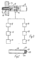
- a blend of thermoplastics material is delivered into a mould 1 comprising two mould halves 2, 3.
- a parison 4 of hot thermoplastic material is extruded as the mould halves 2, 3 are closed towards one another.
- a stress force is applied to the wall of the parison 4 in this case by a projection 5 extending from one of the mould halves 3 over which the parison 4 is passed.
- the stress force is applied in the main body of the article being moulded.
- the projection 5 defines a sleeve for a blow pin 10 which is movable by a piston 11 from a retracted position as illustrated in Figs.
- the parison 4 flows over the mould half 3, it is pretensioned by the projection or sleeve 5 as illustrated in Fig. 2(b).
- the pre-close distance between the mould halves 2, 3 is at most 100mm, and is typically 25mm.
- the article may be a blow moulded case for speciality tools and the like.
- the blow pin 10 is operated under the control of a control system illustrated in Fig. 3 and comprising a proximity switch 11 to monitor when the mould halves 2, 3 are in the pre-close position illustrated in Fig. 3, a delay timer 12 and a low pressure solenoid valve 13.
- a similar control system is provided for high pressure air.
- the blow pin 10 is mounted in a mounting block 15 having an inlet port 16 for high pressure air at a pressure of typically 8 to 10 bar and for low pressure air at a pressure of typically 3 to 5 bar.
- the blow pin 10 has a rounded tip 21 to prevent damage to a parison 4 on insertion.
- the tip 21 in this case has a single parison deforming outlet hole 22.
- Blow pin inflation outlet means is in this case provided by two substantially diametrically opposed blow pin inflation outlet holes 23 in the side wall of the blow pin 10 stepped back from the tip 21 of the pin 10.
- a stress force may be applied to the wall of the parison either by providing a projection from a mould over which the parison wall passes and/or by blowing air at a low pressure against the parison through a blow pin.
- the invention offers very considerable advantages. Because of the lower pressure used, the delayed mould closing, the controlled timing and the modified blow pin it is possible to form blow holes more reliably than by using standard techniques. Lighter walled parisons may be used resulting in materials savings. Different materials which have lower melt strengths may also be used. In addition, production efficiency is optimised as there is no risk of blockages in the blow pin.
- thermoplastics with the mould surface with consequent improved heat transfer and cooling efficiencies which in turn leads to lower cycle times and improved rates of production.
Landscapes
- Engineering & Computer Science (AREA)
- Manufacturing & Machinery (AREA)
- Mechanical Engineering (AREA)
- Blow-Moulding Or Thermoforming Of Plastics Or The Like (AREA)
Claims (12)
- Procédé d'extrusion-soufflage de matières thermoplastiques dans un dispositif d'extrusion-soufflage comprenant :le procédé comprenant les étapes de :une paire de moitiés de moule (2, 3) ;une tige de soufflage (10) ayant une pointe arrondie pénétrante, la pointe pénétrante ayant une sortie d'air (22) ; etun manchon (5) ayant la forme d'une saillie (6) depuis l'une des moitiés de moule (2, 3) ;la tige de soufflage (10) étant montée dans le manchon (5) en vue de se déplacerentre une position rétractée et une position pénétrante déployée ;extrusion d'une ébauche (4) de matière thermoplastique chaude ;fermeture partielle de la paire de moitiés de moule (2, 3) autour de l'ébauche extrudée (4) ;application d'une force de contrainte localisée sur une aire de réception de tige de soufflage de la paroi d'une ébauche (4) comme les moitiés de moule (2, 3) se ferment ;la force de contrainte localisée étant appliquée en engageant le manchon (5) contre l'ébauche (4) et en appliquant de l'air à travers le trou de sortie (22) dansla pointe pénétrante de la tige de soufflage (10) dans la position rétractée dans le manchon (5) à une basse pression comme les moitiés de moule (2, 3) continuent de se fermer ;lors de la fermeture des moitiés de moule (2, 3), déplacement de la tige de soufflage (10) dans la position déployée et pénétration de l'aire pré-contrainte de l'ébauche (4) avec la pointe arrondie de la tige de soufflage (10) ;soufflage d'air à une haute pression à travers la tige de soufflage (10) quand les moitiés de moule (2, 3) sont fermées et l'ébauche (4) est pénétrée par la tige de soufflage (10) en vue de former un joint étanche à l'air entre l'ébauche (4) et la tige de soufflage (10) et de gonfler l'ébauche (4) contre les parois des moitiés de moule (2, 3) ;retrait de la tige de soufflage (10) de l'ébauche (4) ; etlibération d'un article extrudé par soufflage du moule après un temps préétabli.
- Procédé selon l'une quelconque des revendications 2 à 4 [sic], dans lequel les moitiés de moule (2, 3) sont fermées selon une relation minutée avec le soufflage de l'air à basse pression.
- Procédé selon la revendication 1 ou 2, dans lequel la paroi de l'ébauche (4) est déformée par soufflage d'air à basse pression à une pression de 3 à 5 bars contre l'ébauche (4).
- Procédé selon l'une quelconque des revendications précédentes, dans lequel de l'air à haute pression à une pression de 8 à 10 bars est soufflé à travers la tige de soufflage (10) pour gonfler l'ébauche.
- Procédé selon l'une quelconque des revendications précédentes, dans lequel après l'insertion de la tige de soufflage (10) dans l'ébauche (4), de l'air à haute pression est soufflé à travers un moyen de sortie de gonflage de tige de soufflage (23) dans une paroi latérale de la tige de soufflage (10) afin de gonfler l'ébauche (4) contre les parois du moule.
- Procédé selon la revendication 5, dans lequel le moyen de sortie de gonflage de tige de soufflage (23) comprend au moins deux sorties (23) dans la paroi latérale de la tige de soufflage (10).
- Procédé selon la revendication 6, dans lequel existent deux sorties de gonflage de tige de soufflage (23) qui sont substantiellement diamétralement opposées dans la paroi latérale de la tige de soufflage (1).
- Procédé selon la revendication 5 ou 6, dans lequel le moyen de gonflage de tige de soufflage (23) comprend quatre sorties (23) espacées autour de la paroi latérale de la tige de soufflage (10).
- Procédé selon l'une quelconque des revendications 5 à 8, dans lequel la sortie de déformation d'ébauche (22) fournit aussi une sortie de gonflage de tige de soufflage.
- Procédé selon l'une quelconque des revendications précédentes, dans lequel les moitiés de moule (2, 3) sont fermées à une distance de moins de 100 mm l'une de l'autre avant que l'air à basse pression ne soit soufflé contre l'ébauche (4).
- Procédé selon l'une quelconque des revendications précédentes, dans lequel les moitiés de moule (2, 3) sont fermées à une distance de moins de 25 mm l'une de l'autre avant que l'air à basse pression ne soit soufflé contre l'ébauche (4).
- Procédé selon l'une quelconque des revendications précédentes, comportant l'étape de lancement d'une minuterie pour commander le soufflage de l'air à basse pression lors de la fermeture partielle des moitiés de moule (2, 3).
Applications Claiming Priority (4)
| Application Number | Priority Date | Filing Date | Title |
|---|---|---|---|
| IE960750 | 1996-10-25 | ||
| IE960750 | 1996-10-25 | ||
| IE960900 | 1996-12-18 | ||
| IE960900A IE960900A1 (en) | 1996-10-25 | 1996-12-18 | A method of blow-moulding |
Publications (2)
| Publication Number | Publication Date |
|---|---|
| EP0838323A1 EP0838323A1 (fr) | 1998-04-29 |
| EP0838323B1 true EP0838323B1 (fr) | 2002-09-11 |
Family
ID=26319981
Family Applications (1)
| Application Number | Title | Priority Date | Filing Date |
|---|---|---|---|
| EP97650045A Expired - Lifetime EP0838323B1 (fr) | 1996-10-25 | 1997-10-24 | Procédé de moulage par soufflage |
Country Status (4)
| Country | Link |
|---|---|
| EP (1) | EP0838323B1 (fr) |
| AT (1) | ATE223801T1 (fr) |
| DE (1) | DE69715342T2 (fr) |
| IE (1) | IE960900A1 (fr) |
Citations (1)
| Publication number | Priority date | Publication date | Assignee | Title |
|---|---|---|---|---|
| US4025276A (en) * | 1976-02-13 | 1977-05-24 | Phillips Petroleum Company | Blow molding apparatus |
Family Cites Families (5)
| Publication number | Priority date | Publication date | Assignee | Title |
|---|---|---|---|---|
| FR1475911A (fr) * | 1966-02-24 | 1967-04-07 | Unilever Nv | Procédé et dispositif pour la fabrication d'un corps creux en matière thermoplatique et article en résultant |
| US3571848A (en) * | 1969-01-14 | 1971-03-23 | Continental Can Co | High exhaust needle |
| US3973896A (en) * | 1975-06-12 | 1976-08-10 | Phillips Petroleum Company | Blow molding apparatus |
| US4799876A (en) * | 1988-02-22 | 1989-01-24 | Phillips Petroleum Company | Blow molding apparatus |
| IES930126A2 (en) * | 1993-02-22 | 1993-08-25 | Plastech Developments Ltd | A blow-moulding process |
-
1996
- 1996-12-18 IE IE960900A patent/IE960900A1/en not_active IP Right Cessation
-
1997
- 1997-10-24 EP EP97650045A patent/EP0838323B1/fr not_active Expired - Lifetime
- 1997-10-24 AT AT97650045T patent/ATE223801T1/de not_active IP Right Cessation
- 1997-10-24 DE DE69715342T patent/DE69715342T2/de not_active Expired - Lifetime
Patent Citations (1)
| Publication number | Priority date | Publication date | Assignee | Title |
|---|---|---|---|---|
| US4025276A (en) * | 1976-02-13 | 1977-05-24 | Phillips Petroleum Company | Blow molding apparatus |
Also Published As
| Publication number | Publication date |
|---|---|
| IE960900A1 (en) | 1998-05-06 |
| DE69715342T2 (de) | 2003-05-15 |
| DE69715342D1 (de) | 2002-10-17 |
| ATE223801T1 (de) | 2002-09-15 |
| EP0838323A1 (fr) | 1998-04-29 |
Similar Documents
| Publication | Publication Date | Title |
|---|---|---|
| US5863489A (en) | Method of blow-moulding | |
| US4065535A (en) | Thread forming and neck finishing process | |
| US5795533A (en) | Method and device for the manufacturing of hollow articles made from thermoplastic material by blow moulding | |
| US4865799A (en) | Method for aligning extruded parison into sepentine-shaped mold cavity | |
| JP4146234B2 (ja) | 中心からずれた口を有するポリエチレンテレフタレート容器の製造方法 | |
| US2913762A (en) | Plastic molding machine | |
| EP0278400B1 (fr) | Dispositif pour la fabrication d'un corps creux en matière plastique avec un corps moulé par soufflage | |
| US6220842B1 (en) | Production apparatus of expansion-molded article and auxiliary member for transfer of foamed particles | |
| US3973896A (en) | Blow molding apparatus | |
| US3052916A (en) | Method of and apparatus for making plastic articles | |
| US2908034A (en) | Method and apparatus for making blown plastic articles | |
| US20020041913A1 (en) | Mold for suction/blowing system | |
| CA1074970A (fr) | Procede de moulage par soufflage | |
| US3538211A (en) | Bottle blowing process and apparatus | |
| EP0838323B1 (fr) | Procédé de moulage par soufflage | |
| US7037101B2 (en) | Center cylinder ejection assist | |
| EP0241040A1 (fr) | Fabrication de bouteilles en plastique | |
| US3933417A (en) | Apparatus for forming multiaxially oriented containers | |
| EP0627296B1 (fr) | Procede de moulage par soufflage d'un recipient creux, et cylindre a air de soufflage | |
| US5465908A (en) | Gas-feeding nozzle | |
| JP2000000880A (ja) | ブロ―成形装置およびその成形方法 | |
| IES58331B2 (en) | A blow-moulding process | |
| US5449284A (en) | Compression molding and trimming blow pin assembly | |
| JPS63134220A (ja) | ブロ−成形機の制御方法及びその装置 | |
| JP2685292B2 (ja) | プラスチック製中空容器の製造方法および製造装置 |
Legal Events
| Date | Code | Title | Description |
|---|---|---|---|
| PUAI | Public reference made under article 153(3) epc to a published international application that has entered the european phase |
Free format text: ORIGINAL CODE: 0009012 |
|
| AK | Designated contracting states |
Kind code of ref document: A1 Designated state(s): AT BE CH DE DK ES FI FR GR IT LI LU MC NL PT SE |
|
| AX | Request for extension of the european patent |
Free format text: AL;LT;LV;RO;SI |
|
| 17P | Request for examination filed |
Effective date: 19980602 |
|
| AKX | Designation fees paid |
Free format text: AT BE CH DE DK ES FI FR GB GR IE IT LI LU MC NL PT SE |
|
| RBV | Designated contracting states (corrected) |
Designated state(s): AT BE CH DE DK ES FI FR GB GR IE IT LI LU MC NL PT SE |
|
| 17Q | First examination report despatched |
Effective date: 20010814 |
|
| RBV | Designated contracting states (corrected) |
Designated state(s): AT BE CH DE DK ES FI FR GR IT LI LU MC NL PT SE |
|
| GRAG | Despatch of communication of intention to grant |
Free format text: ORIGINAL CODE: EPIDOS AGRA |
|
| GRAG | Despatch of communication of intention to grant |
Free format text: ORIGINAL CODE: EPIDOS AGRA |
|
| GRAH | Despatch of communication of intention to grant a patent |
Free format text: ORIGINAL CODE: EPIDOS IGRA |
|
| GRAH | Despatch of communication of intention to grant a patent |
Free format text: ORIGINAL CODE: EPIDOS IGRA |
|
| GRAA | (expected) grant |
Free format text: ORIGINAL CODE: 0009210 |
|
| AK | Designated contracting states |
Kind code of ref document: B1 Designated state(s): AT BE CH DE DK ES FI FR GR IT LI LU MC NL PT SE |
|
| PG25 | Lapsed in a contracting state [announced via postgrant information from national office to epo] |
Ref country code: NL Free format text: LAPSE BECAUSE OF FAILURE TO SUBMIT A TRANSLATION OF THE DESCRIPTION OR TO PAY THE FEE WITHIN THE PRESCRIBED TIME-LIMIT Effective date: 20020911 Ref country code: LI Free format text: LAPSE BECAUSE OF FAILURE TO SUBMIT A TRANSLATION OF THE DESCRIPTION OR TO PAY THE FEE WITHIN THE PRESCRIBED TIME-LIMIT Effective date: 20020911 Ref country code: IT Free format text: LAPSE BECAUSE OF FAILURE TO SUBMIT A TRANSLATION OF THE DESCRIPTION OR TO PAY THE FEE WITHIN THE PRESCRIBED TIME-LIMIT;WARNING: LAPSES OF ITALIAN PATENTS WITH EFFECTIVE DATE BEFORE 2007 MAY HAVE OCCURRED AT ANY TIME BEFORE 2007. THE CORRECT EFFECTIVE DATE MAY BE DIFFERENT FROM THE ONE RECORDED. Effective date: 20020911 Ref country code: GR Free format text: LAPSE BECAUSE OF FAILURE TO SUBMIT A TRANSLATION OF THE DESCRIPTION OR TO PAY THE FEE WITHIN THE PRESCRIBED TIME-LIMIT Effective date: 20020911 Ref country code: FR Free format text: LAPSE BECAUSE OF FAILURE TO SUBMIT A TRANSLATION OF THE DESCRIPTION OR TO PAY THE FEE WITHIN THE PRESCRIBED TIME-LIMIT Effective date: 20020911 Ref country code: FI Free format text: LAPSE BECAUSE OF FAILURE TO SUBMIT A TRANSLATION OF THE DESCRIPTION OR TO PAY THE FEE WITHIN THE PRESCRIBED TIME-LIMIT Effective date: 20020911 Ref country code: CH Free format text: LAPSE BECAUSE OF FAILURE TO SUBMIT A TRANSLATION OF THE DESCRIPTION OR TO PAY THE FEE WITHIN THE PRESCRIBED TIME-LIMIT Effective date: 20020911 Ref country code: BE Free format text: LAPSE BECAUSE OF FAILURE TO SUBMIT A TRANSLATION OF THE DESCRIPTION OR TO PAY THE FEE WITHIN THE PRESCRIBED TIME-LIMIT Effective date: 20020911 Ref country code: AT Free format text: LAPSE BECAUSE OF FAILURE TO SUBMIT A TRANSLATION OF THE DESCRIPTION OR TO PAY THE FEE WITHIN THE PRESCRIBED TIME-LIMIT Effective date: 20020911 |
|
| REF | Corresponds to: |
Ref document number: 223801 Country of ref document: AT Date of ref document: 20020915 Kind code of ref document: T |
|
| REG | Reference to a national code |
Ref country code: CH Ref legal event code: EP |
|
| REF | Corresponds to: |
Ref document number: 69715342 Country of ref document: DE Date of ref document: 20021017 |
|
| PG25 | Lapsed in a contracting state [announced via postgrant information from national office to epo] |
Ref country code: LU Free format text: LAPSE BECAUSE OF NON-PAYMENT OF DUE FEES Effective date: 20021024 |
|
| PG25 | Lapsed in a contracting state [announced via postgrant information from national office to epo] |
Ref country code: SE Free format text: LAPSE BECAUSE OF FAILURE TO SUBMIT A TRANSLATION OF THE DESCRIPTION OR TO PAY THE FEE WITHIN THE PRESCRIBED TIME-LIMIT Effective date: 20021211 Ref country code: DK Free format text: LAPSE BECAUSE OF FAILURE TO SUBMIT A TRANSLATION OF THE DESCRIPTION OR TO PAY THE FEE WITHIN THE PRESCRIBED TIME-LIMIT Effective date: 20021211 |
|
| PG25 | Lapsed in a contracting state [announced via postgrant information from national office to epo] |
Ref country code: PT Free format text: LAPSE BECAUSE OF FAILURE TO SUBMIT A TRANSLATION OF THE DESCRIPTION OR TO PAY THE FEE WITHIN THE PRESCRIBED TIME-LIMIT Effective date: 20021217 |
|
| NLV1 | Nl: lapsed or annulled due to failure to fulfill the requirements of art. 29p and 29m of the patents act | ||
| REG | Reference to a national code |
Ref country code: CH Ref legal event code: PL |
|
| PG25 | Lapsed in a contracting state [announced via postgrant information from national office to epo] |
Ref country code: ES Free format text: LAPSE BECAUSE OF FAILURE TO SUBMIT A TRANSLATION OF THE DESCRIPTION OR TO PAY THE FEE WITHIN THE PRESCRIBED TIME-LIMIT Effective date: 20030328 |
|
| PG25 | Lapsed in a contracting state [announced via postgrant information from national office to epo] |
Ref country code: MC Free format text: LAPSE BECAUSE OF NON-PAYMENT OF DUE FEES Effective date: 20030501 |
|
| EN | Fr: translation not filed | ||
| PLBE | No opposition filed within time limit |
Free format text: ORIGINAL CODE: 0009261 |
|
| STAA | Information on the status of an ep patent application or granted ep patent |
Free format text: STATUS: NO OPPOSITION FILED WITHIN TIME LIMIT |
|
| 26N | No opposition filed |
Effective date: 20030612 |
|
| REG | Reference to a national code |
Ref country code: DE Ref legal event code: R082 Ref document number: 69715342 Country of ref document: DE Representative=s name: MITSCHERLICH, PATENT- UND RECHTSANWAELTE PARTM, DE Effective date: 20130215 Ref country code: DE Ref legal event code: R082 Ref document number: 69715342 Country of ref document: DE Representative=s name: MITSCHERLICH, PATENT- UND RECHTSANWAELTE, PART, DE Effective date: 20130215 Ref country code: DE Ref legal event code: R082 Ref document number: 69715342 Country of ref document: DE Representative=s name: MITSCHERLICH & PARTNER PATENT- UND RECHTSANWAE, DE Effective date: 20130215 Ref country code: DE Ref legal event code: R081 Ref document number: 69715342 Country of ref document: DE Owner name: MERGON INTERNATIONAL, BM Free format text: FORMER OWNER: MENZA LTD., CASTLEPOLLARD, WESTMEATH, IE Effective date: 20130215 Ref country code: DE Ref legal event code: R081 Ref document number: 69715342 Country of ref document: DE Owner name: MERGON INTERNATIONAL, BM Free format text: FORMER OWNER: MENZA LTD., CASTLEPOLLARD, IE Effective date: 20130215 |
|
| PGFP | Annual fee paid to national office [announced via postgrant information from national office to epo] |
Ref country code: DE Payment date: 20160822 Year of fee payment: 20 |
|
| REG | Reference to a national code |
Ref country code: DE Ref legal event code: R071 Ref document number: 69715342 Country of ref document: DE |