EP0838353B1 - Bandage pneumatique pour véhicule - Google Patents
Bandage pneumatique pour véhicule Download PDFInfo
- Publication number
- EP0838353B1 EP0838353B1 EP97118415A EP97118415A EP0838353B1 EP 0838353 B1 EP0838353 B1 EP 0838353B1 EP 97118415 A EP97118415 A EP 97118415A EP 97118415 A EP97118415 A EP 97118415A EP 0838353 B1 EP0838353 B1 EP 0838353B1
- Authority
- EP
- European Patent Office
- Prior art keywords
- region
- tread
- tread strip
- rubber
- pneumatic vehicle
- Prior art date
- Legal status (The legal status is an assumption and is not a legal conclusion. Google has not performed a legal analysis and makes no representation as to the accuracy of the status listed.)
- Expired - Lifetime
Links
- 239000000203 mixture Substances 0.000 claims abstract description 40
- 229920001971 elastomer Polymers 0.000 claims abstract description 39
- 239000005060 rubber Substances 0.000 claims abstract description 39
- 239000011324 bead Substances 0.000 claims abstract description 5
- 238000010073 coating (rubber) Methods 0.000 claims description 7
- VYPSYNLAJGMNEJ-UHFFFAOYSA-N Silicium dioxide Chemical compound O=[Si]=O VYPSYNLAJGMNEJ-UHFFFAOYSA-N 0.000 claims description 6
- 239000000377 silicon dioxide Substances 0.000 claims description 3
- 239000006229 carbon black Substances 0.000 claims 1
- 239000000945 filler Substances 0.000 claims 1
- 230000000007 visual effect Effects 0.000 claims 1
- 238000005470 impregnation Methods 0.000 abstract 1
- 150000001875 compounds Chemical class 0.000 description 11
- 238000004519 manufacturing process Methods 0.000 description 9
- 238000001125 extrusion Methods 0.000 description 8
- 238000005096 rolling process Methods 0.000 description 5
- 238000009795 derivation Methods 0.000 description 4
- 238000000034 method Methods 0.000 description 4
- 239000004071 soot Substances 0.000 description 4
- 238000010276 construction Methods 0.000 description 3
- 239000000463 material Substances 0.000 description 3
- 238000005299 abrasion Methods 0.000 description 2
- 229920000642 polymer Polymers 0.000 description 2
- 238000000926 separation method Methods 0.000 description 2
- QFLWZFQWSBQYPS-AWRAUJHKSA-N (3S)-3-[[(2S)-2-[[(2S)-2-[5-[(3aS,6aR)-2-oxo-1,3,3a,4,6,6a-hexahydrothieno[3,4-d]imidazol-4-yl]pentanoylamino]-3-methylbutanoyl]amino]-3-(4-hydroxyphenyl)propanoyl]amino]-4-[1-bis(4-chlorophenoxy)phosphorylbutylamino]-4-oxobutanoic acid Chemical compound CCCC(NC(=O)[C@H](CC(O)=O)NC(=O)[C@H](Cc1ccc(O)cc1)NC(=O)[C@@H](NC(=O)CCCCC1SC[C@@H]2NC(=O)N[C@H]12)C(C)C)P(=O)(Oc1ccc(Cl)cc1)Oc1ccc(Cl)cc1 QFLWZFQWSBQYPS-AWRAUJHKSA-N 0.000 description 1
- RSWGJHLUYNHPMX-UHFFFAOYSA-N Abietic-Saeure Natural products C12CCC(C(C)C)=CC2=CCC2C1(C)CCCC2(C)C(O)=O RSWGJHLUYNHPMX-UHFFFAOYSA-N 0.000 description 1
- 229940126062 Compound A Drugs 0.000 description 1
- NLDMNSXOCDLTTB-UHFFFAOYSA-N Heterophylliin A Natural products O1C2COC(=O)C3=CC(O)=C(O)C(O)=C3C3=C(O)C(O)=C(O)C=C3C(=O)OC2C(OC(=O)C=2C=C(O)C(O)=C(O)C=2)C(O)C1OC(=O)C1=CC(O)=C(O)C(O)=C1 NLDMNSXOCDLTTB-UHFFFAOYSA-N 0.000 description 1
- 244000043261 Hevea brasiliensis Species 0.000 description 1
- 239000005062 Polybutadiene Substances 0.000 description 1
- KHPCPRHQVVSZAH-HUOMCSJISA-N Rosin Natural products O(C/C=C/c1ccccc1)[C@H]1[C@H](O)[C@@H](O)[C@@H](O)[C@@H](CO)O1 KHPCPRHQVVSZAH-HUOMCSJISA-N 0.000 description 1
- BLRPTPMANUNPDV-UHFFFAOYSA-N Silane Chemical compound [SiH4] BLRPTPMANUNPDV-UHFFFAOYSA-N 0.000 description 1
- 235000021355 Stearic acid Nutrition 0.000 description 1
- NINIDFKCEFEMDL-UHFFFAOYSA-N Sulfur Chemical compound [S] NINIDFKCEFEMDL-UHFFFAOYSA-N 0.000 description 1
- 230000002411 adverse Effects 0.000 description 1
- 230000003712 anti-aging effect Effects 0.000 description 1
- 239000003795 chemical substances by application Substances 0.000 description 1
- 238000013016 damping Methods 0.000 description 1
- 230000001419 dependent effect Effects 0.000 description 1
- 239000003974 emollient agent Substances 0.000 description 1
- 238000005516 engineering process Methods 0.000 description 1
- 239000011159 matrix material Substances 0.000 description 1
- 238000010327 methods by industry Methods 0.000 description 1
- 229920003052 natural elastomer Polymers 0.000 description 1
- 229920001194 natural rubber Polymers 0.000 description 1
- QIQXTHQIDYTFRH-UHFFFAOYSA-N octadecanoic acid Chemical compound CCCCCCCCCCCCCCCCCC(O)=O QIQXTHQIDYTFRH-UHFFFAOYSA-N 0.000 description 1
- OQCDKBAXFALNLD-UHFFFAOYSA-N octadecanoic acid Natural products CCCCCCCC(C)CCCCCCCCC(O)=O OQCDKBAXFALNLD-UHFFFAOYSA-N 0.000 description 1
- 230000000704 physical effect Effects 0.000 description 1
- 229920002857 polybutadiene Polymers 0.000 description 1
- 230000008092 positive effect Effects 0.000 description 1
- 230000001681 protective effect Effects 0.000 description 1
- 230000002787 reinforcement Effects 0.000 description 1
- 230000003014 reinforcing effect Effects 0.000 description 1
- 229910000077 silane Inorganic materials 0.000 description 1
- 239000008117 stearic acid Substances 0.000 description 1
- 229910052717 sulfur Inorganic materials 0.000 description 1
- 239000011593 sulfur Substances 0.000 description 1
- 239000004753 textile Substances 0.000 description 1
- KHPCPRHQVVSZAH-UHFFFAOYSA-N trans-cinnamyl beta-D-glucopyranoside Natural products OC1C(O)C(O)C(CO)OC1OCC=CC1=CC=CC=C1 KHPCPRHQVVSZAH-UHFFFAOYSA-N 0.000 description 1
- 235000014692 zinc oxide Nutrition 0.000 description 1
- 239000011787 zinc oxide Substances 0.000 description 1
Images


Classifications
-
- B—PERFORMING OPERATIONS; TRANSPORTING
- B60—VEHICLES IN GENERAL
- B60C—VEHICLE TYRES; TYRE INFLATION; TYRE CHANGING; CONNECTING VALVES TO INFLATABLE ELASTIC BODIES IN GENERAL; DEVICES OR ARRANGEMENTS RELATED TO TYRES
- B60C11/00—Tyre tread bands; Tread patterns; Anti-skid inserts
- B60C11/14—Anti-skid inserts, e.g. vulcanised into the tread band
- B60C11/18—Anti-skid inserts, e.g. vulcanised into the tread band of strip form, e.g. metallic combs, rubber strips of different wear resistance
-
- B—PERFORMING OPERATIONS; TRANSPORTING
- B60—VEHICLES IN GENERAL
- B60C—VEHICLE TYRES; TYRE INFLATION; TYRE CHANGING; CONNECTING VALVES TO INFLATABLE ELASTIC BODIES IN GENERAL; DEVICES OR ARRANGEMENTS RELATED TO TYRES
- B60C19/00—Tyre parts or constructions not otherwise provided for
- B60C19/08—Electric-charge-dissipating arrangements
Definitions
- the invention relates to a pneumatic vehicle tire with a carcass, which is from the zenith area of the Tire extends into the bead areas, still with a tread and an in between Tread strips and carcass arranged rubberized belt package.
- a vehicle generally has the problem that during the Driving operation is charged electrically. Adequate discharge of the electrostatic Charges are only given if, in addition to other external ones Measures the footprint of the tire is sufficiently conductive and with the road has constant contact. If this is not the case, discharges can occur, e.g. B. are perceived as uncomfortable by the driver. Especially with siliceous ones Treads that give the tire good driving properties such as low Giving rolling resistance and good wet slipping properties is their lower electrical Conductivity a mixture-related disadvantageous physical property.
- the present application is based on the object of a pneumatic vehicle tire that has sufficient conductivity to provide without extrusion difficulties to accept and thus produce pneumatic vehicle tires that have a consistently high Have quality.
- the rubber coating of the belt package has a specific electrical resistance ⁇ 10 8 ⁇ x cm
- the tread is made up of at least 3 areas, the surface of the tread coming into contact with the road by more than half of one Area A of the tread is formed, the rubber mixture of which has a specific electrical resistance> 10 10 ⁇ ⁇ cm and which comprises at least 40% of the total tread thickness in the radial direction, and the rest of the area which comes into contact with the road, at least partially, from one area B, whose rubber mixture has a specific electrical resistance ⁇ 10 8 ⁇ x cm, is taken, with area B extending to the rubberized belt package, and an area C of the tread, the rubber mixture of which extends below area A of the tread and the essential Space between this and the belt pack et fills and is in contact with at least one additional rubber compound at both axial boundaries of the area C to the sides of the tire, which has a specific resistance ⁇ 10 8 ⁇ x cm, the area B of the tread, based on the tire cross-section,
- the value D is in principle dependent on the width of the area B, based on the Tire cross-section, or of the tire size.
- the distance D preferably has a value between 3 and 5 mm. On the one hand, this distance D enables extrusion technology inexpensive to manufacture tread design with high electrical conductivity Charges. Only a small part of the cargo is transported in the possibly less conductive rubber coating of the belt package before a faster one Derivation can take place over the area C of the tread.
- Under the term "Belt package” are intended to reinforce textile and / or metallic reinforcements under the Tread of a tire, such as B. bandage and / or belt can be understood.
- regions B and C have the same specific have electrical resistance, whereby a deviation of up to approx. 30% is permitted should be.
- the areas B and C of the tread advantageously have the same Mix composition on. Fewer mixtures have to be provided for this become. In principle, it is also possible to use different areas B and C Mixtures provided that they have a sufficiently low specific electrical Exhibit resistance.
- the area A of the tread is a rubber mixture containing silica, so According to the invention, quality-assured pneumatic vehicle tires can be produced which have a have sufficient electrical conductivity and at the same time low Have rolling resistance and good wet slipping properties.
- the areas B and C of the tread should contain predominantly soot. However, other mixtures are also conceivable, provided that they have a specific electrical resistance ⁇ 10 8 ⁇ x cm. The lower the specific electrical resistance of areas B and C, the more charges can be dissipated due to the high potential difference to the road surface.
- the combination of areas A, B and C of the tread according to the invention advantageously achieves extrusion-technical pneumatic vehicle tires which have good damping properties (through area C) and at the same time ensure the required conductivity of the tire.
- the mixtures are expediently adjusted in their dynamic mechanical properties in such a way that targeted asymmetrical mechanical properties of the tire are achieved even with a geometrically symmetrical design.
- the entire area B of the tread should be in contact with the road coming area a width of at least 1 mm to a maximum of 30% of the occupy the entire width that comes into contact with the road. This is supposed to Adequate discharge capacity must always be guaranteed and, at the same time, by suitable ones Choice of the distance D extrusion-related advantages can be achieved.
- the area B of the tread at least at one point in the Central area up to the surface of the tread that comes into contact with the road enough.
- This has the advantage that, although the electrically conductive surface is in the central area of the tread, the charge is discharged from the side wall (or wing) can take place and thus a quick and safe removal of the load from the vehicle to the road surface.
- Another advantage of a mid-range Ground contact surface conductive layer (area B) is that the Tires even with a lightly loaded vehicle through a conductive surface with the Road surface is in contact. The middle area in contact with the road coming area of a tire should - starting from the zenith - an expansion in both axial directions of the tire up to 25% of the total width with the road in Have contact surface.
- the shoulder area joins the Middle area of the surface of the tread coming into contact with the road, so that the area B of the tread at least as far as in contact with the road coming tread area is sufficient. It is possible that area B is at a or on both shoulders. Advantageously, the shoulders on both shoulders Area B to ensure that there is always secure contact with the road surface.
- the area B of the tread at least in the finished tire forms a compact row of profile blocks.
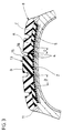
- FIG. 1 shows a pneumatic vehicle tire 1 with a carcass 2 which is wrapped around the bead cores 3 and a rubberized belt 4 which is arranged radially above the carcass 2 and which is composed of reinforcing elements 5.
- a tread 8 Above the belt 4 there is a tread 8 which has the areas A, B and C.
- the area A of the tread occupies a portion in the radial direction of the total tread thickness of approximately 60%.
- the tread 8 has a wing at its radially outer ends.
- the wing 11 has a rubber compound composition similar to that of the adjacent side walls 12.
- a possible compound composition for the individual areas of the tread 8 is listed in the table.
- the pphr unit relates to 100 parts by weight of rubber.
- the area B is designed such that it extends from the rubberized belt 5 into the surface 13 of the tread 8 coming into contact with the road.
- the area B of the tread 8 is separated from the area C of the tread 8 on both sides by a distance D of about 4 mm. Since the area C is in direct contact with the wing rubber compound 11 and this has excellent conductivity (approx. 10 4 ⁇ x cm), the electrostatic charge can be discharged, starting from the rim (not shown), onto which the pneumatic vehicle tire 1 is connected its beads 14 is mounted, take place via the electrically conductive side walls 12, the two wings 11 into the area C of the tread 8.
- the space formed by the distance D between the areas B and C is used to discharge the charge via the rubber coating of the belt 5. Since the specific electrical resistance of the belt rubber coating is approximately 10 6 ⁇ x cm, the distance D can be chosen to be relatively wide, since the rubber belt compensates this contact gap between the areas B and C sufficiently. In principle, the volume of the distance D can always be chosen so that the displaced rubber mixture of the area A through the area B is essentially in this space. As a result, the thickness of area A also plays a role. In Figure 1, this should be about 5 - 8 mm.
- the area B of the tread 8 covers in the central region of the surface of the tread coming into contact with the road all the way around z. B. about 2 to 4 mm. This has the advantage that the good properties of the tread compound A are not influenced and the conductivity is nevertheless increased and at the same time there are process engineering advantages in the production of the uncured tread.
- FIG. Another possibility is shown in FIG. in what way the areas A, B and C of the tread 8 can be designed.
- the areas A, B and C of the tread 8 can be designed.
- the middle of the tread 8 there are two conductive points in its surface 13 coming into contact with the road, which are formed by the area B of the tread 8, introduced.
- the area B a part of the with Surface 13 comes into contact with the road.
- Figure 2 illustrates that the Area B of the tread 8 can be shaped differently. So the one with area B in contact with the road has a greater extent have as the extension that is in contact with the rubber coating of the belt pact. With this design variant, road contact would be optimally secured.
- the area B can also have other shapes.
- the design of the areas A, B, C of the tread is also the distance D, so extrusion problems are optimized during the manufacture of the tread can.
- FIG. 3 shows the possibility that a tread block 15 of the tread 8 consists entirely of the tread compound of area B.
- the profile block 15 is again in the middle of the area that comes into contact with the road Surface 13 of the tread 8 and is delimited by two circumferential grooves.
- z. B. in one, as shown in Figure 3, four longitudinal grooves having profile of the middle tread block 15 from the conductive tread compound Area B exists to ensure safe contact with every load of the vehicle To achieve road surface.
- other profile blocks are equipped with the tread compound of area B. But is conceivable, for. B. also that only an axial limitation of area B the profile flank of a profile block forms. At least no more than 30% of the contact with the road coming surface consist of a rubber mixture of area B, so that Properties of the mixture of area A (good rolling resistance, wet slip behavior) of the entire tire is not lost.
- Area A has an excellent wet grip and low rolling resistance.
- Area B has excellent conductivity and also positive properties in Abrasion behavior and the area C is also highly conductive and can with respect to the Rolling resistance can be optimized.
- the distance D between the areas B and C is ensured in such a way that Fluctuations in quality that lead to poorer driving behavior are eliminated can be.
Landscapes
- Engineering & Computer Science (AREA)
- Mechanical Engineering (AREA)
- Tires In General (AREA)
- Transition And Organic Metals Composition Catalysts For Addition Polymerization (AREA)
Claims (11)
- Pneumatique (1) de véhicule comprenant une carcasse (2) qui s'étend depuis la zone des nappes au sommet du pneu jusqu'aux zones du talon, comprenant en outre une bande de roulement (8) et un ensemble de ceintures (4) caoutchouté et disposé entre la bande de roulement (8) et la carcasse (2),
caractérisé en ce que le gommage de l'ensemble de ceintures (4) a une résistance électrique spécifique < 108 Ω x cm, en ce que la bande de roulement (8) est constituée au moins de 3 zones, où la surface (13) de la bande de roulement (8) venant en contact avec la chaussée est constituée, sur plus de la moitié, d'une zone A de la bande de roulement (8) dont le mélange de caoutchouc a une résistance électrique spécifique > 1010 Ω x cm, lequel mélange de caoutchouc, dans le sens radial, comprend au moins 40 % de l'épaisseur totale de la bande de roulement et où la surface résiduelLe (13) venant en contact avec la chaussée est occupée, au moins partiellement, par une zone B dont le mélange de caoutchouc a une résistance électrique < 108 Ω x cm, où la zone B s'étend jusqu'à l'ensemble de ceintures (4) caoutchouté et où une zone C de la bande de roulement (8) dont le mélange de caoutchouc s'étend au-dessous de la zone A de la bande de roulement (8) et qui remplit l'espace important entre cette zone et l'ensemble de ceintures (4) et qui, au niveau de deux limitations axiales de la zone C, par rapport aux côtés du pneu, est en contact avec au moins un autre mélange de caoutchouc qui a une résistance spécifique < 108 Ω x cm, où la zone B de la bande de roulement (8) a par rapport à la section du pneu, au moins sur un côté, un espace D compris entre 1 mm et 30 mm par rapport à la zone C de la bande de roulement (8), où l'espace intermédiaire est rempli par le mélange de caoutchouc de la zone A de la bande de roulement (8). - Pneumatique (1) de véhicule selon la revendication 1,
caractérisé en ce que la zone B de la bande de roulement (8) a, par rapport à la section du pneu, un espace D compris entre 1 mm et 30 mm par rapport à la zone C, sur les deux côtés. - Pneumatique (1) de véhicule selon la revendication 1 ou 2, caractérisé en ce que l'espace D est compris entre 3 mm et 5 mm.
- Pneumatique (1) de véhicule selon au moins l'une quelconque des revendications précédentes, caractérisé en ce que les mélanges de caoutchouc des zones B et C ont la même résistance électrique spécifique.
- Pneumatique (1) de véhicule selon au moins l'une quelconque des revendications précédentes, caractérisé en ce que les mélanges de caoutchouc des zones B et C ont la même composition.
- Pneumatique (1) de véhicule selon au moins l'une quelconque des revendications précédentes, caractérisé en ce que le mélange de caoutchouc de la zone A est un mélange de caoutchouc contenant un gel de silice.
- Pneumatique (1) de véhicule selon au moins l'une quelconque des revendications précédentes, caractérisé en ce que les mélanges de caoutchouc des zones B et C contiennent principalement du noir de carbone servant de matière de remplissage.
- Pneumatique (1) de véhicule selon au moins l'une quelconque des revendications précédentes, caractérisé en ce que la zone B de la bande de roulement (8), dans la zone centrale, s'étend jusqu'à la surface (13) de la bande de roulement (8) venant en contact avec la chaussée.
- Pneumatique (1) de véhicule selon au moins l'une quelconque des revendications précédentes, caractérisé en ce que la zone B, au moins dans une zone d'épaulement, s'étend jusqu'à la surface (13) de la bande de roulement venant en contact avec la chaussée.
- Pneumatique (1) de véhicule selon au moins l'une quelconque des revendications précédentes, caractérisé en ce qu'au moins un bloc à sculptures (15) de la bande de roulement (8) se compose du mélange de caoutchouc de la zone B.
- Pneumatique (1) de véhicule selon au moins l'une quelconque des revendications précédentes, caractérisé en ce que la zone B de la bande de roulement (8) fait un contraste optique par rapport à la zone A de la bande de roulement (8).
Applications Claiming Priority (2)
| Application Number | Priority Date | Filing Date | Title |
|---|---|---|---|
| DE19644538A DE19644538C1 (de) | 1996-10-26 | 1996-10-26 | Fahrzeugluftreifen |
| DE19644538 | 1996-10-26 |
Publications (2)
| Publication Number | Publication Date |
|---|---|
| EP0838353A1 EP0838353A1 (fr) | 1998-04-29 |
| EP0838353B1 true EP0838353B1 (fr) | 2001-09-12 |
Family
ID=7810070
Family Applications (1)
| Application Number | Title | Priority Date | Filing Date |
|---|---|---|---|
| EP97118415A Expired - Lifetime EP0838353B1 (fr) | 1996-10-26 | 1997-10-23 | Bandage pneumatique pour véhicule |
Country Status (3)
| Country | Link |
|---|---|
| EP (1) | EP0838353B1 (fr) |
| AT (1) | ATE205446T1 (fr) |
| DE (2) | DE19644538C1 (fr) |
Cited By (1)
| Publication number | Priority date | Publication date | Assignee | Title |
|---|---|---|---|---|
| US8211258B2 (en) | 2006-04-05 | 2012-07-03 | Continental Aktiengesellschaft | Method and device for producing a tread for a vehicle tire |
Families Citing this family (13)
| Publication number | Priority date | Publication date | Assignee | Title |
|---|---|---|---|---|
| US5898047A (en) * | 1996-09-23 | 1999-04-27 | The Goodyear Tire & Rubber Company | Tire with outer carbon black reinforced rubber strip for static reduction |
| ES2259198T3 (es) | 1997-08-07 | 2006-09-16 | Bridgestone Corporation | Cubierta neumatica y metodo de fabricacion de la misma. |
| DE19812934C2 (de) * | 1998-03-24 | 2002-12-12 | Pirelli Reifenwerk Gmbh & Co K | Fahrzeugreifen mit einem Laufstreifen, der einen Cap-Bereich und einen Base-Bereich aufweist |
| DE19850766B4 (de) * | 1998-11-04 | 2004-01-22 | Continental Aktiengesellschaft | Fahrzeugluftreifen |
| JP2002096402A (ja) * | 2000-07-19 | 2002-04-02 | Bridgestone Corp | タイヤ用トレッドの製造方法 |
| US7819152B2 (en) * | 2005-02-15 | 2010-10-26 | The Goodyear Tire & Rubber Company | Pneumatic tire with tread having electrically conductive component underlying and extending through its tread |
| DE602006009085D1 (de) * | 2005-03-16 | 2009-10-22 | Bridgestone Corp | Luftreifen |
| DE102006032817A1 (de) * | 2006-07-14 | 2008-01-24 | Continental Aktiengesellschaft | Verfahren zur Herstellung eines Fahrzeugluftreifens und derart hergestellter Fahrzeugluftreifen |
| DE102006032818A1 (de) * | 2006-07-14 | 2008-01-24 | Continental Aktiengesellschaft | Verfahren zur Herstellung eines Fahrzeugluftreifens und derart hergestellter Fahrzeugluftreifen |
| JP5389868B2 (ja) * | 2011-07-26 | 2014-01-15 | 東洋ゴム工業株式会社 | 空気入りタイヤ |
| CN104364094B (zh) * | 2012-09-28 | 2017-04-26 | 横滨橡胶株式会社 | 充气轮胎 |
| KR101887809B1 (ko) * | 2017-05-11 | 2018-08-10 | 한국타이어 주식회사 | 접촉대전 자가발전모듈을 포함하는 타이어 |
| US11383561B2 (en) * | 2017-12-21 | 2022-07-12 | Compagnie Generale Des Etablissements Michelin | Crown architecture of an electrically conductive tire for a civil engineering vehicle |
Family Cites Families (6)
| Publication number | Priority date | Publication date | Assignee | Title |
|---|---|---|---|---|
| GB1255952A (en) * | 1968-01-12 | 1971-12-08 | Dunlop Holdings Ltd | Improvements in or relating to pneumatic tyres |
| IT1264990B1 (it) * | 1993-12-14 | 1996-10-17 | Pirelli | Pneumatico antistatico con mescole a basso tenore di nero di carbonio |
| GB9409453D0 (en) * | 1994-05-12 | 1994-06-29 | Sumitomo Rubber Ind | tyre tread and tyres incorporating them |
| DE4447823B4 (de) * | 1994-12-21 | 2007-07-26 | Dunlop Gmbh | Fahrzeugreifen und Verfahren zu seiner Herstellung |
| US6044882A (en) * | 1995-03-07 | 2000-04-04 | The Goodyear Tire & Rubber Company | Tire having silica reinforced rubber tread with outer cap containing carbon black |
| DE59600109D1 (de) * | 1996-03-29 | 1998-04-09 | Continental Ag | Fahrzeugluftreifen |
-
1996
- 1996-10-26 DE DE19644538A patent/DE19644538C1/de not_active Expired - Fee Related
-
1997
- 1997-10-23 AT AT97118415T patent/ATE205446T1/de not_active IP Right Cessation
- 1997-10-23 EP EP97118415A patent/EP0838353B1/fr not_active Expired - Lifetime
- 1997-10-23 DE DE59704589T patent/DE59704589D1/de not_active Expired - Lifetime
Cited By (1)
| Publication number | Priority date | Publication date | Assignee | Title |
|---|---|---|---|---|
| US8211258B2 (en) | 2006-04-05 | 2012-07-03 | Continental Aktiengesellschaft | Method and device for producing a tread for a vehicle tire |
Also Published As
| Publication number | Publication date |
|---|---|
| DE59704589D1 (de) | 2001-10-18 |
| DE19644538C1 (de) | 1998-09-03 |
| EP0838353A1 (fr) | 1998-04-29 |
| ATE205446T1 (de) | 2001-09-15 |
Similar Documents
| Publication | Publication Date | Title |
|---|---|---|
| EP0798142B1 (fr) | Bandage pneumatique pour véhicule | |
| EP0838353B1 (fr) | Bandage pneumatique pour véhicule | |
| DE3046716C3 (de) | Luftreifen für Fahrzeugräder | |
| DE2644452A1 (de) | Niederquerschnitt-luftreifen in guertelbauweise fuer schwerfahrzeuge | |
| EP0106838A2 (fr) | Pneumatique à carcasse radiale dont la portion de la bande de roulement consiste en une couche de base et une couche de couronne superposée | |
| EP3288781B1 (fr) | Pneumatique de véhicule muni d'une bande de roulement | |
| EP3288780B1 (fr) | Pneumatique de véhicule muni d'une bande de roulement | |
| EP2027991A1 (fr) | Procédé de fabrication d'un pneu de véhicule et pneu de véhicule | |
| DE2710446A1 (de) | Hochbelastbarer stahlkord-guertelreifen, insbesondere fuer lastwagen und andere schwer- oder grossfahrzeuge | |
| WO2015003825A1 (fr) | Pneumatique de véhicule | |
| EP3680114A1 (fr) | Pneumatique de véhicule | |
| EP3238958B1 (fr) | Pneu de véhicule utilitaire | |
| DE19850766B4 (de) | Fahrzeugluftreifen | |
| EP2594413B1 (fr) | Pneu de véhicule | |
| EP3325286B1 (fr) | Pneumatique de véhicule | |
| EP3362300B1 (fr) | Pneumatiques pour véhicules utilitaires | |
| EP0839675A1 (fr) | Bandage pneumatique pour véhicule | |
| EP3321109B1 (fr) | Pneumatique de véhicule | |
| EP0594045A1 (fr) | Bande de roulement d'un pneumatique pour véhicule | |
| DE102014102133B4 (de) | Luftreifen | |
| DE102013109355A1 (de) | Fahrzeugluftreifen | |
| EP3653402B1 (fr) | Pneumatiques de véhicule pourvu d'au moins un premier composant en caoutchouc et d'au moins un second composant en caoutchouc | |
| DE102024203193A1 (de) | Rollwiderstandsoptimierter Fahrzeugluftreifen mit verbesserten elektrischen Leitfähigkeitseigenschaften | |
| DE102023211054A1 (de) | Verfahren zum Herstellen eines Fahrzeugreifens und Fahrzeugreifen | |
| DE102023200172A1 (de) | Fahrzeugluftreifen |
Legal Events
| Date | Code | Title | Description |
|---|---|---|---|
| PUAI | Public reference made under article 153(3) epc to a published international application that has entered the european phase |
Free format text: ORIGINAL CODE: 0009012 |
|
| AK | Designated contracting states |
Kind code of ref document: A1 Designated state(s): AT BE DE FR GB IT LU NL |
|
| AX | Request for extension of the european patent |
Free format text: AL;LT;LV;SI |
|
| 17P | Request for examination filed |
Effective date: 19981029 |
|
| AKX | Designation fees paid |
Free format text: AT BE DE FR GB IT LU NL |
|
| RBV | Designated contracting states (corrected) |
Designated state(s): AT BE DE FR GB IT LU NL |
|
| 17Q | First examination report despatched |
Effective date: 20000621 |
|
| GRAG | Despatch of communication of intention to grant |
Free format text: ORIGINAL CODE: EPIDOS AGRA |
|
| GRAG | Despatch of communication of intention to grant |
Free format text: ORIGINAL CODE: EPIDOS AGRA |
|
| GRAH | Despatch of communication of intention to grant a patent |
Free format text: ORIGINAL CODE: EPIDOS IGRA |
|
| GRAH | Despatch of communication of intention to grant a patent |
Free format text: ORIGINAL CODE: EPIDOS IGRA |
|
| GRAA | (expected) grant |
Free format text: ORIGINAL CODE: 0009210 |
|
| AK | Designated contracting states |
Kind code of ref document: B1 Designated state(s): AT BE DE FR GB IT LU NL |
|
| PG25 | Lapsed in a contracting state [announced via postgrant information from national office to epo] |
Ref country code: NL Free format text: LAPSE BECAUSE OF FAILURE TO SUBMIT A TRANSLATION OF THE DESCRIPTION OR TO PAY THE FEE WITHIN THE PRESCRIBED TIME-LIMIT Effective date: 20010912 Ref country code: IT Free format text: LAPSE BECAUSE OF FAILURE TO SUBMIT A TRANSLATION OF THE DESCRIPTION OR TO PAY THE FEE WITHIN THE PRE;WARNING: LAPSES OF ITALIAN PATENTS WITH EFFECTIVE DATE BEFORE 2007 MAY HAVE OCCURRED AT ANY TIME BEFORE 2007. THE CORRECT EFFECTIVE DATE MAY BE DIFFERENT FROM THE ONE RECORDED.SCRIBED TIME-LIMIT Effective date: 20010912 Ref country code: GB Free format text: LAPSE BECAUSE OF FAILURE TO SUBMIT A TRANSLATION OF THE DESCRIPTION OR TO PAY THE FEE WITHIN THE PRESCRIBED TIME-LIMIT Effective date: 20010912 Ref country code: FR Free format text: LAPSE BECAUSE OF FAILURE TO SUBMIT A TRANSLATION OF THE DESCRIPTION OR TO PAY THE FEE WITHIN THE PRESCRIBED TIME-LIMIT Effective date: 20010912 |
|
| REF | Corresponds to: |
Ref document number: 205446 Country of ref document: AT Date of ref document: 20010915 Kind code of ref document: T |
|
| REF | Corresponds to: |
Ref document number: 59704589 Country of ref document: DE Date of ref document: 20011018 |
|
| PG25 | Lapsed in a contracting state [announced via postgrant information from national office to epo] |
Ref country code: LU Free format text: LAPSE BECAUSE OF NON-PAYMENT OF DUE FEES Effective date: 20011023 Ref country code: AT Free format text: LAPSE BECAUSE OF NON-PAYMENT OF DUE FEES Effective date: 20011023 |
|
| PG25 | Lapsed in a contracting state [announced via postgrant information from national office to epo] |
Ref country code: BE Free format text: LAPSE BECAUSE OF NON-PAYMENT OF DUE FEES Effective date: 20011031 |
|
| NLV1 | Nl: lapsed or annulled due to failure to fulfill the requirements of art. 29p and 29m of the patents act | ||
| GBV | Gb: ep patent (uk) treated as always having been void in accordance with gb section 77(7)/1977 [no translation filed] |
Effective date: 20010912 |
|
| BERE | Be: lapsed |
Owner name: CONTINENTAL A.G. Effective date: 20011031 |
|
| PLBQ | Unpublished change to opponent data |
Free format text: ORIGINAL CODE: EPIDOS OPPO |
|
| PLBI | Opposition filed |
Free format text: ORIGINAL CODE: 0009260 |
|
| PLBF | Reply of patent proprietor to notice(s) of opposition |
Free format text: ORIGINAL CODE: EPIDOS OBSO |
|
| EN | Fr: translation not filed | ||
| 26 | Opposition filed |
Opponent name: SUMITOMO RUBBER INDUSTRIES, LTD. PATENT DEPARTMENT Effective date: 20020612 |
|
| PLBF | Reply of patent proprietor to notice(s) of opposition |
Free format text: ORIGINAL CODE: EPIDOS OBSO |
|
| PLBP | Opposition withdrawn |
Free format text: ORIGINAL CODE: 0009264 |
|
| PLBL | Opposition procedure terminated |
Free format text: ORIGINAL CODE: EPIDOS OPPC |
|
| PLBM | Termination of opposition procedure: date of legal effect published |
Free format text: ORIGINAL CODE: 0009276 |
|
| STAA | Information on the status of an ep patent application or granted ep patent |
Free format text: STATUS: OPPOSITION PROCEDURE CLOSED |
|
| 27C | Opposition proceedings terminated |
Effective date: 20030405 |
|
| PGFP | Annual fee paid to national office [announced via postgrant information from national office to epo] |
Ref country code: DE Payment date: 20151031 Year of fee payment: 19 |
|
| REG | Reference to a national code |
Ref country code: DE Ref legal event code: R119 Ref document number: 59704589 Country of ref document: DE |
|
| PG25 | Lapsed in a contracting state [announced via postgrant information from national office to epo] |
Ref country code: DE Free format text: LAPSE BECAUSE OF NON-PAYMENT OF DUE FEES Effective date: 20170503 |