EP0838545A2 - Strickwerkzeug für Textilmaschinen und Herstellungsverfahren für dieses - Google Patents
Strickwerkzeug für Textilmaschinen und Herstellungsverfahren für dieses Download PDFInfo
- Publication number
- EP0838545A2 EP0838545A2 EP97116773A EP97116773A EP0838545A2 EP 0838545 A2 EP0838545 A2 EP 0838545A2 EP 97116773 A EP97116773 A EP 97116773A EP 97116773 A EP97116773 A EP 97116773A EP 0838545 A2 EP0838545 A2 EP 0838545A2
- Authority
- EP
- European Patent Office
- Prior art keywords
- knitting
- embossing
- blank
- needle
- edge
- Prior art date
- Legal status (The legal status is an assumption and is not a legal conclusion. Google has not performed a legal analysis and makes no representation as to the accuracy of the status listed.)
- Granted
Links
- 238000009940 knitting Methods 0.000 title claims abstract description 50
- 238000004519 manufacturing process Methods 0.000 title claims abstract description 14
- 238000000034 method Methods 0.000 title claims description 25
- 239000004753 textile Substances 0.000 title claims 4
- 238000004049 embossing Methods 0.000 claims abstract description 44
- 238000012545 processing Methods 0.000 claims abstract description 31
- 239000000463 material Substances 0.000 claims abstract description 13
- 238000003754 machining Methods 0.000 claims abstract description 10
- 238000007493 shaping process Methods 0.000 claims abstract description 5
- 239000011265 semifinished product Substances 0.000 claims abstract description 3
- 230000007704 transition Effects 0.000 claims description 12
- 238000005520 cutting process Methods 0.000 claims description 6
- 238000000465 moulding Methods 0.000 claims description 3
- 229910000831 Steel Inorganic materials 0.000 abstract description 5
- 238000003801 milling Methods 0.000 abstract description 5
- 239000010959 steel Substances 0.000 abstract description 5
- 238000000748 compression moulding Methods 0.000 abstract description 4
- 230000008901 benefit Effects 0.000 abstract description 3
- 238000007711 solidification Methods 0.000 abstract description 3
- 230000008023 solidification Effects 0.000 abstract description 3
- 238000004080 punching Methods 0.000 description 12
- 210000000038 chest Anatomy 0.000 description 4
- 210000000481 breast Anatomy 0.000 description 3
- 230000015572 biosynthetic process Effects 0.000 description 2
- 238000000227 grinding Methods 0.000 description 2
- 238000005498 polishing Methods 0.000 description 2
- 230000001154 acute effect Effects 0.000 description 1
- 238000007596 consolidation process Methods 0.000 description 1
- 238000005336 cracking Methods 0.000 description 1
- 238000006073 displacement reaction Methods 0.000 description 1
- 238000007688 edging Methods 0.000 description 1
- 210000001061 forehead Anatomy 0.000 description 1
- 210000003128 head Anatomy 0.000 description 1
- 239000000314 lubricant Substances 0.000 description 1
- 239000002184 metal Substances 0.000 description 1
- 230000035515 penetration Effects 0.000 description 1
- 238000012805 post-processing Methods 0.000 description 1
- 238000002360 preparation method Methods 0.000 description 1
- 239000002689 soil Substances 0.000 description 1
Images




Classifications
-
- D—TEXTILES; PAPER
- D04—BRAIDING; LACE-MAKING; KNITTING; TRIMMINGS; NON-WOVEN FABRICS
- D04B—KNITTING
- D04B35/00—Details of, or auxiliary devices incorporated in, knitting machines, not otherwise provided for
- D04B35/02—Knitting tools or instruments not provided for in group D04B15/00 or D04B27/00
-
- B—PERFORMING OPERATIONS; TRANSPORTING
- B21—MECHANICAL METAL-WORKING WITHOUT ESSENTIALLY REMOVING MATERIAL; PUNCHING METAL
- B21G—MAKING NEEDLES, PINS OR NAILS OF METAL
- B21G1/00—Making needles used for performing operations
- B21G1/06—Making needles used for performing operations of needles with hook or barb, e.g. crochet hooks
Definitions
- the invention relates to processes for the production of Knitting tools using a punched blank (Blank) is assumed.
- the Invention a punched knitting tool with rounded, beveled or broken edges.
- latch needles there are latch needles, point needles, sliding needles, Needles without tongue, for example plush hooks for manufacturing of plush goods, as well as boards and the like understand.
- the knitting tools mentioned are usually large To produce a number of pieces of consistently good quality. This particularly affects the edges of the knitting tools, in contact with the thread to be knitted come or that with channel walls corresponding guide or Needle channels are in contact and related these are moved.
- the needle foot in one Embossing processing step with groove-like depressions or grooves that extend over the entire length extend the needle foot over its flat sides.
- One too stamping tool created for this purpose takes the foot of the raw-punched needle from a steel band and presses when closing in the flat sides of the needle foot the mentioned wells. Die when punching out the Needlefoot's previously created fracture surfaces become squeezed outwards and converted into a predetermined shape. The rest of the needle is not from the embossing process affected.
- DE 44 42 943 C1 is a punched knitting tool known that a shaft with plastic-filled Has openings.
- the marginal edges of both sides of the Openings are crimped to form a positive To enable attachment of the plastic filling.
- the edges are squeezed from both sides the flat strip-shaped shaft towards each other pressed, causing the material flowing towards each other the wall of the slit-shaped opening is deformed. Between the so bevelled opening edges is the Diaphragm wall concave.
- Knitting tool and a method to create themselves in the manufacture of knitting tools, machining edges Avoid or remove burrs.
- edge areas before or after another shaping process such as milling or punching by means of embossing, rounded, chamfered or otherwise broken.
- claim 1 is one by punching out the blank resulting sharp edge or a corresponding one Burr removed by embossing.
- the punch blank into the engraving of a corresponding embossing tool laid and shaped in it.
- the engraving that is the Receiving space of the embossing tool for the blank, is dimension so that protruding or sharp edges of the blank to be pressed in, being in the edge area a flow of material towards the center of the blank is obtained.
- the edge area and the subsequent, also affected by the forming process Surface areas are solidified. This can improve the durability of a needle made in this way.
- the geometry of the Knitting tool set relatively precisely.
- the cross section the knitting tool is based on the shape of the engraving of the embossing tool defines and agrees with this.
- inclined surfaces or facets are formed.
- the one obtained by embossing Edge geometry enables significantly improved Sliding properties of the faceted knitting tools in corresponding guide channels of knitting or knitting machines. Compared to conventional polishing or grinding processes to remove machining burrs with the molding process step is more reproducible Contours reached.
- the knitting tools tend less to damage channel walls and displace that Less lubricant.
- the embossing tool preferably takes the entire blank, so that it is shaped overall becomes. This will become the later knitting tool, if present, also in the area of his foot, surface hardened and deburred at the same time.
- the blank can be punched also give a shape to the damage the one to be knitted with the knitting tool Excludes thread.
- the stamping processing step can both, as mentioned above, after punching out the Stamped blanks are run to existing sharp ones Blunt edges, as well as before a cutting Processing step. This is, for example, during production of latch needles of importance in which in the A needle slit to accommodate a movable stored tongue must be trained.
- the slot will usually milled into the blank in question, with sharp edges at the edge of the milled slot arise.
- the method according to the invention is previously embossed at least one obliquely flanked groove into the blank. The groove bottom is the next Milling process deepened, after which a breakthrough is formed can be.
- the embossing processing step can be on two each other opposite narrow sides of the needle blank be executed so that the slot to be trained has rounded edges on both sides.
- the embossing processing step can be done with two dies as well as with correspondingly profiled ones Roles are performed. These are then mechanical or electronically guided on curves or they are with a predetermined force pressed against the blank ⁇ whereby the desired depth of penetration is automatic sets.
- the embossing direction that is the Direction in the area of the bevelled edges mainly material is moved in both cases aligned approximately to the center of the cross section.
- a punched knitting tool has on its outer contour especially at least one in the edge area Embossing area that is free of sharp edges. Form the embossing areas or the outer edges of the Knitting tool, runs a corresponding knitting tool low-friction in assigned guide channels and treated Threads to be processed gently in the thread sliding area.
- a knitting tool serving tongue needle 1 each has a head or Hook 2, which is followed by a neck 3, which in a needle breast 4 passes over.
- a longitudinal slot 6 In their area is a arranged longitudinal slot 6, for example, in which a needle tongue 7 is pivotable about a bearing 8 is arranged stored.
- the needle breast 4 is connected via a throat 9 a shaft 11, which when using the needle in a Needle channel of a knitting machine is added.
- the one with Shaft 11 provided with a plurality of recesses 12 instructs its end 13 remote from the hook 2 has a foot 14 on.
- the foot 14 is formed in one piece on the shaft 11 and extends at right angles to the longitudinal direction 16 the latch needle 1.
- the foot 14 goes with it arcuate transitions 17, 18 in the shaft 11.
- the latch needle 1 has two mutually parallel Flat sides 21, 22, between which narrow sides, namely Needle top 23 and needle back 24. How 3 shows are between the top of the needle 23 and the flanks 21, 22 transition regions 26, 27 are provided, which are somewhat rounded and therefore not sharp-edged Form transition. Corresponding transition areas 28, 29 are between the needle back 24 and the lateral flanks or flat sides 21, 22 are provided.
- the longitudinal slot 6 is on the top of the needle 23 lying mouth of inclined flanks 31, 32 limited that without sharp edges in the top of the needle 23 pass over.
- Corresponding inclined flanks 54, 55 can on the underside in the transition to the needle back 24 be provided.
- a Fig. 2 illustrated punch blank 33, the has been punched out of a thin steel strip. His Outer contour, that is its outline 34, is due to that Stamping tool essentially set. To the outer contour 34 include both the flanks 21, 22 (Fig. 4) as also the needle top 23 and the needle back 24. After the punching of the punch blank 33 from the steel strip this with respect to its parallel to the flat sides 21, 22 The longitudinal center plane 36 is initially asymmetrical. While on the upper side in FIG. 4 along the contour 34 of the blank 33 ridges 37 are formed is his Feed side 38 (bottom in Fig. 4) rounded. The in between Fractures 39 are uneven and mostly not exactly at right angles to the flat sides 21, 22.
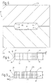
- At least the ridge 37, which is about the ridge height G rises above the flat side 22 to remove is an in Fig. 6 illustrated embossing tool 41 provided that from an upper tool 41a and a lower tool 41b exists and with which the punch blank 33 in an embossing blank 33a is transferred.
- One in the embossing tool 41 trained engraving 42 corresponds in shape to that machined embossing blank 33a, from which the base body the latch needle 1 is formed.
- the light inner Width W of the engraving 42 of the embossing tool 41 is the same closed stamping tool 41 with the thickness D of the blank 33 matches or is at most insignificant less.
- a corresponding edge deformation of the punch blank 33 can be reached in the upper tool 41a and the lower tool 41b at the edges of the engraving 42 rounded edge regions 44, 45, 46, 47 are formed. Otherwise, the engraving 42 is limited by flat surfaces.
- a punch blank 33 inserted into the engraving 42 is therefore in particular when closing the embossing tool 41 deformed in the area of its outer edges, its Thickness D remains essentially unchanged.
- the punch blank 33 is related to that shown in FIG the longitudinal center plane 36 is essentially symmetrical Form (embossing blank 33a with outer contour 34a) transferred.
- Both the ridges 37 and the feed side 38 are performed in the embossing tool 41 Shape embossing process deformed, the transition areas 26, 27, 28, 29 have been formed with radii that predetermined by the edge areas 44 to 47 of the engraving 42 are.
- the material flow direction is based on the 4 and 5 illustrated cross-sectional area about diagonally to the center of the cross section.
- a stronger deformation of the punch blank 33, at the fracture surfaces 39 by flowing the material can be smoothed is possible. Be independent of it defined by the embossing process rounded or beveled edge areas reached that are solidified. This applies both to edges in the thread sliding area of the neck 3, the needle chest 4 and the throat 9 as well as for the edges of the shaft 11.
- the edge rounding in the thread sliding area improves the properties the latch needle 1 in terms of treatment a thread during the knitting process.
- the rounding the edges of the shaft improve the running properties the latch needle 1 in the needle channel.
- the surface hardening achieved is an advantage in both cases.
- the stamping processing step in particular the dynamic strength of the foot 14 positive influenced. This is achieved by in the stamping processing step especially the arched transitions 17, 18 shaped between shaft 11 and foot 14 will.
- the surfaces and edges in question continuously smoothed or rounded, so that the foot 14 is able to cope with higher dynamic continuous loads.
- the shape embossing process becomes microscopic surface irregularities eliminated and the surface is particularly in the Area of transitions 17, 18 smoothed.
- the blank is embossed 33a of the longitudinal slot 6 is formed.
- delimiting Edging is used in the manufacture of the latch needle 1 Needle chest 4 die stamping processing step inserted.
- the longitudinal slot 6 shown in FIG. 8 is in its central area by parallel to each other Slotted edges 51, 52 delimited, on the top of the needle 23 of the latch needle 1, the oblique flanks 31, 32 connect to this.
- the needle back 24 inclined flanks 54, 55 formed which like that Sloping flanks 31, 32 together form an acute angle ⁇ include, for example, 60 °.
- the plan trained in the example Sloping flanks 31, 32; 54, 55 can also be rounded and arranged at a different angle to each other be.
- Figs. 7 and 9 illustrated dies 57, 58. While the upper die 57 in its Longitudinal direction of curvature of the embossing blank 33a in the area the neck 3 and the needle breast 4 is adapted, it has a trapezoidal cross-section with a narrow forehead 59, the width of which is somewhat smaller than the distance of the slot flanks 51, 52 from each other. The corresponding lower die 58 is in cross section also trapezoidal, but the Needle back 24 is correspondingly straight.
- the stamping dies 57, 58 towards the embossing blank 33a held between them moves so that they both on the needle top 23 also on the needle back 24 each in cross section trapezoidal longitudinal groove 61, 62 in the embossing blank 33 mold.
- the transition to the needle top 23 and the edges 63, 64 of the needle back 24 not sharp, but rather rounded.
- the Outer contour 34a is including the outer one Transitional areas 26, 27, 28, 29 and edges 63, 64 exclusively defined by non-cutting processing steps.
- the in 10 illustrates rollers 71, 72 for use come. These point to their respective outside trapezoidal profile.
- the longitudinal groove 61, 62 becomes the blank 33, 33a between the rollers 71, 72 carried out that this in the top of the needle 23 and push in the needle back 24, or the rollers 71, 72 are guided along the blank 33, 33a.
- the roller 72 moves on a straight path 73, while the roller 71 on a corresponding to the needle contour curved path 74 is guided.
Landscapes
- Engineering & Computer Science (AREA)
- Textile Engineering (AREA)
- Mechanical Engineering (AREA)
- Knitting Machines (AREA)
- Punching Or Piercing (AREA)
- Shaping Metal By Deep-Drawing, Or The Like (AREA)
Abstract
Description
- Fig. 1
- eine Zungennadel in einer schematisierten Seitenansicht,
- Fig. 2
- einen Rohling zur Herstellung einer Zungennadel nach Fig. 1, in einer schematisierten Seitenansicht,
- Fig. 3
- eine im Nadelbrustbereich geschnittene Zungennadel in ausschnittsweiser, vereinfachter Darstellung,
- Fig. 4
- einen Stanzrohling (ausgestanzter Rohling) vor einem späteren Formprägebearbeitungsschritt, in schematisierter Darstellung, im Querschnitt,
- Fig. 5
- den Prägerohling (formgeprägter Rohling nach Fig. 2), in einer schematischen Darstellung, im Querschnitt,
- Fig. 6
- ein Prägewerkzeug zur Durchführung eines Formprägebearbeitungsschrittes an dem Stanzrohling nach Fig. 4, in schematisierter Darstellung, im Querschnitt,
- Fig. 7
- den Rohling nach Fig. 2 vor Ausbildung des Längsschlitzes und nach einem Formprägebearbeitungsschritt, in schematisierter Darstellung, im Querschnitt und in einem anderen Maßstab,
- Fig. 8
- den Rohling nach Fig. 7, versehen mit einem Längsschlitz im Nadelbrustbereich, in einer schematisierten Darstellung, im Querschnitt, in einem anderen Maßstab,
- Fig. 9
- eine Vorrichtung zur Durchführung eines Formprägebearbeitungsschrittes an einem Rohling für eine Zungennadel, in Seitenansicht, in stark schematisierter Darstellung, und
- Fig. 10
- eine alternative Vorrichtung zur Durchführung des Formprägebearbeitungsschrittes an einem Rohling für eine Zungennadel, in schematisierter Darstellung, in einer Seitenansicht.
Claims (10)
- Verfahren zur Herstellung von Strickwerkzeugen (1) für Textilmaschinen, insbesondere Wirk- oder Strickmaschinen, bei dem aus einem Halbzeug ein Stanzrohling (33) ausgestanzt wird und bei dem zumindest ein an der Außenkontur (34) entstandener scharfer Grat (37) oder eine scharfe Kante (38) wenigstens abschnittsweise verrundet oder angeschrägt wird,
dadurch gekennzeichnet,
daß zum Verrunden oder Anschrägen des Grates (37) und/oder der Kante (38) der Außenkontur (34) ein Formprägebearbeitungsschritt durchgeführt wird, bei dem der Grat (37) und/oder die scharfe Kante (38) durch Prägen ganz oder abschnittsweise beseitigt werden. - Verfahren nach Anspruch 1, dadurch gekennzeichnet, daß bei dem Formprägebearbeitungsschritt außerdem Bereiche (21, 22, 23, 24) geprägt werden, die dem anzuschrägenden Bereich (26, 27, 28, 29) benachbart sind.
- Verfahren nach Anspruch 1, dadurch gekennzeichnet, daß der Stanzrohling (33) bei dem Formprägebearbeitungsschritt in einen Prägerohling (33a) überführt wird, dessen Querschnittskontur von dem Prägewerkzeug (41) bestimmt wird.
- Verfahren nach Anspruch 1, dadurch gekennzeichnet, daß der Grat (37) und/oder die Kante (38) bei dem Formprägebearbeitungsschritt in Richtung auf die Mitte des Querschnitts hin deformiert wird und der Materialfluß in diesem Bereich in dieser Richtung erfolgt, wobei eine im wesentlichen konvexe Querschnittsgestalt ausgebildet wird.
- Verfahren zur Herstellung von Strickwerkzeugen (1) für Textilmaschinen, insbesondere Wirk- oder Strickmaschinen, bei dem an einem Rohling (33, 33a) in einem spanabhebenden Bearbeitungsschritt eine Vertiefung oder ein Schlitz (6) mit einer diesen berandenden Kante (31, 32) ausgebildet wird
dadurch gekennzeichnet,
daß zum Verrunden oder Anschrägen der Kante (31, 32) des Schlitzes (6) vor dem spanabhebenden Bearbeitungsschritt ein Formprägebearbeitungsschritt durchgeführt wird, bei dem in dem Rohling (33, 33a) zunächst eine Nut (61) mit wenigstens abschnittsweise schrägen oder verrundeten Flanken (31, 32) ausgebildet wird. - Verfahren nach Anspruch 5, dadurch gekennzeichnet, daß die spanlos ausgebildete Nut (61) bei der spanabhebenden Bearbeitung zumindest vertieft wird, so daß sich an die Flanken der Nut (61) anschließende, zueinander parallele, aufeinander zu weisende Wände (51, 52) erzeugt werden.
- Verfahren nach Anspruch 5, dadurch gekennzeichnet, daß die Nut (61) mittels wenigstens eines Prägestempels (57) oder einer entsprechend profilierten Rolle (71) ausgebildet wird.
- Gestanztes Strickwerkzeug (1) für Textilmaschinen, insbesondere Wirk- oder Strickmaschinen, mit einem durch ein Stanzteil gebildeten Grundkörper, der wenigstens an seiner Außenkontur (34a) einen Prägebereich (26, 27, 28, 29, 31, 32, 54, 55) aufweist.
- Strickwerkzeug nach Anspruch 8, dadurch gekennzeichnet, daß es einen flachen Schaft (11) und einen einstückig daran ausgebildeten Fuß (14) aufweist, die jeweils zwei zueinander parallele Flachseiten (21, 22) und diese verbindende Schmalseiten (23, 24) aufweisen, daß die Prägebereiche (26, 27, 28, 29) im Übergang zwischen den Schmalseiten (23, 24) und den Flachseiten (21, 22) ausgebildet sind und daß zwischen dem Schaft (11) und dem sich im wesentlichen rechtwinklig zu diesem erstreckenden Fuß (14) ein Übergangsbereich (17, 18) vorgesehen ist, dessen Kanten durch die Prägebereiche definiert sind.
- Strickwerkzeug nach Anspruch 8, dadurch gekennzeichnet, daß das Strickwerkzeug (1) wenigstens einen Kopfbereich mit einem Schlitz (6) aufweist und daß der Prägebereich (31, 32) an dem Schlitz (6) vorgesehen ist und wenigstens abschnittsweise dessen Berandung bildet.
Applications Claiming Priority (2)
| Application Number | Priority Date | Filing Date | Title |
|---|---|---|---|
| DE19644166A DE19644166C1 (de) | 1996-10-24 | 1996-10-24 | Strickwerkzeug für Textilmaschinen und Herstellungsverfahren für dieses |
| DE19644166 | 1996-10-24 |
Publications (3)
| Publication Number | Publication Date |
|---|---|
| EP0838545A2 true EP0838545A2 (de) | 1998-04-29 |
| EP0838545A3 EP0838545A3 (de) | 1999-04-21 |
| EP0838545B1 EP0838545B1 (de) | 2003-03-19 |
Family
ID=7809836
Family Applications (1)
| Application Number | Title | Priority Date | Filing Date |
|---|---|---|---|
| EP97116773A Expired - Lifetime EP0838545B1 (de) | 1996-10-24 | 1997-09-26 | Strickwerkzeug für Textilmaschinen und Herstellungsverfahren für dieses |
Country Status (5)
| Country | Link |
|---|---|
| US (1) | US6112556A (de) |
| EP (1) | EP0838545B1 (de) |
| JP (1) | JP3305635B2 (de) |
| DE (2) | DE19644166C1 (de) |
| ES (1) | ES2195064T3 (de) |
Families Citing this family (5)
| Publication number | Priority date | Publication date | Assignee | Title |
|---|---|---|---|---|
| DE102005028099B3 (de) * | 2005-06-16 | 2007-03-15 | Hugo Kern Und Liebers Gmbh & Co. Kg Platinen- Und Federnfabrik | Verfahren zum Herstellen von Nadeln für Textilmaschinen sowie danach hergestellte Nadeln |
| CN100402225C (zh) * | 2005-12-05 | 2008-07-16 | 秦策 | 钢丝横机针后缺免铣加工方法 |
| CN102105628B (zh) * | 2008-07-23 | 2012-06-27 | 株式会社岛精机制作所 | 编织针驱动用三角及横编机 |
| US9371603B2 (en) * | 2013-02-28 | 2016-06-21 | Nike, Inc. | Feeder for knitting machine with friction reducing features |
| CN115976726A (zh) * | 2023-02-20 | 2023-04-18 | 常熟宣驰经编机配件有限公司 | 一种经编机用的织针及其加工方法 |
Family Cites Families (9)
| Publication number | Priority date | Publication date | Assignee | Title |
|---|---|---|---|---|
| DE2123971A1 (de) * | 1970-05-20 | 1971-12-02 | Vyzkumny ustav pletarzsky, Brunn (Tschechoslowakei) | Arbeitselement einer Strickmaschine mit mindestens einem Nadelfuß |
| US4036036A (en) * | 1976-03-22 | 1977-07-19 | The Torrington Company | Latch needle for knitting machines |
| DE2637078C3 (de) * | 1976-08-18 | 1981-12-17 | Willy 7474 Bitz Zimmermann | Verfahren und Vorrichtung zur Bearbeitung des Fußes von gestanzten Strick- oder Wirkmaschinennadeln bzw. von Platinen, Nadelschiebern, Stößern o.dgl. |
| DE2911195C2 (de) * | 1979-03-22 | 1981-03-19 | Theodor Groz & Söhne & Ernst Beckert Nadelfabrik KG, 7470 Albstadt | Verfahren zur Bearbeitung der Nadelfüße gestanzter Strickmaschinennadeln |
| DE3401874A1 (de) * | 1984-01-20 | 1985-07-25 | Haase & Kühn S.A., Les Geneveys, Coffrane | Umhaengenadel und verfahren zu ihrer herstellung |
| DE8913293U1 (de) * | 1989-11-10 | 1989-12-28 | Theodor Groz & Söhne & Ernst Beckert Nadelfabrik KG, 7470 Albstadt | Gestanztes Strickwerkzeug für Textilmaschinen |
| JPH04263658A (ja) * | 1991-02-18 | 1992-09-18 | Fukuhara Seiki Seisakusho:Kk | 編機用編針 |
| DE4402706C1 (de) * | 1994-01-29 | 1995-06-08 | Groz & Soehne Theodor | Zungennadel für Textilmaschinen |
| DE4442943C1 (de) * | 1994-12-02 | 1996-05-15 | Groz & Soehne Theodor | Gestanztes Strickwerkzeug für Textilmaschinen, insbesondere Wirk- oder Strickmaschinen |
-
1996
- 1996-10-24 DE DE19644166A patent/DE19644166C1/de not_active Expired - Fee Related
-
1997
- 1997-09-26 DE DE59709552T patent/DE59709552D1/de not_active Expired - Lifetime
- 1997-09-26 ES ES97116773T patent/ES2195064T3/es not_active Expired - Lifetime
- 1997-09-26 EP EP97116773A patent/EP0838545B1/de not_active Expired - Lifetime
- 1997-10-23 JP JP29066097A patent/JP3305635B2/ja not_active Expired - Fee Related
- 1997-10-23 US US08/956,778 patent/US6112556A/en not_active Expired - Lifetime
Also Published As
| Publication number | Publication date |
|---|---|
| DE19644166C1 (de) | 1997-11-20 |
| EP0838545A3 (de) | 1999-04-21 |
| DE59709552D1 (de) | 2003-04-24 |
| EP0838545B1 (de) | 2003-03-19 |
| US6112556A (en) | 2000-09-05 |
| ES2195064T3 (es) | 2003-12-01 |
| JPH10128458A (ja) | 1998-05-19 |
| JP3305635B2 (ja) | 2002-07-24 |
Similar Documents
| Publication | Publication Date | Title |
|---|---|---|
| DE4316012C2 (de) | Verfahren zur Feinbearbeitung von Werkstück-Oberflächen | |
| DE69518288T2 (de) | Verfahren zur Herstellung einer chirurgischen Nadel | |
| AT401901B (de) | Gerät zum schneiden von haaren mit einer zahnschneideinrichtung und verfahren zum herstellen eines messers für eine zahnschneideinrichtung eines solchen gerätes | |
| DE60204973T2 (de) | Verfahren zur herstellung einer innenklinge für einen elektrischen rasierapparat | |
| DE102007005847A1 (de) | Kettenrad aus Stahlblech und Verfahren zur Herstellung eines Kettenrads aus Stahlblech | |
| EP1616652A2 (de) | Werkzeug zur spanlosen Fertigerzeugung eines vorerzeugten Gewindes, Verfahren zur Herstellung eines derartigen Werkzeugs und Verfahren zur Erzeugung eines Gewindes | |
| DE2811567A1 (de) | Bohrschraube sowie verfahren und vorrichtung zu ihrer herstellung | |
| DE2650801A1 (de) | Verfahren zum anformen eines kopfes und danach hergestelltes erzeugnis | |
| DE2732095C2 (de) | ||
| DE102009029756B4 (de) | Verfahren zur Herstellung von Stanzteilen, insbesondere von Synchronringen, Kupplungskörpern oder Kupplungsscheiben | |
| DE102017123786A1 (de) | Halter für ein Nutstoßwerkzeug | |
| EP0838545B1 (de) | Strickwerkzeug für Textilmaschinen und Herstellungsverfahren für dieses | |
| DE60116795T2 (de) | Werkstück,schubtreibriemen und verfahren und werkzeug dafür | |
| EP0061184B1 (de) | Verfahren zur Herstellung von Nähmaschinennadeln | |
| DE102010061991A1 (de) | Verfahren zum Stanzen einer aus Fasermaterial bestehenden Fasermatte | |
| DE2144058B2 (de) | Filznadel | |
| DE2518066A1 (de) | Filznadel | |
| EP3266919B1 (de) | Filznadel und verfahren zum herstellen zumindest einer filznadel | |
| DE602004011154T2 (de) | Verfahren zur schleiflosen Herstellung einer chirurgischen Nadel | |
| DE2732096A1 (de) | Verfahren zur herstellung von naehmaschinennadeln | |
| EP0890668B1 (de) | Gestanztes Strickwerkzeug für Textilmaschinen, insbesondere Strick- und Wirkmaschinen | |
| EP2610019A1 (de) | Werkzeugmatrize für eine Werkzeugeinheit | |
| DE3414262C2 (de) | ||
| DE1952152A1 (de) | Verfahren zur Herstellung von Naehmaschinennadeln | |
| DE602004012451T2 (de) | Geteiltes formwerkzeug mit mindestens zwei formwerkzeugkomponenten |
Legal Events
| Date | Code | Title | Description |
|---|---|---|---|
| PUAI | Public reference made under article 153(3) epc to a published international application that has entered the european phase |
Free format text: ORIGINAL CODE: 0009012 |
|
| AK | Designated contracting states |
Kind code of ref document: A2 Designated state(s): DE ES GB IT |
|
| AX | Request for extension of the european patent |
Free format text: AL;LT;LV;RO;SI |
|
| PUAL | Search report despatched |
Free format text: ORIGINAL CODE: 0009013 |
|
| AK | Designated contracting states |
Kind code of ref document: A3 Designated state(s): AT BE CH DE DK ES FI FR GB GR IE IT LI LU MC NL PT SE |
|
| AX | Request for extension of the european patent |
Free format text: AL;LT;LV;RO;SI |
|
| 17P | Request for examination filed |
Effective date: 19991004 |
|
| AKX | Designation fees paid |
Free format text: DE ES GB IT |
|
| 17Q | First examination report despatched |
Effective date: 20010927 |
|
| GRAH | Despatch of communication of intention to grant a patent |
Free format text: ORIGINAL CODE: EPIDOS IGRA |
|
| GRAH | Despatch of communication of intention to grant a patent |
Free format text: ORIGINAL CODE: EPIDOS IGRA |
|
| GRAA | (expected) grant |
Free format text: ORIGINAL CODE: 0009210 |
|
| AK | Designated contracting states |
Designated state(s): DE ES GB IT |
|
| REG | Reference to a national code |
Ref country code: GB Ref legal event code: FG4D Free format text: NOT ENGLISH |
|
| GBT | Gb: translation of ep patent filed (gb section 77(6)(a)/1977) |
Effective date: 20030319 |
|
| REF | Corresponds to: |
Ref document number: 59709552 Country of ref document: DE Date of ref document: 20030424 Kind code of ref document: P |
|
| PLBE | No opposition filed within time limit |
Free format text: ORIGINAL CODE: 0009261 |
|
| STAA | Information on the status of an ep patent application or granted ep patent |
Free format text: STATUS: NO OPPOSITION FILED WITHIN TIME LIMIT |
|
| 26N | No opposition filed |
Effective date: 20031222 |
|
| PGFP | Annual fee paid to national office [announced via postgrant information from national office to epo] |
Ref country code: GB Payment date: 20120920 Year of fee payment: 16 |
|
| PGFP | Annual fee paid to national office [announced via postgrant information from national office to epo] |
Ref country code: ES Payment date: 20120926 Year of fee payment: 16 Ref country code: DE Payment date: 20120930 Year of fee payment: 16 |
|
| PGFP | Annual fee paid to national office [announced via postgrant information from national office to epo] |
Ref country code: IT Payment date: 20120928 Year of fee payment: 16 |
|
| GBPC | Gb: european patent ceased through non-payment of renewal fee |
Effective date: 20130926 |
|
| REG | Reference to a national code |
Ref country code: DE Ref legal event code: R119 Ref document number: 59709552 Country of ref document: DE Effective date: 20140401 |
|
| PG25 | Lapsed in a contracting state [announced via postgrant information from national office to epo] |
Ref country code: GB Free format text: LAPSE BECAUSE OF NON-PAYMENT OF DUE FEES Effective date: 20130926 |
|
| PG25 | Lapsed in a contracting state [announced via postgrant information from national office to epo] |
Ref country code: DE Free format text: LAPSE BECAUSE OF NON-PAYMENT OF DUE FEES Effective date: 20140401 Ref country code: IT Free format text: LAPSE BECAUSE OF NON-PAYMENT OF DUE FEES Effective date: 20130926 |
|
| REG | Reference to a national code |
Ref country code: ES Ref legal event code: FD2A Effective date: 20141007 |
|
| PG25 | Lapsed in a contracting state [announced via postgrant information from national office to epo] |
Ref country code: ES Free format text: LAPSE BECAUSE OF NON-PAYMENT OF DUE FEES Effective date: 20130927 |