EP0838608A1 - Tendeur de courroie, dispositif de transmission de puissance comportant un tel tendeur et moteur thermique pour véhicule automobile comportant un tel dispositif - Google Patents
Tendeur de courroie, dispositif de transmission de puissance comportant un tel tendeur et moteur thermique pour véhicule automobile comportant un tel dispositif Download PDFInfo
- Publication number
- EP0838608A1 EP0838608A1 EP97401856A EP97401856A EP0838608A1 EP 0838608 A1 EP0838608 A1 EP 0838608A1 EP 97401856 A EP97401856 A EP 97401856A EP 97401856 A EP97401856 A EP 97401856A EP 0838608 A1 EP0838608 A1 EP 0838608A1
- Authority
- EP
- European Patent Office
- Prior art keywords
- tensioner
- belt
- pulley
- shore
- roller
- Prior art date
- Legal status (The legal status is an assumption and is not a legal conclusion. Google has not performed a legal analysis and makes no representation as to the accuracy of the status listed.)
- Granted
Links
- 238000002485 combustion reaction Methods 0.000 title 1
- 239000011248 coating agent Substances 0.000 claims abstract description 8
- 238000000576 coating method Methods 0.000 claims abstract description 8
- 229920001971 elastomer Polymers 0.000 claims abstract description 6
- 239000000806 elastomer Substances 0.000 claims abstract description 5
- 230000005540 biological transmission Effects 0.000 claims description 23
- 239000011358 absorbing material Substances 0.000 claims description 10
- 239000000463 material Substances 0.000 claims description 9
- 230000036316 preload Effects 0.000 claims description 8
- 238000013016 damping Methods 0.000 claims description 4
- 230000035939 shock Effects 0.000 abstract 1
- 230000003068 static effect Effects 0.000 description 4
- 230000002745 absorbent Effects 0.000 description 2
- 239000002250 absorbent Substances 0.000 description 2
- -1 ACSM Polymers 0.000 description 1
- 229920002943 EPDM rubber Polymers 0.000 description 1
- 229920000459 Nitrile rubber Polymers 0.000 description 1
- 238000010521 absorption reaction Methods 0.000 description 1
- 239000000919 ceramic Substances 0.000 description 1
- YACLQRRMGMJLJV-UHFFFAOYSA-N chloroprene Chemical compound ClC(=C)C=C YACLQRRMGMJLJV-UHFFFAOYSA-N 0.000 description 1
- 230000006835 compression Effects 0.000 description 1
- 238000007906 compression Methods 0.000 description 1
- 125000004122 cyclic group Chemical group 0.000 description 1
- 239000004744 fabric Substances 0.000 description 1
- 239000012530 fluid Substances 0.000 description 1
- 229920006168 hydrated nitrile rubber Polymers 0.000 description 1
- 239000000203 mixture Substances 0.000 description 1
- 239000004810 polytetrafluoroethylene Substances 0.000 description 1
- 229920001343 polytetrafluoroethylene Polymers 0.000 description 1
- 239000005060 rubber Substances 0.000 description 1
- 229920001169 thermoplastic Polymers 0.000 description 1
- 229920001187 thermosetting polymer Polymers 0.000 description 1
- 239000004416 thermosoftening plastic Substances 0.000 description 1
- XLYOFNOQVPJJNP-UHFFFAOYSA-N water Substances O XLYOFNOQVPJJNP-UHFFFAOYSA-N 0.000 description 1
Images
Classifications
-
- F—MECHANICAL ENGINEERING; LIGHTING; HEATING; WEAPONS; BLASTING
- F16—ENGINEERING ELEMENTS AND UNITS; GENERAL MEASURES FOR PRODUCING AND MAINTAINING EFFECTIVE FUNCTIONING OF MACHINES OR INSTALLATIONS; THERMAL INSULATION IN GENERAL
- F16H—GEARING
- F16H7/00—Gearings for conveying rotary motion by endless flexible members
- F16H7/08—Means for varying tension of belts, ropes or chains
- F16H7/10—Means for varying tension of belts, ropes or chains by adjusting the axis of a pulley
- F16H7/12—Means for varying tension of belts, ropes or chains by adjusting the axis of a pulley of an idle pulley
- F16H7/1209—Means for varying tension of belts, ropes or chains by adjusting the axis of a pulley of an idle pulley with vibration damping means
- F16H7/1245—Means for varying tension of belts, ropes or chains by adjusting the axis of a pulley of an idle pulley with vibration damping means of the dissipating material type, e.g. elastomeric spring
-
- F—MECHANICAL ENGINEERING; LIGHTING; HEATING; WEAPONS; BLASTING
- F02—COMBUSTION ENGINES; HOT-GAS OR COMBUSTION-PRODUCT ENGINE PLANTS
- F02B—INTERNAL-COMBUSTION PISTON ENGINES; COMBUSTION ENGINES IN GENERAL
- F02B67/00—Engines characterised by the arrangement of auxiliary apparatus not being otherwise provided for, e.g. the apparatus having different functions; Driving auxiliary apparatus from engines, not otherwise provided for
- F02B67/04—Engines characterised by the arrangement of auxiliary apparatus not being otherwise provided for, e.g. the apparatus having different functions; Driving auxiliary apparatus from engines, not otherwise provided for of mechanically-driven auxiliary apparatus
- F02B67/06—Engines characterised by the arrangement of auxiliary apparatus not being otherwise provided for, e.g. the apparatus having different functions; Driving auxiliary apparatus from engines, not otherwise provided for of mechanically-driven auxiliary apparatus driven by means of chains, belts, or like endless members
-
- F—MECHANICAL ENGINEERING; LIGHTING; HEATING; WEAPONS; BLASTING
- F16—ENGINEERING ELEMENTS AND UNITS; GENERAL MEASURES FOR PRODUCING AND MAINTAINING EFFECTIVE FUNCTIONING OF MACHINES OR INSTALLATIONS; THERMAL INSULATION IN GENERAL
- F16H—GEARING
- F16H7/00—Gearings for conveying rotary motion by endless flexible members
- F16H7/08—Means for varying tension of belts, ropes or chains
- F16H7/10—Means for varying tension of belts, ropes or chains by adjusting the axis of a pulley
- F16H7/12—Means for varying tension of belts, ropes or chains by adjusting the axis of a pulley of an idle pulley
- F16H7/1209—Means for varying tension of belts, ropes or chains by adjusting the axis of a pulley of an idle pulley with vibration damping means
Definitions
- the present invention relates mainly to a belt tensioner for mechanical power transmission device, a mechanical power transmission device comprising such a tensioner as well as a heat engine for a motor vehicle comprising such a mechanical power transmission device.
- the tensioners are usually used to compensate for geometric variations in device belts mechanical power transmission comprising a passing belt on a pulley driven by a motor shaft and at least one driven pulley.
- the roller of such a tensioner is applied with preload on the belt drive to minimize variations in mechanical tension in the belt despite variations in engine service conditions intervening over a fairly long period of time.
- the tensioner avoids the sliding thereof relative to the flanges of the driving pulleys or carried out by a mechanical power transmission device.
- Such tensioner has a roller applied to the belt rotatably mounted around a first axis, the support of the roller being capable of rotating around a second distinct axis parallel to said first axis.
- Means of recall elastic allow the roller to induce mechanical tension in the belt to compensate for variations in static and / or dynamic length due in particular to cyclic irregularities in engine speed, in particular at idle or during jolts generated by starting and / or stopping devices driven by the shafts integral in rotation with the pulleys of the mechanical power transmission device.
- a tensioner further comprises damping means, notably hydraulic, or, as described in the Patent Application French N ° 93 06898, an elastomer lining of the roller.
- the elastomeric lining also fulfills the role of the means of elastic reminder applying the roller on the belt.
- the tensioner of the French Patent Application N ° 93 06898 ensures a certain degree vibration damping in the belt, these performances both static as dynamic as a tensioner are limited by the absence of elastic return means distinct from that provided by the coating in elastomer. The use of such a tensioner is therefore limited to low values tension and length variation of the belt.
- the running belt under tension mechanical vibrates and transmits acoustic vibrations to the air, generating a noise which can be annoying, especially for passengers in a vehicle automobile in the case of transmission or distribution belts of a heat engine of a motor vehicle.
- a tensioner comprising support means on the belt, in particular a roller, provided a coating of vibration absorbing material and means of separate elastic recalls of the covering of absorbent material vibrations of the support means towards the belt.
- the main object of the invention is a belt tensioner comprising support means on the belt and return means elastics ensuring the prestressed application of the support means on the belt, characterized in that the support means on the belt include a coating of vibration absorbing material.
- the invention also relates to a tensioner, characterized in that the support means on the belt comprise a roller and that the covering in vibration absorbing material is a tread radially outer of the roller having a thickness between 1 and 10 mm.
- the invention also relates to a tensioner, characterized in that the vibration absorbing material is an elastomer.
- the invention also relates to a tensioner, characterized in that the coating of vibration absorbing material has a hardness between 30 Shore A and 95 Shore A, preferably between 40 Shore A and 70 Shore A.
- the invention also relates to a tensioner, characterized in that said tensioner is a linear tensioner.
- the invention also relates to a tensioner, characterized in what it includes a coil spring ensuring the application with preload means of application to the belt and a hydraulic circuit damping of the length variation of the tensioner body.
- the invention also relates to a tensioner, characterized in that said tensioner is a rotary tensioner.
- the invention also relates to a mechanical device for power transmission comprising at least one driving pulley and one driven pulley, a belt passing through the driving pulley and the driven pulley (s), characterized in that it comprises a tensioner according to the invention, the support means of which are applied with prestress to the belt.
- the invention also relates to a device according to the invention, characterized in that said device is a device for accessory transmission of a heat engine of a motor vehicle comprising a pulley secured in rotation with the axis of a crankshaft and a pulley secured in rotation with the axis of an alternator.
- the subject of the invention is also a heat engine, characterized in that it comprises a tensioner and / or a transmission device according to the invention.
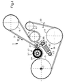
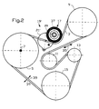
- FIGS. 1 and 2 the same references have been used for designate the same elements.
- the belt 3 passes over a pulley 9 secured in rotation with the axis of an alternator, on a guide roller 11, on a pulley 13 of a hydraulic pump for supplying fluid under steering pressure assisted by the vehicle and on a pulley 15 secured in rotation with the axis of the vehicle engine water pump.
- a roller 17 of a linear tensioner 19 is supported on the external face of the belt 3.
- the tensioner 19 is of the linear type comprising a body 21 provided at a first end with a first eye 23 articulated on an axis fixed to the engine block (not shown), and to a second end of the body 21 opposite the first end of an eye 25 fixed to a first end of lever 27 in L.
- the second end of lever 27 carries the roller 17 swiveling around an axis 29.
- the lever 27 is rotatably mounted on the engine block around an axis 31 located at the intersection of the branches of the L.
- Body 21 of tensioner 19 includes elastic means, for example a coil spring 33, ensuring the application with preload of the roller 17 on the belt 3.
- the prestress exerted on the belt 3 is for example between 20 and 800 N, preferably between 70 and 600 N, advantageously between 80 and 500 N.
- the body 21 of the tensioner 19 further comprises a coaxial hydraulic circuit ensuring vibration absorption longitudinal of the belt, illustrated by arrow 35.
- An example of such hydraulic system is described in the International Application PCT / FR93 / 00245.
- FIG. 2 we can see a device for transmitting power similar to that of FIG. 1 whose linear tensioner 19 has been replaced by a rotary tensioner 19 'comprising elastic means, in particular a spring (not shown) exerting on the roller 17 a couple of return to the belt 3 so as to ensure the application of the roller 17 on the belt 3 with preload.
- the roller 19 ' has a body 21' substantially cylindrical eccentric with respect to the axis of rotation 29 of the roller 17.
- the rollers 17 of the tensioners 19, 19 'according to the present invention may include a plain bearing, in particular ceramic, PTFE or metallic or, advantageously, comprise a bearing, in particular a ball or roller bearing.
- the rollers 17 of the tensioners 19, 19 'according to the present invention have a radially outer bandage or covering 37 in one vibration absorbing material.
- the coating 37 makes it possible to absorb the transverse vibrations 39 of the belt 3.
- vibration absorbing material material which has a tangent ⁇ (values obtained for stresses at 2% in compression, at 100 ° C, at 25 Hz and with a preload of 5%), by example between 0.05 and 0.65, preferably between 0.07 and 0.50, and by example equal to 0.095.
- the material of the treads of the covering 37 is advantageously chosen from chloroprene, EPDM type rubbers, nitrile-butadiene rubbers (HNBR), EPR, ACSM, IIR, materials thermoplastics or thermosets or mixtures thereof.
- the material used has good resistance at high temperatures.
- the outer face of the tread 37 or of the covering 37 can be covered with a fabric, a nonwoven or the like.
- the tread material 37 or covering material 37 a for example a hardness between 30 Shore A and 95 Shore A, preferably between 40 Shore A and 70 Shore A, preferably between 55 Shore A and 65 Shore A.
- the roller 17 can, without departing from the scope of this invention, include lateral flanges, for example metallic.
- the covering or the covering strip 37 of absorbent material vibration is, for example, housed at the bottom of a groove of trapezoidal section defined by the internal walls of the flanges and a cylindrical bottom coaxial at housing of the roller axis.
- the coating of the tread 37 also extends over the internal faces of the flaccid.
- the present invention is particularly applicable to industry mechanical.
- the present invention applies mainly to industry automobile.
Landscapes
- Engineering & Computer Science (AREA)
- General Engineering & Computer Science (AREA)
- Mechanical Engineering (AREA)
- Chemical & Material Sciences (AREA)
- Combustion & Propulsion (AREA)
- Devices For Conveying Motion By Means Of Endless Flexible Members (AREA)
Abstract
Description
- la figure 1 est une vue de profil d'un dispositif mécanique de transmission de puissance comportant un tendeur linéaire selon la présente invention ;
- la figure 2 est une vue de profil d'un dispositif mécanique de transmission de puissance comportant un tendeur rotatif selon la présente invention.
Claims (10)
- Tendeur de courroie comportant des moyens (17) d'appui sur la courroie (3) et des moyens de rappel élastiques (33) assurant l'application avec précontrainte des moyens d'appui (17) sur la courroie, caractérisé en ce que les moyens (17) d'appui sur la courroie (3) comportent en outre un revêtement en matériau absorbant les vibrations.
- Tendeur selon la revendication 1, caractérisé en ce que les moyens d'appui sur la courroie (3) comportent un galet (17) et en ce que le revêtement (37) en matériau absorbant les vibrations est une bande de roulement radialement externe du galet (17) ayant une épaisseur comprise entre 1 et 10 mm.
- Tendeur selon la revendication 1 ou 2, caractérisé en ce que le matériau absorbant les vibrations est un élastomère.
- Tendeur selon l'une quelconque des revendications précédentes, caractérisé en ce que le revêtement en matériau absorbant les vibrations (33) a une dureté comprise entre 30 Shore A et 95 Shore A, de préférence comprise entre 40 Shore A et 70 Shore A.
- Tendeur selon l'une quelconque des revendications précédentes, caractérisé en ce que ledit tendeur est un tendeur linéaire.
- Tendeur selon la revendication 5, caractérisé en ce qu'il comporte un ressort à boudin (33) assurant l'application avec précontrainte des moyens d'application (17) sur la courroie (3) et un circuit hydraulique d'amortissement de la variation de longueur du corps (21) du tendeur.
- Tendeur selon l'une quelconque des revendications 1 à 4, caractérisé en ce que ledit tendeur est un tendeur rotatif.
- Dispositif mécanique de transmission de puissance comportant au moins une poulie menante (5) et une poulie menée (9, 13, 15), une courroie (3) passant par la poulie menante et la ou les poulie(s) menée(s), caractérisé en ce qu'il comporte un tendeur selon l'une quelconque des revendications précédentes dont les moyens (17) d'appui sont appliqués avec précontrainte sur la courroie (3).
- Dispositif selon la revendication 8, caractérisé en ce que ledit dispositif est un dispositif de transmission d'accessoire d'un moteur thermique d'un véhicule automobile comportant une poulie (5) solidarisée en rotation avec l'axe (7) d'un vilebrequin et une poulie (9) solidarisée en rotation avec l'axe d'un alternateur.
- Moteur thermique, caractérisé en ce qu'il comporte un tendeur selon l'une quelconque des revendications 1 à 7 et/ou un dispositif de transmission selon la revendication 8 ou 9.
Applications Claiming Priority (2)
| Application Number | Priority Date | Filing Date | Title |
|---|---|---|---|
| FR9613047 | 1996-10-25 | ||
| FR9613047A FR2755201B1 (fr) | 1996-10-25 | 1996-10-25 | Tendeur pour dispositif mecanique de transmission de puissance, dispositif comportant un tel tendeur et moteur thermique pour vehicule automobile comportant un tel dispositif |
Publications (2)
| Publication Number | Publication Date |
|---|---|
| EP0838608A1 true EP0838608A1 (fr) | 1998-04-29 |
| EP0838608B1 EP0838608B1 (fr) | 2002-07-17 |
Family
ID=9497036
Family Applications (1)
| Application Number | Title | Priority Date | Filing Date |
|---|---|---|---|
| EP97401856A Expired - Lifetime EP0838608B1 (fr) | 1996-10-25 | 1997-08-01 | Tendeur de courroie, dispositif de transmission de puissance comportant un tel tendeur et moteur thermique pour véhicule automobile comportant un tel dispositif |
Country Status (6)
| Country | Link |
|---|---|
| US (1) | US6162141A (fr) |
| EP (1) | EP0838608B1 (fr) |
| JP (1) | JPH10132041A (fr) |
| DE (2) | DE838608T1 (fr) |
| ES (1) | ES2115575T3 (fr) |
| FR (1) | FR2755201B1 (fr) |
Cited By (1)
| Publication number | Priority date | Publication date | Assignee | Title |
|---|---|---|---|---|
| CN102022496A (zh) * | 2009-09-23 | 2011-04-20 | 通用汽车环球科技运作公司 | 附件驱动张紧装置组件 |
Families Citing this family (31)
| Publication number | Priority date | Publication date | Assignee | Title |
|---|---|---|---|---|
| US6540629B2 (en) | 2000-03-29 | 2003-04-01 | The Gates Corporation | Flexible idler |
| US20050155727A1 (en) * | 2004-01-20 | 2005-07-21 | Chin-Lung Lin | Drive device for a sunshade curtain |
| DE102004028484A1 (de) * | 2004-06-11 | 2005-12-29 | Ina-Schaeffler Kg | Reibradantrieb |
| DE102004058770A1 (de) * | 2004-12-07 | 2006-06-08 | Schaeffler Kg | Spannvorrichtung für einen Zugmitteltrieb |
| DE102006031516A1 (de) * | 2006-07-07 | 2008-01-10 | Schaeffler Kg | Kettentrieb mit einem Kettenspanner |
| US8348019B2 (en) * | 2007-06-20 | 2013-01-08 | Inventio Ag | Elevator element for driving or reversing an elevator suspension means in an elevator system |
| KR101241209B1 (ko) * | 2011-01-06 | 2013-03-13 | 현대자동차주식회사 | 하이브리드 차량의 벨트 시스템 |
| KR101219879B1 (ko) | 2011-07-04 | 2013-01-09 | 기아자동차주식회사 | 벨트구동 스타트 시스템 |
| JP5780070B2 (ja) * | 2011-09-06 | 2015-09-16 | トヨタ自動車株式会社 | エンジンのベルト保護装置 |
| US8899408B2 (en) * | 2012-08-03 | 2014-12-02 | Applied Materials, Inc. | Temperature actuated tensioning mechanism |
| BE1023230B1 (nl) * | 2015-08-24 | 2017-01-05 | Cnh Industrial Belgium Nv | Spanrolgeheel voor een riemaandrijving |
| US11014634B2 (en) | 2016-09-09 | 2021-05-25 | Richard L. Hartman | Hydraulic power sources for watercraft and methods for providing hydraulic power aboard a watercraft |
| US10864971B2 (en) | 2016-09-09 | 2020-12-15 | Richard L. Hartman | Wakeboat hydraulic manifold assemblies and methods |
| US10611440B2 (en) | 2016-09-09 | 2020-04-07 | Richard L. Hartman | Boat propulsion assemblies and methods |
| US10611439B2 (en) * | 2016-09-09 | 2020-04-07 | Richard L. Hartman | Wakeboat engine hydraulic pump mounting apparatus and methods |
| US11505289B2 (en) | 2016-09-09 | 2022-11-22 | Richard L. Hartman | Wakeboat bilge measurement assemblies and methods |
| US12600441B2 (en) | 2016-09-09 | 2026-04-14 | Richard L. Hartman | Thruster conduit assemblies |
| US11254395B2 (en) | 2016-09-09 | 2022-02-22 | Richard L. Hartman | Aquatic invasive species control apparatuses and methods for watercraft |
| US11014635B2 (en) | 2016-09-09 | 2021-05-25 | Richard L. Hartman | Power source assemblies and methods for distributing power aboard a watercraft |
| US10829186B2 (en) | 2016-09-09 | 2020-11-10 | Richard L. Hartman | Wakeboat ballast measurement assemblies and methods |
| CA2978824C (fr) | 2016-09-09 | 2021-09-07 | Richard L. Hartman | Appareil de lestage alimente de moteur de planche de wakeboard |
| CN106704141B (zh) * | 2017-01-11 | 2018-06-01 | 厦门金龙联合汽车工业有限公司 | 客车空调压缩机总成隔振与皮带稳定运行的机构 |
| WO2019004131A1 (fr) * | 2017-06-29 | 2019-01-03 | 株式会社クボタ | Dispositif de réglage de tension de courroie et machine de chantier |
| JP6885240B2 (ja) * | 2017-07-13 | 2021-06-09 | スズキ株式会社 | 車両用内燃機関 |
| GB201721786D0 (en) * | 2017-12-22 | 2018-02-07 | Agco Corp | Easy adjust tensioner assembly |
| CN111412263A (zh) * | 2020-04-26 | 2020-07-14 | 江苏沃得农业机械股份有限公司 | 一种由液力传动器输入皮带轮输出动力的割台传动方案 |
| EP4217624A4 (fr) * | 2020-09-22 | 2024-07-24 | 1783590 Ontario Inc. d/b/a Inmotive Inc. | Transmission |
| WO2022115448A1 (fr) * | 2020-11-24 | 2022-06-02 | Milwaukee Electric Tool Corporation | Compacteur à plaque |
| EP4071383B1 (fr) * | 2021-04-09 | 2025-08-27 | Sandvik Ltd | Appareil de tension de courroie de broyeur |
| WO2023172324A1 (fr) * | 2022-03-07 | 2023-09-14 | Husqvarna Ab | Système de réglage de tension de courroie |
| CN220667658U (zh) * | 2022-08-23 | 2024-03-26 | 安瑞安纳能源股份公司 | 热废气能量回收系统 |
Citations (5)
| Publication number | Priority date | Publication date | Assignee | Title |
|---|---|---|---|---|
| GB1394153A (en) * | 1972-02-01 | 1975-05-14 | Pirelli | Toothed belt transmission between toothed pulleys |
| DE2819333A1 (de) * | 1978-05-03 | 1979-11-08 | Audi Nsu Auto Union Ag | Riementrieb fuer eine brennkraftmaschine, insbesondere zahnriementrieb fuer den antrieb einer nockenwelle |
| EP0193802A1 (fr) * | 1985-02-21 | 1986-09-10 | Feldmühle Aktiengesellschaft | Tendeur ou guide-chaîne pour transmission à chaîne |
| EP0541387A1 (fr) * | 1991-11-07 | 1993-05-12 | Tsubakimoto Chain Co. | Dispositif tendeur à ressort externe |
| US5271742A (en) * | 1992-06-30 | 1993-12-21 | Texas Instruments Incorporated | Belt tensioning system and improved belt tensioner |
Family Cites Families (17)
| Publication number | Priority date | Publication date | Assignee | Title |
|---|---|---|---|---|
| US2590182A (en) * | 1950-07-27 | 1952-03-25 | Gates Rubber Co | V belt power transmission system |
| US3216267A (en) * | 1963-02-15 | 1965-11-09 | Dolza John | Rotary motion transmitting mechanism for internal combustion engines and the like |
| US3989314A (en) * | 1975-11-24 | 1976-11-02 | Caterpillar Tractor Co. | Wheel of track assembly of a crawler type vehicle |
| US4324552A (en) * | 1980-03-14 | 1982-04-13 | Deere & Company | Belt drive system with clutch |
| US4557710A (en) * | 1984-02-27 | 1985-12-10 | Greider C Austin | Clutch controlled drive unit |
| US4589861A (en) * | 1984-05-22 | 1986-05-20 | Itek Graphix Corp. | Simple recording head drive having virtually zero backlash or slippage |
| US4878411A (en) * | 1984-12-19 | 1989-11-07 | Laskowski Enterprises, Inc. | Band saw wheel |
| CA1258594A (fr) * | 1985-03-19 | 1989-08-22 | Itsuo Iwai | Mecanisme tendeur pour dispositif d'entrainement a courroie sur moteur a combustion interne |
| US4718544A (en) * | 1985-05-03 | 1988-01-12 | Herren Harold L | Flexible lagging strips for drum pulleys |
| US4822321A (en) * | 1988-07-18 | 1989-04-18 | General Motors Corporation | Combination water pump and belt tensioner |
| DE4120844C1 (fr) * | 1991-06-25 | 1992-11-12 | Audi Ag, 8070 Ingolstadt, De | |
| DE4133777C2 (de) * | 1991-10-11 | 1994-03-17 | Ford Werke Ag | Zahnriementrieb mit zumindest einer Spannrolle |
| US5346438A (en) * | 1992-08-18 | 1994-09-13 | R. G. Technical Associates, Inc. | Belt guide pulley |
| FR2706561B1 (fr) * | 1993-06-09 | 1995-09-01 | Hutchinson | Dispositif de tendeur pour courroie. |
| KR960001555A (ko) * | 1994-06-14 | 1996-01-25 | 사사베 쇼고 | 오토텐셔너 |
| JP3107351B2 (ja) * | 1994-12-28 | 2000-11-06 | 光洋精工株式会社 | オートテンショナ |
| US5769747A (en) * | 1996-09-05 | 1998-06-23 | Deere & Company | Belt tensioning mechanism with stop feature |
-
1996
- 1996-10-25 FR FR9613047A patent/FR2755201B1/fr not_active Expired - Fee Related
-
1997
- 1997-08-01 EP EP97401856A patent/EP0838608B1/fr not_active Expired - Lifetime
- 1997-08-01 ES ES97401856T patent/ES2115575T3/es not_active Expired - Lifetime
- 1997-08-01 DE DE0838608T patent/DE838608T1/de active Pending
- 1997-08-01 DE DE69713983T patent/DE69713983T2/de not_active Expired - Fee Related
- 1997-09-22 US US08/935,134 patent/US6162141A/en not_active Expired - Fee Related
- 1997-10-21 JP JP9288703A patent/JPH10132041A/ja active Pending
Patent Citations (5)
| Publication number | Priority date | Publication date | Assignee | Title |
|---|---|---|---|---|
| GB1394153A (en) * | 1972-02-01 | 1975-05-14 | Pirelli | Toothed belt transmission between toothed pulleys |
| DE2819333A1 (de) * | 1978-05-03 | 1979-11-08 | Audi Nsu Auto Union Ag | Riementrieb fuer eine brennkraftmaschine, insbesondere zahnriementrieb fuer den antrieb einer nockenwelle |
| EP0193802A1 (fr) * | 1985-02-21 | 1986-09-10 | Feldmühle Aktiengesellschaft | Tendeur ou guide-chaîne pour transmission à chaîne |
| EP0541387A1 (fr) * | 1991-11-07 | 1993-05-12 | Tsubakimoto Chain Co. | Dispositif tendeur à ressort externe |
| US5271742A (en) * | 1992-06-30 | 1993-12-21 | Texas Instruments Incorporated | Belt tensioning system and improved belt tensioner |
Cited By (2)
| Publication number | Priority date | Publication date | Assignee | Title |
|---|---|---|---|---|
| CN102022496A (zh) * | 2009-09-23 | 2011-04-20 | 通用汽车环球科技运作公司 | 附件驱动张紧装置组件 |
| CN102022496B (zh) * | 2009-09-23 | 2013-10-16 | 通用汽车环球科技运作公司 | 附件驱动张紧装置组件 |
Also Published As
| Publication number | Publication date |
|---|---|
| US6162141A (en) | 2000-12-19 |
| EP0838608B1 (fr) | 2002-07-17 |
| JPH10132041A (ja) | 1998-05-22 |
| DE838608T1 (de) | 1998-09-24 |
| ES2115575T3 (es) | 2002-12-16 |
| DE69713983D1 (de) | 2002-08-22 |
| ES2115575T1 (es) | 1998-07-01 |
| FR2755201B1 (fr) | 1998-12-04 |
| DE69713983T2 (de) | 2003-03-13 |
| FR2755201A1 (fr) | 1998-04-30 |
Similar Documents
| Publication | Publication Date | Title |
|---|---|---|
| EP0838608B1 (fr) | Tendeur de courroie, dispositif de transmission de puissance comportant un tel tendeur et moteur thermique pour véhicule automobile comportant un tel dispositif | |
| EP0375516B1 (fr) | Dispositif de tension par transmission par lien souple à double galet sur bague élastique de torsion | |
| FR2566081A1 (fr) | Tendeur de courroie | |
| FR2705128A1 (fr) | Dispositif tendeur de chaîne pour le réglage et le maintien en continu de la tension correcte de la courroie de distribution d'un véhicule automobile. | |
| FR2817306A1 (fr) | Systeme d'entrainement | |
| WO2007034060A1 (fr) | Poulie de transmission de puissance | |
| FR2992707A1 (fr) | Rouleau de tension et tendeur pour transmission a courroie d'un moteur a combustion interne | |
| FR2497901A1 (fr) | Dispositif de tension de courroie | |
| FR2587078A1 (fr) | Dispositif de tension automatique de courroie, notamment pour courroie de synchronisation d'arbre a cames | |
| FR2712056A1 (fr) | Dispositif pour la mise sous tension d'une commande de distribution. | |
| FR2635569A1 (fr) | Dispositif de serrage automatique pour galet tendeur | |
| FR2688565A1 (fr) | Tendeur pour courroie et systeme de transmission comportant un tel tendeur. | |
| KR101186810B1 (ko) | 블레이드 스프링을 구비한 컴플리언트 체인 가이드 | |
| US8267821B2 (en) | Mechanical tensioner with damping mechanism | |
| EP0373056B1 (fr) | Galet tendeur pour transmission par lien souple | |
| EP0362451A1 (fr) | Dispositif de compensation de dilatation thermique sur galet tendeur de transmission par lien souple ou articulé | |
| FR2857897A1 (fr) | Outil de travail guide manuellement | |
| FR3027645A1 (fr) | Dispositif de poulie pour chaine ou courroie et vehicule automobile equipe d'un tel dispositif | |
| FR2772857A1 (fr) | Tendeur, moteur comportant un tel tendeur et procede de montage d'un tel tendeur | |
| EP0300858A1 (fr) | Dispositif de tendeur rotatif pour courroie de transmission de puissance | |
| EP0055162B1 (fr) | Dispositif de tension et de guidage pour chaîne ou courroie sans fin | |
| EP2860424A1 (fr) | Butée pour galet tendeur d'une courroie | |
| EP0868617B1 (fr) | Dispositif mecanique de transmission de puissance et moteur comportant un tel dispositif | |
| EP0628750B1 (fr) | Dispositif de tendeur pour courroie | |
| EP1464872B1 (fr) | Tendeur de courroie d'entraînement |
Legal Events
| Date | Code | Title | Description |
|---|---|---|---|
| PUAI | Public reference made under article 153(3) epc to a published international application that has entered the european phase |
Free format text: ORIGINAL CODE: 0009012 |
|
| AK | Designated contracting states |
Kind code of ref document: A1 Designated state(s): BE DE ES GB IT LU NL SE |
|
| AX | Request for extension of the european patent |
Free format text: AL;LT;LV;RO;SI |
|
| 17P | Request for examination filed |
Effective date: 19980427 |
|
| REG | Reference to a national code |
Ref country code: ES Ref legal event code: BA2A Ref document number: 2115575 Country of ref document: ES Kind code of ref document: T1 |
|
| GBC | Gb: translation of claims filed (gb section 78(7)/1977) | ||
| TCNL | Nl: translation of patent claims filed | ||
| RAP1 | Party data changed (applicant data changed or rights of an application transferred) |
Owner name: HUTCHINSON |
|
| DET | De: translation of patent claims | ||
| AKX | Designation fees paid |
Free format text: BE DE ES GB IT LU NL SE |
|
| RBV | Designated contracting states (corrected) |
Designated state(s): BE DE ES GB IT LU NL SE |
|
| 17Q | First examination report despatched |
Effective date: 19991004 |
|
| GRAG | Despatch of communication of intention to grant |
Free format text: ORIGINAL CODE: EPIDOS AGRA |
|
| GRAG | Despatch of communication of intention to grant |
Free format text: ORIGINAL CODE: EPIDOS AGRA |
|
| GRAH | Despatch of communication of intention to grant a patent |
Free format text: ORIGINAL CODE: EPIDOS IGRA |
|
| GRAH | Despatch of communication of intention to grant a patent |
Free format text: ORIGINAL CODE: EPIDOS IGRA |
|
| GRAA | (expected) grant |
Free format text: ORIGINAL CODE: 0009210 |
|
| AK | Designated contracting states |
Kind code of ref document: B1 Designated state(s): BE DE ES GB IT LU NL SE |
|
| REG | Reference to a national code |
Ref country code: GB Ref legal event code: FG4D Free format text: NOT ENGLISH |
|
| GBT | Gb: translation of ep patent filed (gb section 77(6)(a)/1977) |
Effective date: 20020717 |
|
| REF | Corresponds to: |
Ref document number: 69713983 Country of ref document: DE Date of ref document: 20020822 |
|
| REG | Reference to a national code |
Ref country code: ES Ref legal event code: FG2A Ref document number: 2115575 Country of ref document: ES Kind code of ref document: T3 |
|
| PLBE | No opposition filed within time limit |
Free format text: ORIGINAL CODE: 0009261 |
|
| STAA | Information on the status of an ep patent application or granted ep patent |
Free format text: STATUS: NO OPPOSITION FILED WITHIN TIME LIMIT |
|
| 26N | No opposition filed |
Effective date: 20030422 |
|
| PGFP | Annual fee paid to national office [announced via postgrant information from national office to epo] |
Ref country code: GB Payment date: 20040804 Year of fee payment: 8 |
|
| PGFP | Annual fee paid to national office [announced via postgrant information from national office to epo] |
Ref country code: LU Payment date: 20040806 Year of fee payment: 8 |
|
| PGFP | Annual fee paid to national office [announced via postgrant information from national office to epo] |
Ref country code: SE Payment date: 20040813 Year of fee payment: 8 |
|
| PGFP | Annual fee paid to national office [announced via postgrant information from national office to epo] |
Ref country code: NL Payment date: 20040818 Year of fee payment: 8 |
|
| PGFP | Annual fee paid to national office [announced via postgrant information from national office to epo] |
Ref country code: BE Payment date: 20040902 Year of fee payment: 8 |
|
| PGFP | Annual fee paid to national office [announced via postgrant information from national office to epo] |
Ref country code: ES Payment date: 20050614 Year of fee payment: 9 |
|
| PG25 | Lapsed in a contracting state [announced via postgrant information from national office to epo] |
Ref country code: LU Free format text: LAPSE BECAUSE OF NON-PAYMENT OF DUE FEES Effective date: 20050801 Ref country code: GB Free format text: LAPSE BECAUSE OF NON-PAYMENT OF DUE FEES Effective date: 20050801 |
|
| PG25 | Lapsed in a contracting state [announced via postgrant information from national office to epo] |
Ref country code: SE Free format text: LAPSE BECAUSE OF NON-PAYMENT OF DUE FEES Effective date: 20050802 |
|
| PGFP | Annual fee paid to national office [announced via postgrant information from national office to epo] |
Ref country code: DE Payment date: 20050812 Year of fee payment: 9 |
|
| PG25 | Lapsed in a contracting state [announced via postgrant information from national office to epo] |
Ref country code: BE Free format text: LAPSE BECAUSE OF NON-PAYMENT OF DUE FEES Effective date: 20050831 |
|
| PG25 | Lapsed in a contracting state [announced via postgrant information from national office to epo] |
Ref country code: NL Free format text: LAPSE BECAUSE OF NON-PAYMENT OF DUE FEES Effective date: 20060301 |
|
| EUG | Se: european patent has lapsed | ||
| GBPC | Gb: european patent ceased through non-payment of renewal fee |
Effective date: 20050801 |
|
| NLV4 | Nl: lapsed or anulled due to non-payment of the annual fee |
Effective date: 20060301 |
|
| PGFP | Annual fee paid to national office [announced via postgrant information from national office to epo] |
Ref country code: IT Payment date: 20060831 Year of fee payment: 10 |
|
| PG25 | Lapsed in a contracting state [announced via postgrant information from national office to epo] |
Ref country code: DE Free format text: LAPSE BECAUSE OF NON-PAYMENT OF DUE FEES Effective date: 20070301 |
|
| REG | Reference to a national code |
Ref country code: ES Ref legal event code: FD2A Effective date: 20060802 |
|
| BERE | Be: lapsed |
Owner name: *HUTCHINSON Effective date: 20050831 |
|
| PG25 | Lapsed in a contracting state [announced via postgrant information from national office to epo] |
Ref country code: ES Free format text: LAPSE BECAUSE OF NON-PAYMENT OF DUE FEES Effective date: 20060802 |
|
| PG25 | Lapsed in a contracting state [announced via postgrant information from national office to epo] |
Ref country code: IT Free format text: LAPSE BECAUSE OF NON-PAYMENT OF DUE FEES Effective date: 20070801 |