EP0838609A2 - Variateur continu de vitesse à poulies coniques - Google Patents
Variateur continu de vitesse à poulies coniques Download PDFInfo
- Publication number
- EP0838609A2 EP0838609A2 EP97115800A EP97115800A EP0838609A2 EP 0838609 A2 EP0838609 A2 EP 0838609A2 EP 97115800 A EP97115800 A EP 97115800A EP 97115800 A EP97115800 A EP 97115800A EP 0838609 A2 EP0838609 A2 EP 0838609A2
- Authority
- EP
- European Patent Office
- Prior art keywords
- conical
- transmission
- shaft
- belt
- wrapping means
- Prior art date
- Legal status (The legal status is an assumption and is not a legal conclusion. Google has not performed a legal analysis and makes no representation as to the accuracy of the status listed.)
- Granted
Links
Images





Classifications
-
- B—PERFORMING OPERATIONS; TRANSPORTING
- B60—VEHICLES IN GENERAL
- B60K—ARRANGEMENT OR MOUNTING OF PROPULSION UNITS OR OF TRANSMISSIONS IN VEHICLES; ARRANGEMENT OR MOUNTING OF PLURAL DIVERSE PRIME-MOVERS IN VEHICLES; AUXILIARY DRIVES FOR VEHICLES; INSTRUMENTATION OR DASHBOARDS FOR VEHICLES; ARRANGEMENTS IN CONNECTION WITH COOLING, AIR INTAKE, GAS EXHAUST OR FUEL SUPPLY OF PROPULSION UNITS IN VEHICLES
- B60K17/00—Arrangement or mounting of transmissions in vehicles
- B60K17/04—Arrangement or mounting of transmissions in vehicles characterised by arrangement, location or kind of gearing
-
- B—PERFORMING OPERATIONS; TRANSPORTING
- B60—VEHICLES IN GENERAL
- B60K—ARRANGEMENT OR MOUNTING OF PROPULSION UNITS OR OF TRANSMISSIONS IN VEHICLES; ARRANGEMENT OR MOUNTING OF PLURAL DIVERSE PRIME-MOVERS IN VEHICLES; AUXILIARY DRIVES FOR VEHICLES; INSTRUMENTATION OR DASHBOARDS FOR VEHICLES; ARRANGEMENTS IN CONNECTION WITH COOLING, AIR INTAKE, GAS EXHAUST OR FUEL SUPPLY OF PROPULSION UNITS IN VEHICLES
- B60K17/00—Arrangement or mounting of transmissions in vehicles
- B60K17/02—Arrangement or mounting of transmissions in vehicles characterised by arrangement, location, or kind of clutch
-
- F—MECHANICAL ENGINEERING; LIGHTING; HEATING; WEAPONS; BLASTING
- F16—ENGINEERING ELEMENTS AND UNITS; GENERAL MEASURES FOR PRODUCING AND MAINTAINING EFFECTIVE FUNCTIONING OF MACHINES OR INSTALLATIONS; THERMAL INSULATION IN GENERAL
- F16H—GEARING
- F16H15/00—Gearings for conveying rotary motion with variable gear ratio, or for reversing rotary motion, by friction between rotary members
- F16H15/02—Gearings for conveying rotary motion with variable gear ratio, or for reversing rotary motion, by friction between rotary members without members having orbital motion
- F16H15/04—Gearings providing a continuous range of gear ratios
- F16H15/42—Gearings providing a continuous range of gear ratios in which two members co-operate by means of rings or by means of parts of endless flexible members pressed between the first mentioned members
-
- F—MECHANICAL ENGINEERING; LIGHTING; HEATING; WEAPONS; BLASTING
- F16—ENGINEERING ELEMENTS AND UNITS; GENERAL MEASURES FOR PRODUCING AND MAINTAINING EFFECTIVE FUNCTIONING OF MACHINES OR INSTALLATIONS; THERMAL INSULATION IN GENERAL
- F16H—GEARING
- F16H15/00—Gearings for conveying rotary motion with variable gear ratio, or for reversing rotary motion, by friction between rotary members
- F16H15/48—Gearings for conveying rotary motion with variable gear ratio, or for reversing rotary motion, by friction between rotary members with members having orbital motion
- F16H15/50—Gearings providing a continuous range of gear ratios
- F16H15/54—Gearings providing a continuous range of gear ratios in which two members co-operate by means of rings or by means of parts of endless flexible members pressed between the first-mentioned members
-
- F—MECHANICAL ENGINEERING; LIGHTING; HEATING; WEAPONS; BLASTING
- F16—ENGINEERING ELEMENTS AND UNITS; GENERAL MEASURES FOR PRODUCING AND MAINTAINING EFFECTIVE FUNCTIONING OF MACHINES OR INSTALLATIONS; THERMAL INSULATION IN GENERAL
- F16H—GEARING
- F16H15/00—Gearings for conveying rotary motion with variable gear ratio, or for reversing rotary motion, by friction between rotary members
- F16H15/02—Gearings for conveying rotary motion with variable gear ratio, or for reversing rotary motion, by friction between rotary members without members having orbital motion
- F16H15/04—Gearings providing a continuous range of gear ratios
- F16H15/06—Gearings providing a continuous range of gear ratios in which a member A of uniform effective diameter mounted on a shaft may co-operate with different parts of a member B
- F16H15/16—Gearings providing a continuous range of gear ratios in which a member A of uniform effective diameter mounted on a shaft may co-operate with different parts of a member B in which the member B has a conical friction surface
- F16H15/24—Gearings providing a continuous range of gear ratios in which a member A of uniform effective diameter mounted on a shaft may co-operate with different parts of a member B in which the member B has a conical friction surface internally
Definitions
- the invention relates to a continuously adjustable belt transmission according to the preamble of claim 1.
- Such a belt transmission is known for example from DE-OS 44 43 020.
- conical pulley belt drives are from the paperback for the mechanical engineering, Dubbel, 14th edition, page 447, picture 4 known other gear types, with which the gear ratio can be changed continuously.
- CVT transmissions conical pulley belt transmissions
- the object of the invention is therefore a continuously variable belt transmission with good transmission efficiency, especially with long gear ratios to introduce, and to specify an associated drive arrangement for a vehicle.
- the transmission should be clear in comparison to the previously known automatic transmissions fewer components get by, so that this is inexpensive and space-saving can be produced.
- the continuously variable belt transmission according to the invention is essentially made up of two sets of conical disks arranged concentrically to each other, which are non-positively connected to each other via a belt.
- a further special feature of this belt transmission is both sets of conical pulleys either only on the transmission input shaft or only on the transmission output shaft, while the free shaft is attached by means of the outer conical disks External gears via gears or flexible belt means such as wedge or Timing belt can be driven.
- the inner and outer conical disks can be preferred be provided that one of the conical disks of the outer pair of conical disks is rotatable and rotatable axially immovable on the drive shaft and the other outer conical disk arranged in the region of a section of the drive shaft with a reduced diameter is.
- outer conical disc is also axially displaceable.
- this outer conical washer on an axial extension also axially slidably arranged on the reduced diameter drive shaft section inner conical disc is rotatably mounted. It is particularly advantageous to see if the axially displaceable inner conical disc is reduced to the diameter Drive shaft section is mounted and the outer conical washers on the drive shaft or the coaxial tapered disk section are roller-supported and axially supported.
- the Wrapping means can preferably be provided that the axial bearing of the axial movable outer conical disc against one on the axial extension of the axial Movable inner conical disc arranged ring, which in turn acts on its of the thrust bearing side by means of a reset arrangement against the thrust bearing and thus acts against the axially displaceable outer conical disk.
- This Reset assembly can act as a between the ring and an end collar the extension of the axially displaceable inner conical spring element or a piston-cylinder arrangement operated by pressure medium.
- the axially displaceable inner conical disk is adjusted by the adjustment of the transmission medium.
- a pressure medium operated actuator can be provided, the contact pressure depending on the translation and / or the Input torque is regulated.
- the wrapping means can be a coated metal component be carried out in which a metallic core is enclosed by a friction material.
- a friction material In other variants can be provided that also or only the Tapered disk raceways are provided with such a friction material.
- the wrapping means has an outer contour that is suitable for that of the inner Conical disc set with its radially outward opening conical discs Take up torque and on the conical disks that close radially outwards of the outer conical disk set.
- the axial end faces of the belt means are substantially V-shaped are.
- the belt means on its radial Outer circumference is a U-shaped, a V-shaped, a semicircular, an elliptical depression or has a cross-sectional geometry having a rectangular incision, which for Inclusion of an adjusting device exerting an adjusting force on the belt suitable is.
- the wrapping means has an approximately double-T cross-sectional geometry having.
- the radially inner T-leg is in the area of the arranged inner and outer conical surfaces of the two conical disk pairs and with the radially outer T-leg connected via a ring section that extends radially outside the outer conical washers is sufficient.
- the radially outer T-leg can have a Recess to be provided for receiving pressure elements.
- the wrapping means have a cross-sectional geometry with an outer contour with at least four radii r 1 to r 4 , the radii r 1 , r 2 each being larger than the radii r 3 , r 4 .
- the surface pressure between the wrapping means and the conical disk surfaces can be set to values which are just admissible in relation to the materials of the friction pairing.
- the areas of the belt means with the smaller outer contour radii r 1 , r 2 form the friction surfaces for the inner cone pulleys and the areas with the outer contour radii r 3 and r 4 form the friction surfaces for the outer cone pulleys of the belt transmission.
- the outer contour of the belt means has further outer contour radii r 5 , r 6 , which are formed between the outer contour radii r 1 , r 3 and r 2 , r 4 .
- the outer contour radii r 5 , r 6 are preferably larger than the radii r 3 and r 4 .
- an adjustment device is proposed the at least one pressing element engaging in a looping means recess includes.
- This adjustment device is mounted on the gear housing and essentially is arranged radially to the longitudinal axis of the shaft.
- the adjusting device can be an actuating rod Piston-cylinder arrangement can be formed, which has at least one at its free end rotatably mounted pressure roller or a slide shoe.
- the actuator of the adjustment direction is formed as a circular arc-shaped sheet metal component, on the looping means facing side at least one pressing element, but preferably rotatable stored pressure rollers are attached. These roles engage in the recess of the Wrapping means and thus exercise the necessary adjusting force to set the desired one Gear ratio.
- This circular arc-shaped actuator is also included one end preferably rotatably mounted on the gear housing, while on the other free end of a housing-fixed actuating device is coupled.
- the adjusting device is designed as an adjusting lever, which is rotatably mounted with a free end on the gear housing and on it to the Tapered disk-facing side at least one pressure roller rotatably or one Wears slide shoe. On the other side of the adjusting lever, which points away from the conical disks it is connected to a preferably pressure-medium actuating device.
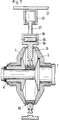
- FIG. 1 comprises a belt transmission according to the invention two coaxially arranged to each other Conical disc sets, both arranged on the transmission input shaft 7, 8 are.
- the inner conical disk set consists of a fixedly connected to the input shaft 7, 8 Conical disk 2, and a section 8 with a reduced diameter the transmission input shaft is non-rotatably but axially displaceable conical disc 3.
- the conical pulleys 2, 3 of this inner conical pulley set have radial externally opening conical surfaces 9, 10.
- the inner cone pulley set is made up of an outer cone pulley set with the cone pulleys 4, 5 includes the space between the conical disks radially outwards 4, 5 have tapered conical surfaces 11, 12.
- a conical disk 5 is on the transmission input shaft 7 and the other conical disk 4 on an axial extension 22 of the inner conical disk 3 mounted on roller bearings 13, 14 and thrust bearings 15, 16. While the thrust bearing 15 in this embodiment of the invention on a shaft collar 19 of the transmission input shaft section 7 supports and thus an axial mobility of the outer conical disk 5th does not allow, the outer conical disk 4 is axially against one on the conical disk extension 22 arranged ring 21 supported, which in turn on a spring element 23 on a Extension collar 24 of the axially movable inner conical disk 3 is supported. The arrangement of this spring element 23 essentially serves to compensate for axial Manufacturing tolerances.
- Reset means 27 are provided, which section 8 of the transmission input shaft is reduced in diameter comprises and between a shaft collar 26 of the transmission input shaft and supports the end face 24 of the extension 22 of the conical disk 3.
- Actuators 90 such as piston-cylinder arrangements for generating the contact pressure of the conical disks are used in the transmission means ( Figure 6).
- a Wrapping means 6 arranged, which consists of a rigid ring.
- This belt 6 has a cross-sectional geometry on its axial end faces 32, 33 which is essentially V-shaped in character.
- the V-legs are in such a way Angle to each other that this in all gear ratios of the gearbox on the conical surfaces 9, 10; 11, 12 of the inner and outer conical pulleys 2, 3, 4, 5 for torque transmission issue.
- the belt means 6 is designed that a depression 73 is formed on the radial outer circumference thereof, in the at least a pressing means 34 of an adjusting device 35 engages. With the help of the adjustment direction the wrapping means can be exerted on the wrapping means in different gear ratios between the inner and outer conical pulleys bring.
- the adjustment device for the belt transmission from an actuator 35 with an arcuate section 39, in which two arranged on axes of rotation 63, 74 rotatably mounted pressing means for the belt are, which are designed here as pressure rollers 41, 42. These pressure rollers grip in the depression 73 of the belt 6 and can be guided laterally to the Adjustment of the transmission ratio necessary force on the belt 6 exercise.
- the actuator 35 which is constructed, for example, as a sheet metal component, is included the pivot point 61 fixed to the gear housing but pivoted.
- the second articulation point 62 can be connected to an actuating device, not shown here.
- the belt is there 6 in the area of the drive axle 8 and in the outer periphery of the outer Conical washers 4, 5.
- This transmission ratio is also in the cross-sectional representation shown in Figure 4.
- FIG. 5 shows how the articulation points 61 and 62 on the two free ends 43, 44 of the actuator 35 on the gear housing 37 and on a piston rod 38 of a gear housing fixed pressure-actuated piston-cylinder arrangement 25 can be fastened.
- electrically driven ones can also be used Stepper motor systems are used.
- FIG. 6 Another adjustment device for setting the gear ratio of the transmission is shown in Figure 6.
- a piston-cylinder arrangement attached to the transmission housing 37 also acts here 25 to the transmission means 6.
- this is not an arcuate actuator, but essentially one rod-shaped actuating lever 45 is provided, which as an extended piston rod at its Cylinder of the piston-cylinder arrangement 25 has a pioneering end on an axis of rotation 83 carries two rollers 34 engaging in the recess 73 of the looping element 6.
- the wrapping element 6 can a further ring gear 64 are actuated that this has a T-cross section and through at least one opening 105 through the non-rotatably connected outer conical washers 4, 5 is passed. It is closer to the drive shaft 7, 8 pointing legs in the manner already described with roles that on the Transmission means 86 act.
- On the outer circumference of the ring gear 64 one or several pressing elements 65 for adjusting the transmission ratio of the transmission exert a contact pressure.
- the pressure roller 65 is the bearing device 66 with the piston rod 67 of the Piston cylinder assembly 25 connected, which in turn is attached to the gear housing 37.
- FIG. 8 A last variant of the adjusting devices for the belt transmission according to the invention is shown in Figure 8.
- This embodiment of the invention is an actuating lever 45, which has one end 46 via a pivot point 68 on the transmission housing 37 is pivotally mounted.
- two pressure rollers 71, 72 are rotatably mounted, to adjust the gear ratio of the transmission to the belt 6 can exert a positioning force. This force is determined by means of a piston-cylinder arrangement 51 applied, the piston rod 50 with the pivot lever 45 pivotally connected is.
- Figures 9 to 14 show different embodiments of the belt 6, 86 in cross-sectional representation.
- a transmission medium can be used, the outer contour of which with the Conical surfaces 9, 10, 11, 12 of the conical disks 2, 3, 4, 5 in axial contact End faces are approximately V-shaped with a broken V-tip.
- the V-legs form to the vertical 95 (or to the drive shaft surface normal) the angles ⁇ and ⁇ , the cone surface angles of the inner and outer conical disks to this Surface normals 95 correspond (FIG. 10).
- the rollers 71, 72 or slide shoes is on the radially outward-facing side of the belt means 6 is rectangular here trained recess 73 is provided.
- the wrapping means comprises a metallic core 75 and an outer skin 30 for example, has a rubber-elastic material.
- the wrapping means according to FIG. 10 also shows the same structure. Here is however, a recess 77 having an elliptical section is provided.
- the looping means according to FIG. 11 shows a semicircular recess 78 and is made entirely of metal, while the transmission means according to FIG provides a flat running surface 79 for the pressing element or elements of the adjusting device.
- this wrapping means 6 is made entirely of an elastic material 85 made, preferably fiber-reinforced, e.g. B. with aramid fibers or carbon fibers, is constructed.
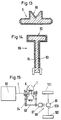
- FIG. 13 shows a belt means in the rubber-metal construction already mentioned, in which the recess 80 has an approximately V-shaped geometry.
- FIG. 14 shows the ring gear 86 already shown in FIG. 7. This has a T cross-sectional area , with the T-leg 82 facing the pressing element one has a flat tread.
- this ring gear is also constructed here as a composite component, at which is a metal core 84 from a layer of fiber reinforced rubber-like material 83 is surrounded.
- FIG Drive motor A drive arrangement for a motor vehicle is shown in FIG Drive motor is called, the shaft 7 with the inner conical pulley set gear 1 according to the invention is connected.
- the outer pair of conical disks is driving an output shaft as already described by means of an engagement toothing and gear wheels 94 58, which has a reversing gear 97 and a starting clutch 89 with a differential gear 99 is connected.
- Axle drive shafts go from this gear 99 in a known manner 100, which are in drive connection with vehicle wheels 101, 102.
- FIGS. 16 and 17 show further different embodiments of the belt means 6 in a cross-sectional illustration.
- the outer contour A has at least four radii r 1 , r 2 and r 3 , r 4 , the former radii r 1 and r 2 each being larger than the radii r 3 and r 4 .
- the areas of the wrapping means 6 with the outer contour radii r 1 , r 2 are the friction surfaces for the inner conical disks 2, 3 and the areas with the outer contour radii r 3 , r 4 are the friction surfaces for form the outer conical pulleys 4, 5 of the belt transmission 1.
- the cross-sectional geometry of the wrapping means 6 has an essentially U-shaped structure, a depression 73 for receiving the described pressing means 34, 36 also being provided on the radially outward-facing side of the wrapping means.
- the outer contour B of the belt means 6 can also have additional radii r 5 and r 6 , which are formed between the outer contour radii r 1 , r 3 and r 2 , r 4 .
- these outer contour radii r 5 , r 6 are larger than the radii r 3 and r 4 , there is a material and thus weight-saving constriction of the belt means 6.
Landscapes
- Engineering & Computer Science (AREA)
- General Engineering & Computer Science (AREA)
- Mechanical Engineering (AREA)
- Chemical & Material Sciences (AREA)
- Combustion & Propulsion (AREA)
- Transportation (AREA)
- Transmissions By Endless Flexible Members (AREA)
- Friction Gearing (AREA)
- Pulleys (AREA)
- Transmission Devices (AREA)
Applications Claiming Priority (4)
| Application Number | Priority Date | Filing Date | Title |
|---|---|---|---|
| DE19643437 | 1996-10-22 | ||
| DE19643437A DE19643437C2 (de) | 1996-10-22 | 1996-10-22 | Stufenlos verstellbares Getriebe |
| DE19649142A DE19649142B4 (de) | 1996-10-22 | 1996-11-27 | Biegesteifes Drehmomentübertragungsmittel für ein stufenloses Umschlingungsgetriebe, nämlich für ein stufenloses verstellbares Getriebe |
| DE19649142 | 1996-11-27 |
Publications (3)
| Publication Number | Publication Date |
|---|---|
| EP0838609A2 true EP0838609A2 (fr) | 1998-04-29 |
| EP0838609A3 EP0838609A3 (fr) | 2000-03-08 |
| EP0838609B1 EP0838609B1 (fr) | 2003-11-26 |
Family
ID=26030555
Family Applications (1)
| Application Number | Title | Priority Date | Filing Date |
|---|---|---|---|
| EP97115800A Expired - Lifetime EP0838609B1 (fr) | 1996-10-22 | 1997-09-11 | Variateur continu de vitesse à poulies coniques |
Country Status (4)
| Country | Link |
|---|---|
| US (1) | US5961417A (fr) |
| EP (1) | EP0838609B1 (fr) |
| JP (1) | JP3914307B2 (fr) |
| DE (3) | DE19643437C2 (fr) |
Cited By (1)
| Publication number | Priority date | Publication date | Assignee | Title |
|---|---|---|---|---|
| WO2007067038A3 (fr) * | 2005-12-05 | 2008-03-13 | Hamapro Holding B V | Transmission a variation continue avec element de transmission en forme de disque fait d’une piece |
Families Citing this family (9)
| Publication number | Priority date | Publication date | Assignee | Title |
|---|---|---|---|---|
| NL1014505C2 (nl) * | 1999-09-15 | 2001-03-16 | Hamapro Holding B V | Continu variabele transmissie. |
| NL1014153C2 (nl) * | 2000-01-24 | 2001-07-25 | Hamapro Holding B V | Torsiesensor. |
| US6306055B1 (en) | 2000-02-22 | 2001-10-23 | The Gates Corporation | Multi-ribbed CVT belt |
| AU2003300500A1 (en) | 2003-01-06 | 2004-07-29 | Ulrich Rohs | Pressing device for tensioning two gearing elements, gearing provided with a pressing device of this type, and method for operating such a friction gearing |
| DE10348718A1 (de) * | 2003-06-17 | 2005-06-30 | Ulrich Dr.-Ing. Rohs | Anpresseinrichtung zum Verspannen zweier Getriebeglieder und Getriebe mit einer derartigen Anpresseinrichtung |
| DE102004028484A1 (de) * | 2004-06-11 | 2005-12-29 | Ina-Schaeffler Kg | Reibradantrieb |
| EP1643167A1 (fr) * | 2004-09-22 | 2006-04-05 | Svein Wieneke | Variateur de vitesse à courroie |
| AT510574B1 (de) * | 2011-01-27 | 2012-05-15 | Avl List Gmbh | Reibradgetriebe |
| DE102017116098B4 (de) * | 2017-07-18 | 2019-05-16 | Viktor Schweizer | Verstellbares Kegelscheibengetriebe |
Family Cites Families (14)
| Publication number | Priority date | Publication date | Assignee | Title |
|---|---|---|---|---|
| US31361A (en) * | 1861-02-05 | Hardening and tempering wire | ||
| US2686432A (en) * | 1949-10-28 | 1954-08-17 | Walter E Gudert | Mechanical infinitely variable speed transmission |
| US2881622A (en) * | 1953-08-18 | 1959-04-14 | Excelermatic | Power transmission device |
| DE1180599B (de) * | 1957-04-29 | 1964-10-29 | Reliance Electric & Eng Co | Reibraederwechselgetriebe |
| DE1200631B (de) * | 1961-09-06 | 1965-09-09 | Hans David Heynau | Stufenlos verstellbares Reibringgetriebe |
| DE1232428B (de) * | 1962-11-29 | 1967-01-12 | Karl Maichen | Reibkegelgetriebe |
| FR1353802A (fr) * | 1963-04-02 | 1964-02-28 | Cosmec Soc N Coll De Granata E | Variateur de vitesse continu, muni d'un volant de commande permettant de faire varier progressivement le rapport de vitesse entre l'arbre primaire et l'arbre secondaire |
| AT256578B (de) * | 1965-07-15 | 1967-08-25 | Karl Maichen | Reibradgetriebe |
| US3633430A (en) * | 1970-01-26 | 1972-01-11 | Arthur P Bentley | Reduction gear transmission |
| FR2174381A5 (fr) * | 1972-03-02 | 1973-10-12 | Peugeot & Renault | |
| USRE31361E (en) | 1979-03-02 | 1983-08-30 | Borg-Warner Corporation | Variable pulley transmission |
| JPS6426049A (en) * | 1987-07-21 | 1989-01-27 | Toyota Motor Corp | Power transmission device of continuously variable transmission |
| US4924730A (en) * | 1987-08-25 | 1990-05-15 | Jaguar Cars Limited | Transmission systems |
| DE4434020B4 (de) * | 1993-10-09 | 2004-04-29 | Volkswagen Ag | Stufenloses Umschlingsungsgetriebe mit einer Sumpfölfördereinrichtung |
-
1996
- 1996-10-22 DE DE19643437A patent/DE19643437C2/de not_active Expired - Fee Related
- 1996-11-27 DE DE19649142A patent/DE19649142B4/de not_active Expired - Fee Related
-
1997
- 1997-09-11 EP EP97115800A patent/EP0838609B1/fr not_active Expired - Lifetime
- 1997-09-11 DE DE59711050T patent/DE59711050D1/de not_active Expired - Lifetime
- 1997-10-16 US US08/951,860 patent/US5961417A/en not_active Expired - Fee Related
- 1997-10-21 JP JP28895397A patent/JP3914307B2/ja not_active Expired - Fee Related
Cited By (1)
| Publication number | Priority date | Publication date | Assignee | Title |
|---|---|---|---|---|
| WO2007067038A3 (fr) * | 2005-12-05 | 2008-03-13 | Hamapro Holding B V | Transmission a variation continue avec element de transmission en forme de disque fait d’une piece |
Also Published As
| Publication number | Publication date |
|---|---|
| JP3914307B2 (ja) | 2007-05-16 |
| DE19643437A1 (de) | 1998-04-23 |
| EP0838609B1 (fr) | 2003-11-26 |
| DE19649142A1 (de) | 1998-07-02 |
| US5961417A (en) | 1999-10-05 |
| DE19643437C2 (de) | 1998-12-24 |
| EP0838609A3 (fr) | 2000-03-08 |
| DE19649142B4 (de) | 2009-06-04 |
| JPH10169744A (ja) | 1998-06-26 |
| DE59711050D1 (de) | 2004-01-08 |
Similar Documents
| Publication | Publication Date | Title |
|---|---|---|
| DE60204713T2 (de) | Ein verbessertes stufenloses getriebe | |
| DE1217165B (de) | Schwenkrollengetriebe | |
| EP0528381A1 (fr) | Moyen d'entraînement pour un véhicule, en particulier pour bicyclette avec un rapport de transmission continuellement variable | |
| DE2734630C2 (de) | Zweisträngiges stufenlos einstellbares Kegelscheibenumschlingungsgetriebe mit gleichmäßiger Lastverteilung | |
| WO2009118218A1 (fr) | Dispositif destiné à réduire le bruit de cliquetis dans des boîtes de vitesses à plusieurs rapports | |
| DE2641698C3 (de) | Umlaufrädergetriebe mit stufenlos willkürlich einstellbarer Übersetzung und mit drehmomentabhängiger Überlagerung der Übersetzungseinstellung | |
| DE10018243A1 (de) | Stufenlos übersetzungsverstellbares Kegelscheibenumschlingungsgetriebe | |
| DE19643437C2 (de) | Stufenlos verstellbares Getriebe | |
| DE4321588C2 (de) | Stufenloses Reibrollengetriebe | |
| DE19743675A1 (de) | Getriebe | |
| DE19734962A1 (de) | Richtungsgeschaltete Kupplung | |
| DE4439993C2 (de) | Stufenloses Getriebe | |
| EP3187751B1 (fr) | Train epicycloïdal continu | |
| DE10222520A1 (de) | Automatgetriebe mit wenigstens zwei Kegelscheibensätzen | |
| EP2078883B1 (fr) | Variateur à poulies coniques pouvant être réglé sans étape doté d'un tronçon de moyen de traction | |
| DE2458762A1 (de) | Reibrad-planetengetriebe | |
| DE112018001076B4 (de) | Stufenloses Reibradgetriebe mit Kegelplaneten | |
| DE112008002352T5 (de) | Lageraufbau | |
| DE2853028A1 (de) | Stufenlos einstellbares kegelscheiben-umschlingungsgetriebe | |
| DE3600627C1 (en) | Planetary friction gear system with elastically deformed planet gears and infinitely variable rpm control | |
| EP0307732A2 (fr) | Transmission | |
| DE3702131C1 (en) | Continuously variable transmission | |
| DE102010018297A1 (de) | Kegelreibringgetriebe und Verfahren zum stufenlosen Übertragen von Drehmomenten mittels eines Kegelreibringgetriebes | |
| DE2147640C3 (de) | Stufenlos einstellbares Keilriemenumschlingungsgetriebe | |
| DE1289707B (de) | Stufenlos regelbares Reibraeder-Umlaufgetriebe |
Legal Events
| Date | Code | Title | Description |
|---|---|---|---|
| PUAI | Public reference made under article 153(3) epc to a published international application that has entered the european phase |
Free format text: ORIGINAL CODE: 0009012 |
|
| AK | Designated contracting states |
Kind code of ref document: A2 Designated state(s): DE FR GB IT SE |
|
| PUAL | Search report despatched |
Free format text: ORIGINAL CODE: 0009013 |
|
| AK | Designated contracting states |
Kind code of ref document: A3 Designated state(s): AT BE CH DE DK ES FI FR GB GR IE IT LI LU MC NL PT SE |
|
| 17P | Request for examination filed |
Effective date: 20000908 |
|
| AKX | Designation fees paid |
Free format text: DE FR GB IT SE |
|
| 17Q | First examination report despatched |
Effective date: 20020506 |
|
| GRAH | Despatch of communication of intention to grant a patent |
Free format text: ORIGINAL CODE: EPIDOS IGRA |
|
| GRAS | Grant fee paid |
Free format text: ORIGINAL CODE: EPIDOSNIGR3 |
|
| GRAA | (expected) grant |
Free format text: ORIGINAL CODE: 0009210 |
|
| AK | Designated contracting states |
Kind code of ref document: B1 Designated state(s): DE FR GB IT SE |
|
| PG25 | Lapsed in a contracting state [announced via postgrant information from national office to epo] |
Ref country code: IT Free format text: LAPSE BECAUSE OF FAILURE TO SUBMIT A TRANSLATION OF THE DESCRIPTION OR TO PAY THE FEE WITHIN THE PRE;WARNING: LAPSES OF ITALIAN PATENTS WITH EFFECTIVE DATE BEFORE 2007 MAY HAVE OCCURRED AT ANY TIME BEFORE 2007. THE CORRECT EFFECTIVE DATE MAY BE DIFFERENT FROM THE ONE RECORDED.SCRIBED TIME-LIMIT Effective date: 20031126 Ref country code: GB Free format text: LAPSE BECAUSE OF FAILURE TO SUBMIT A TRANSLATION OF THE DESCRIPTION OR TO PAY THE FEE WITHIN THE PRESCRIBED TIME-LIMIT Effective date: 20031126 Ref country code: FR Free format text: LAPSE BECAUSE OF FAILURE TO SUBMIT A TRANSLATION OF THE DESCRIPTION OR TO PAY THE FEE WITHIN THE PRESCRIBED TIME-LIMIT Effective date: 20031126 |
|
| REG | Reference to a national code |
Ref country code: GB Ref legal event code: FG4D Free format text: NOT ENGLISH |
|
| REF | Corresponds to: |
Ref document number: 59711050 Country of ref document: DE Date of ref document: 20040108 Kind code of ref document: P |
|
| PG25 | Lapsed in a contracting state [announced via postgrant information from national office to epo] |
Ref country code: SE Free format text: LAPSE BECAUSE OF FAILURE TO SUBMIT A TRANSLATION OF THE DESCRIPTION OR TO PAY THE FEE WITHIN THE PRESCRIBED TIME-LIMIT Effective date: 20040226 |
|
| GBV | Gb: ep patent (uk) treated as always having been void in accordance with gb section 77(7)/1977 [no translation filed] |
Effective date: 20031126 |
|
| PLBE | No opposition filed within time limit |
Free format text: ORIGINAL CODE: 0009261 |
|
| STAA | Information on the status of an ep patent application or granted ep patent |
Free format text: STATUS: NO OPPOSITION FILED WITHIN TIME LIMIT |
|
| 26N | No opposition filed |
Effective date: 20040827 |
|
| EN | Fr: translation not filed | ||
| PGFP | Annual fee paid to national office [announced via postgrant information from national office to epo] |
Ref country code: DE Payment date: 20090930 Year of fee payment: 13 |
|
| REG | Reference to a national code |
Ref country code: DE Ref legal event code: R119 Ref document number: 59711050 Country of ref document: DE Effective date: 20110401 |
|
| PG25 | Lapsed in a contracting state [announced via postgrant information from national office to epo] |
Ref country code: DE Free format text: LAPSE BECAUSE OF NON-PAYMENT OF DUE FEES Effective date: 20110401 |