EP0838616A2 - Piston pour un cylindre de travail pneumatique ou hydraulique - Google Patents
Piston pour un cylindre de travail pneumatique ou hydraulique Download PDFInfo
- Publication number
- EP0838616A2 EP0838616A2 EP97890197A EP97890197A EP0838616A2 EP 0838616 A2 EP0838616 A2 EP 0838616A2 EP 97890197 A EP97890197 A EP 97890197A EP 97890197 A EP97890197 A EP 97890197A EP 0838616 A2 EP0838616 A2 EP 0838616A2
- Authority
- EP
- European Patent Office
- Prior art keywords
- piston
- ring
- rings
- guide
- piston rod
- Prior art date
- Legal status (The legal status is an assumption and is not a legal conclusion. Google has not performed a legal analysis and makes no representation as to the accuracy of the status listed.)
- Withdrawn
Links
Images

Classifications
-
- F—MECHANICAL ENGINEERING; LIGHTING; HEATING; WEAPONS; BLASTING
- F15—FLUID-PRESSURE ACTUATORS; HYDRAULICS OR PNEUMATICS IN GENERAL
- F15B—SYSTEMS ACTING BY MEANS OF FLUIDS IN GENERAL; FLUID-PRESSURE ACTUATORS, e.g. SERVOMOTORS; DETAILS OF FLUID-PRESSURE SYSTEMS, NOT OTHERWISE PROVIDED FOR
- F15B15/00—Fluid-actuated devices for displacing a member from one position to another; Gearing associated therewith
- F15B15/20—Other details, e.g. assembly with regulating devices
- F15B15/28—Means for indicating the position, e.g. end of stroke
- F15B15/2807—Position switches, i.e. means for sensing of discrete positions only, e.g. limit switches
-
- F—MECHANICAL ENGINEERING; LIGHTING; HEATING; WEAPONS; BLASTING
- F15—FLUID-PRESSURE ACTUATORS; HYDRAULICS OR PNEUMATICS IN GENERAL
- F15B—SYSTEMS ACTING BY MEANS OF FLUIDS IN GENERAL; FLUID-PRESSURE ACTUATORS, e.g. SERVOMOTORS; DETAILS OF FLUID-PRESSURE SYSTEMS, NOT OTHERWISE PROVIDED FOR
- F15B15/00—Fluid-actuated devices for displacing a member from one position to another; Gearing associated therewith
- F15B15/20—Other details, e.g. assembly with regulating devices
- F15B15/28—Means for indicating the position, e.g. end of stroke
- F15B15/2815—Position sensing, i.e. means for continuous measurement of position, e.g. LVDT
- F15B15/2861—Position sensing, i.e. means for continuous measurement of position, e.g. LVDT using magnetic means
Definitions
- the invention relates to a piston for a pneumatic or hydraulic working cylinder that seals in the cylinder is displaceable and preferably provided with a piston rod and has at least one sealing ring made of elastic material, which in an open annular groove on the outer circumference of the piston or the piston rod is used, to enable non-contact scanning a ring magnet is provided in the piston position on the piston.
- the known pistons of this type can only be used for Working cylinders with short strokes and small nominal diameters are used because of the mechanical strength of the sealing rings must consist of elastic material in order to achieve the required sealing properties to demonstrate for the management tasks larger cylinders and larger piston strokes are not sufficient.
- the sealing rings are made entirely of elastomers the total impact forces in the end positions of the piston have to record. Due to the elastic properties of the sealing rings can damage the same and extreme Load even shear off the sealing rings on the piston or on the piston rod occur.
- the invention has for its object the piston of the beginning to improve the specified design so that it can also be used for larger ones Nominal diameter of the working cylinder and suitable for larger piston strokes are. In particular, they should maintain the simple structure and the cheap sealing rings of the piston have the guiding properties improved and damage to the sealing rings be avoided.
- this object is achieved in that at least one side of the ring magnet in addition to this and the Sealing rings of the pistons with at least one guide ring resistant material is provided on the inner wall of the Cylinder is in contact and centering.
- additional Guide rings are the leadership characteristics and the Durability of the piston construction without significantly increasing the Effort significantly improved. It can also be used with larger nominal diameters and longer pistons and piston strokes the usual, in Commercially available snap seals as sealing rings can be used without causing overload and damage the same comes because the leadership and centering forces of the additionally arranged guide rings are included.
- the simple Rotating bodies can be placed next to the ring magnets will.
- a further improvement within the scope of the invention achieved that at least one guide ring as a collar of Piston is made in one piece with this. Then there is no need Production and assembly of a separately placed on the piston Guide ring. It also makes the sealing rings axial Supported towards the piston on inelastic piston parts, either directly on the collar of the piston itself or via the ring magnet, the also rests on the federal government, which creates the risk of shearing or damage to the sealing rings when striking in the end positions of the piston is reduced.
- the piston can be centered and guided according to the invention continue to be advantageous in that the guide rings a larger outside diameter than the ring magnet, but a smaller one Have outer diameter than the sealing rings.
- the guide rings There is one Safe sealing of the working cylinder with the sealing rings guaranteed, but the guide rings only a minor Canting of the piston and therefore a relatively small deformation allow the sealing rings.
- the guide rings consist of materials that act as sliding and guiding partners for Suitable for cylinder liners made of plastic, aluminum, steel or brass are. In this way it is with the piston design according to the invention possible in a simple way, material combinations with special Select sliding properties that have an advantageous function of Ensure the piston-cylinder arrangement provided according to the invention.
- the piston, the guide rings and possibly also the Piston rod made of weak ferromagnetic steel or steel will weaken the energy density of the permanent ring magnet avoided.
- the invention provides for being easy to mount on the piston, with one-piece pistons or one-piece piston rods, the guide rings for mounting on this or on this as part circular Form ring cutouts.
- the guide rings divided in this way can then be assembled over the plunger, after insertion of the piston into the cylinder without further action by the cylinder be held in place.
- two part-circular ring cutouts that form a full Guide ring are assembled, the two ring sections on one Side by e.g. to connect a hinge formed by a film. This simplifies the assembly of the piston.
- the piston and the Piston rod formed as a one-piece component.
- One end of the Piston rod is then the base body of the piston with the grooves for the sealing rings and with the cylinder surface for the ring magnet and shaped the guide rings.
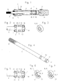
- FIG. 1 shows a longitudinal section by a working cylinder with the piston according to the invention
- Fig. 2 is an enlarged longitudinal section through the piston
- Fig. 3 Detail shown in perspective in view
- Fig. 4 is the view of the Piston rod shown in perspective
- Fig. 5 is a longitudinal section by a variant of the piston
- FIGS. 6 and 7 show two different ones Embodiments of a component of the piston in perspective Presentation
- Fig. 8 shows the working cylinder with a piston another embodiment of the invention in longitudinal section
- Fig. 9th in addition a longitudinal section through the piston
- FIG. 10 a perspective View of the main body of the piston
- 11 is another Longitudinal section through a working cylinder with another variant of the Piston according to the invention
- Fig. 12 is a longitudinal section through the Piston 6 shown enlarged.
- the working cylinder is designated 1, in this the piston 2 according to the invention is displaceable arranged.
- the working cylinder 1 consists of a cylinder tube 3, the at its ends on the one hand by a cylinder bottom 4 and on the other through a cylinder cover 5, through which the piston 2 connected piston rod 6 is led out of the cylinder tube 3, is completed.
- the connections for the supply and discharge of the pneumatic or hydraulic pressure medium are in the cylinder bottom 4 with 7 and designated 8 in the cylinder cover 5. Carrying out the piston rod 6 through the cylinder cover 5 is in the designs according to the 1 and 8 provided with a seal 9.
- the one-piece trained Piston rod 6 at its outer end with a thread 10 for connection to a device, not shown, to be driven is provided and at its other end, which is inside the cylinder barrel 3 lies, has two annular grooves 11 and 12 open on the outer circumference.
- the annular groove 12 is at the end of the piston rod 6 on its flank completed a disc-shaped ring section 14.
- a sealing ring 15 and 16 made of elastic material so-called "Snap seals" are used.
- a ring magnet 17 is placed, which is a non-contact scanning the respective piston position.
- guide rings 18 and 19 made of resistant material placed the cylindrical portion 13 of the piston rod 6.
- Fig. 3 shows such a guide ring 18 in a perspective view. How from 1 shows, the guide rings 18, 19 have a larger size Outside diameter than the ring magnet 17. They lie with their cylindrical On the outer edge of the cylinder tube 3 and thus form a safe Centering and guiding the piston 2 in the cylinder tube 3.
- the piston rod 6 is also made in one piece with two ring grooves 11 and 12 and provided with an annular portion 13.
- the ring grooves 11 and 12 are elastic sealing rings 15 and 16 inserted and on the cylindrical portion 13 is a Ring magnet 17.
- the two guide rings 18 and 19 are each with an inner shoulder 20 and 21 provided with which they on the both side flanks of the cylindrical section 13 of the piston rod 6 5, as can be seen from FIG.
- the guide rings 18, 19 are in for this purpose partially circular ring sections 22 and 23 divided.
- the in Fig. 7 Ring cutouts 22, 23 shown can be on the cylindrical portion 13 of the piston rod 6 placed loosely and to the guide ring 18,19 be put together. After inserting the piston 2 into the cylinder barrel 3, the guide rings 18, 19 are carried out without further measures the cylinder tube 3 held together.
- FIGS. 9 and 10 a base body 27, the ring grooves 11 and 12 for the sealing rings 14 and 15 and the cylindrical portion 13 for the ring magnet 17 has.
- the base body 27 with a protruding provided cylindrical collar, which forms the guide ring 18.
- Fig. 10 shows the one-piece base body 27.
- 11 and 12 finally show an embodiment with a single-acting cylinder 1.
- the piston rod 6 the same time the basic body of the piston 2 is only with one Sealing ring 16 provided in an annular groove 12 between a cylindrical Section 13 of the piston rod 6 and the narrow ring section 14 is inserted elastically at the end of the piston rod 6.
- the ring magnet 17 is pushed onto the one in it Embodiment considerably wider guide ring 18 connects.
- a connection 7 is provided, whereas in the area of Cylinder cover 5 only one ventilation channel 28 from the inside of the cylinder leads to the outside.
- the piston 2 On its side facing away from the sealing ring 16 the piston 2 is loaded by a return spring 29 which is concentric is arranged around the piston rod 6.
- the guide ring 18 is in the Area of the return spring 29 is provided with a recess 30 which the Return spring 29 in its compressed state at least partially records.
- the guide ring 18 a slightly larger outer diameter than the ring magnet 17 and lies on the inner wall of the cylinder tube 13 so that it is a guide and centering for the piston 2 in the working cylinder 1 forms.
- the Guide ring 18 thus prevents - just as with the others described Embodiments - too large a deformation of the sealing ring 16, which could damage it and proportionately would be subject to great wear. With inaccurate centering of the piston 2, it would also be possible for the sealing of the cylinder tube 3 is leaking through the elastic sealing ring 16.
Landscapes
- Engineering & Computer Science (AREA)
- Physics & Mathematics (AREA)
- Fluid Mechanics (AREA)
- Mechanical Engineering (AREA)
- General Engineering & Computer Science (AREA)
- Actuator (AREA)
Applications Claiming Priority (2)
| Application Number | Priority Date | Filing Date | Title |
|---|---|---|---|
| AT0187996A AT404290B (de) | 1996-10-28 | 1996-10-28 | Kolben für einen pneumatischen oder hydraulischen arbeitszylinder |
| AT1879/96 | 1996-10-28 |
Publications (2)
| Publication Number | Publication Date |
|---|---|
| EP0838616A2 true EP0838616A2 (fr) | 1998-04-29 |
| EP0838616A3 EP0838616A3 (fr) | 1998-05-13 |
Family
ID=3522996
Family Applications (1)
| Application Number | Title | Priority Date | Filing Date |
|---|---|---|---|
| EP97890197A Withdrawn EP0838616A3 (fr) | 1996-10-28 | 1997-10-03 | Piston pour un cylindre de travail pneumatique ou hydraulique |
Country Status (3)
| Country | Link |
|---|---|
| EP (1) | EP0838616A3 (fr) |
| AT (1) | AT404290B (fr) |
| CZ (1) | CZ343497A3 (fr) |
Cited By (2)
| Publication number | Priority date | Publication date | Assignee | Title |
|---|---|---|---|---|
| CN1828067B (zh) * | 2005-03-04 | 2010-10-13 | Smc株式会社 | 带位置检测机构的促动器 |
| CN110778715A (zh) * | 2019-12-02 | 2020-02-11 | 沈阳众磊道桥有限公司 | 一种动三轴仪用封水止水活塞 |
Families Citing this family (2)
| Publication number | Priority date | Publication date | Assignee | Title |
|---|---|---|---|---|
| DE10323797B4 (de) * | 2003-05-23 | 2005-05-25 | Zf Sachs Ag | Kolben-Zylinder-Aggregat mit einem Sensorsystem |
| CN112268034A (zh) * | 2020-10-29 | 2021-01-26 | 南京中远海运船舶设备配件有限公司 | 船用低速柴油机气阀生产用电热镦机精确运动砧子缸组件 |
Family Cites Families (10)
| Publication number | Priority date | Publication date | Assignee | Title |
|---|---|---|---|---|
| US3115071A (en) * | 1961-10-06 | 1963-12-24 | Hough Co Frank | Reciprocating hydraulic motor |
| AT280723B (de) * | 1968-05-17 | 1970-04-27 | Hoerbiger Ventilwerke Ag | Umsteuereinrichtung mit berührungsloser Abtastung für verschiebbare Maschinenteile, insbesondere für pneumatische und hydraulische Zylinder |
| DE2614263A1 (de) * | 1976-04-02 | 1977-10-13 | Walter Hunger | Dynamisch nachstellbare dichtungs- und fuehrungsvorrichtung |
| DE7722958U1 (de) * | 1977-07-22 | 1977-12-29 | Specken Ag, Urdorf (Schweiz) | Pneumatikzylinder mit berührungslosem Endschalter |
| SE419787B (sv) * | 1978-05-03 | 1981-08-24 | Hydro Pneumatic Ab | Arbetscylinder med kolvenhet och magnetiskt paverkbar indikeringsanordning |
| DE3015258C2 (de) * | 1980-04-21 | 1987-05-07 | Festo-Maschinenfabrik Gottlieb Stoll, 7300 Esslingen | Induktiver Kolbenstellungsgeber |
| JPS5876804U (ja) * | 1981-11-19 | 1983-05-24 | 焼結金属工業株式会社 | ロツドレスシリンダ |
| DE8209420U1 (de) * | 1982-04-02 | 1983-09-15 | Robert Bosch Gmbh, 7000 Stuttgart | Kolben fuer beruehrungslose abtastung der kolbenstellung |
| GB8718173D0 (en) * | 1987-07-31 | 1987-09-09 | Norgren Martonair Ltd | Sensing system |
| DE4122481C2 (de) * | 1991-07-06 | 1995-08-31 | Kuhnke Gmbh Kg H | Kolben-Zylinder-Anordnung |
-
1996
- 1996-10-28 AT AT0187996A patent/AT404290B/de not_active IP Right Cessation
-
1997
- 1997-10-03 EP EP97890197A patent/EP0838616A3/fr not_active Withdrawn
- 1997-10-29 CZ CZ973434A patent/CZ343497A3/cs unknown
Cited By (2)
| Publication number | Priority date | Publication date | Assignee | Title |
|---|---|---|---|---|
| CN1828067B (zh) * | 2005-03-04 | 2010-10-13 | Smc株式会社 | 带位置检测机构的促动器 |
| CN110778715A (zh) * | 2019-12-02 | 2020-02-11 | 沈阳众磊道桥有限公司 | 一种动三轴仪用封水止水活塞 |
Also Published As
| Publication number | Publication date |
|---|---|
| ATA187996A (de) | 1998-02-15 |
| CZ343497A3 (cs) | 1998-05-13 |
| EP0838616A3 (fr) | 1998-05-13 |
| AT404290B (de) | 1998-10-27 |
Similar Documents
| Publication | Publication Date | Title |
|---|---|---|
| DE19580456C1 (de) | Transportsicherung bei einem Kettenspanner | |
| DE112015004510B4 (de) | Fluidzylinder | |
| AT414033B (de) | Dämpfer, insbesondere für möbel | |
| EP0264682B2 (fr) | Agrégat à piston-cylindre | |
| DE19950582B9 (de) | Betätigungsvorrichtung für ein drehbares Verschlussteil eines Ventils | |
| EP0164792B1 (fr) | Dispositif pour l'accouplement positif de deux arbres | |
| DE2847274C2 (de) | Kolben für einen Arbeitszylinder | |
| DE8906987U1 (de) | Dichtungsvorrichtung für triebstangenfreie pneumatische Zylinder | |
| DE19580861B4 (de) | Hydraulisches Spielausgleichselement für die Ventilsteuerung von Brennkraftmaschinen | |
| DE102013001650A1 (de) | Zylinder-Kolben-Einheit mit Kolbendrossel | |
| DE202005005508U1 (de) | Kolben und damit ausgestattete fluidbetätigte Stellvorrichtung | |
| DE60107117T2 (de) | Anbohranschlussstück | |
| DE3404095C2 (de) | Kolben für einen Arbeitszylinder | |
| DE2609817C3 (de) | Kolben, insbesondere für einen Pneumatikzylinder | |
| EP0838616A2 (fr) | Piston pour un cylindre de travail pneumatique ou hydraulique | |
| DE19843253C2 (de) | Druckmittelzylinder mit einem Zylinderrohr | |
| DE19542513C2 (de) | Hohle Kolbenstange für ein Kolben-Zylinderaggregat | |
| DE10156507B4 (de) | Hydraulische Spanneinrichtung für einen Ketten- oder Riementrieb | |
| DE19837579A1 (de) | Wälzlager | |
| WO2010108589A1 (fr) | Tube de carter et entraînement linéaire équipé de ce dernier | |
| DE4300004C2 (de) | Anschlußarmatur für Rohre | |
| DE29814578U1 (de) | Linearantrieb | |
| DE2905724C2 (de) | Stangen-Dichtung | |
| DE3719155A1 (de) | In einem gehaeuse untergebrachte sicherheitsklemmvorrichtung zum verklemmen der kolbenstange eines hubzylinders | |
| DE4011119A1 (de) | Kolben-zylinder-aggregat |
Legal Events
| Date | Code | Title | Description |
|---|---|---|---|
| PUAI | Public reference made under article 153(3) epc to a published international application that has entered the european phase |
Free format text: ORIGINAL CODE: 0009012 |
|
| PUAL | Search report despatched |
Free format text: ORIGINAL CODE: 0009013 |
|
| AK | Designated contracting states |
Kind code of ref document: A2 Designated state(s): AT DE ES FR GB IT |
|
| AX | Request for extension of the european patent |
Free format text: AL;LT;LV;RO;SI |
|
| AK | Designated contracting states |
Kind code of ref document: A3 Designated state(s): AT BE CH DE DK ES FI FR GB GR IE IT LI LU MC NL PT SE |
|
| AX | Request for extension of the european patent |
Free format text: AL;LT;LV;RO;SI |
|
| 17P | Request for examination filed |
Effective date: 19980626 |
|
| AKX | Designation fees paid |
Free format text: AT DE ES FR GB IT |
|
| RBV | Designated contracting states (corrected) |
Designated state(s): AT DE ES FR GB IT |
|
| STAA | Information on the status of an ep patent application or granted ep patent |
Free format text: STATUS: THE APPLICATION IS DEEMED TO BE WITHDRAWN |
|
| 18D | Application deemed to be withdrawn |
Effective date: 20000503 |