EP0838621A2 - Knebelbetägtigtes Ventil - Google Patents
Knebelbetägtigtes Ventil Download PDFInfo
- Publication number
- EP0838621A2 EP0838621A2 EP97111667A EP97111667A EP0838621A2 EP 0838621 A2 EP0838621 A2 EP 0838621A2 EP 97111667 A EP97111667 A EP 97111667A EP 97111667 A EP97111667 A EP 97111667A EP 0838621 A2 EP0838621 A2 EP 0838621A2
- Authority
- EP
- European Patent Office
- Prior art keywords
- valve stem
- valve
- operation member
- tapered surface
- toggle
- Prior art date
- Legal status (The legal status is an assumption and is not a legal conclusion. Google has not performed a legal analysis and makes no representation as to the accuracy of the status listed.)
- Granted
Links
- 238000006073 displacement reaction Methods 0.000 claims abstract description 16
- 239000012530 fluid Substances 0.000 claims description 21
- 230000006835 compression Effects 0.000 description 12
- 238000007906 compression Methods 0.000 description 12
- 239000002184 metal Substances 0.000 description 9
- 230000002093 peripheral effect Effects 0.000 description 3
- 238000000926 separation method Methods 0.000 description 2
Images



Classifications
-
- F—MECHANICAL ENGINEERING; LIGHTING; HEATING; WEAPONS; BLASTING
- F15—FLUID-PRESSURE ACTUATORS; HYDRAULICS OR PNEUMATICS IN GENERAL
- F15B—SYSTEMS ACTING BY MEANS OF FLUIDS IN GENERAL; FLUID-PRESSURE ACTUATORS, e.g. SERVOMOTORS; DETAILS OF FLUID-PRESSURE SYSTEMS, NOT OTHERWISE PROVIDED FOR
- F15B13/00—Details of servomotor systems ; Valves for servomotor systems
- F15B13/02—Fluid distribution or supply devices characterised by their adaptation to the control of servomotors
-
- F—MECHANICAL ENGINEERING; LIGHTING; HEATING; WEAPONS; BLASTING
- F16—ENGINEERING ELEMENTS AND UNITS; GENERAL MEASURES FOR PRODUCING AND MAINTAINING EFFECTIVE FUNCTIONING OF MACHINES OR INSTALLATIONS; THERMAL INSULATION IN GENERAL
- F16K—VALVES; TAPS; COCKS; ACTUATING-FLOATS; DEVICES FOR VENTING OR AERATING
- F16K31/00—Actuating devices; Operating means; Releasing devices
- F16K31/12—Actuating devices; Operating means; Releasing devices actuated by fluid
- F16K31/16—Actuating devices; Operating means; Releasing devices actuated by fluid with a mechanism, other than pulling-or pushing-rod, between fluid motor and closure member
- F16K31/163—Actuating devices; Operating means; Releasing devices actuated by fluid with a mechanism, other than pulling-or pushing-rod, between fluid motor and closure member the fluid acting on a piston
-
- Y—GENERAL TAGGING OF NEW TECHNOLOGICAL DEVELOPMENTS; GENERAL TAGGING OF CROSS-SECTIONAL TECHNOLOGIES SPANNING OVER SEVERAL SECTIONS OF THE IPC; TECHNICAL SUBJECTS COVERED BY FORMER USPC CROSS-REFERENCE ART COLLECTIONS [XRACs] AND DIGESTS
- Y10—TECHNICAL SUBJECTS COVERED BY FORMER USPC
- Y10T—TECHNICAL SUBJECTS COVERED BY FORMER US CLASSIFICATION
- Y10T74/00—Machine element or mechanism
- Y10T74/18—Mechanical movements
- Y10T74/18992—Reciprocating to reciprocating
-
- Y—GENERAL TAGGING OF NEW TECHNOLOGICAL DEVELOPMENTS; GENERAL TAGGING OF CROSS-SECTIONAL TECHNOLOGIES SPANNING OVER SEVERAL SECTIONS OF THE IPC; TECHNICAL SUBJECTS COVERED BY FORMER USPC CROSS-REFERENCE ART COLLECTIONS [XRACs] AND DIGESTS
- Y10—TECHNICAL SUBJECTS COVERED BY FORMER USPC
- Y10T—TECHNICAL SUBJECTS COVERED BY FORMER US CLASSIFICATION
- Y10T74/00—Machine element or mechanism
- Y10T74/20—Control lever and linkage systems
- Y10T74/20558—Variable output force
-
- Y—GENERAL TAGGING OF NEW TECHNOLOGICAL DEVELOPMENTS; GENERAL TAGGING OF CROSS-SECTIONAL TECHNOLOGIES SPANNING OVER SEVERAL SECTIONS OF THE IPC; TECHNICAL SUBJECTS COVERED BY FORMER USPC CROSS-REFERENCE ART COLLECTIONS [XRACs] AND DIGESTS
- Y10—TECHNICAL SUBJECTS COVERED BY FORMER USPC
- Y10T—TECHNICAL SUBJECTS COVERED BY FORMER US CLASSIFICATION
- Y10T74/00—Machine element or mechanism
- Y10T74/21—Elements
- Y10T74/2101—Cams
- Y10T74/2107—Follower
Definitions
- the present invention relates to a toggle valve (high pressure valve) in which operational force is increased and transmitted to a valve stem which actuates a valve body.
- toggle valves There are various known types of toggle valves. However, known toggle valves are large and elements thereof must be machined at extremely high precision. Moreover, it is difficult for known toggle valves to maintain stable operation for long periods of time.
- a toggle valve comprising a valve stem which is slidably supported by a housing and which moves a valve body away from and toward a valve seat, an operation member separate from the valve stem, which is supported by the housing to slide in a direction parallel to the axis of the valve stem, a valve stem roller member which is supported by the valve stem and which has a shaft whose axis extends in a direction perpendicular to the direction of the sliding movement of the valve stem without intersecting the axis of the valve stem, a tapered surface provided on the end of the operation member adjacent to the valve stem, and an intermediate roller member which has a shaft extending parallel with the axis of the valve stem roller member and which is provided between the tapered surface of the operation member and the valve stem roller member to come into contact with the tapered surface and the valve stem roller member.
- the above mentioned tapered surface, intermediate roller member and valve stem roller member are arranged such that when the operation member is moved by a unit displacement toward the valve stem in order to move the valve stem toward the valve seat through the tapered surface, the intermediate roller member, and the valve stem roller member, the valve stem is moved by a displacement smaller than that of the operation member.
- the toggle valve further comprises a plurality of valve stem rollers and intermediate roller members, which are provided in a rotation symmetry with respect to the axis of the valve member.
- valve stem and the valve stem roller members comprise a valve stem assembly, and the valve stem is coaxial to the operation member.
- the force to move the operation member toward the valve stem can be produced by a spring and the force to move the operation member away from the valve stem produced by fluid pressure, or the force to move the operation member toward the valve stem can be produced by fluid pressure, and the force to move the operation member away from the valve stem produced by a spring.
- the tapered surface can be made of a conical surface or a wedge-like surface.
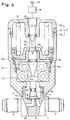
- a fluid passage block 11 is comprised of a pair of passage connectors 12 and 13 aligned along the same axis and a valve connector 14 which extends perpendicularly to the axis of the passage connectors 12 and 13.
- the passage connectors 12 and 13 are respectively provided therein with fluid passages 12a and 13a which open into the valve connector 14.
- An annular valve seat 15 is provided at the open end of fluid passage 12a.
- the valve connector 14 is provided with a circular metal diaphragm 16 which covers the annular valve seat 15 and the open end of the fluid passage 13a, a retainer 17 which holds the metal diaphragm 16 at the peripheral edge thereof, and an opening and closing valve body 18 which is movably supported by the retainer 17.
- the fluid passage 12a is adapted to supply high-pressure fluid
- the annular valve seat 15 is located at the center of the metal diaphragm 16.
- the valve body 18 can be moved toward and away from the center portion of the metal diaphragm 16.
- a lower housing 21a of a housing 21 of a toggle valve 20 is attached to the outer peripheral surface of the valve connector 14 by means of an external thread 14a formed on the outer peripheral surface of the valve connector 14.
- the housing 21 is comprised of the lower housing 21a and an upper housing 21b connected to the lower housing 21a by means of a lock ring 21c.
- a valve stem assembly 24, a pair of intermediate rollers 25, and an operation member 26 are inserted and supported as movable components in the housing 21 in this order from the lower end thereof in Figs. 1 and 2.
- the valve stem assembly 24 is comprised of a valve stem 22 which moves the valve body 18 away from and towards the annular valve seat 15 and a pair of valve stem roller members 23.
- the valve stem roller members 23 are each provided with a roller 23a which has a shaft 23b inserted in its center
- the shaft 23b is supported by a support plate 22a which is integral with and perpendicular to the valve stem 22.
- the valve stem roller members 23 (shafts 23b) are parallel to each other and are located in a rotation symmetry with respect to the axis of the valve stem 22.
- valve stem roller members 23 extend perpendicular to the axis of the valve stem 22 without intersecting the same.
- the valve stem assembly 24 is biased by a compression spring 24a in the direction to move the valve stem 22 away from the metal diaphragm 16.
- the operation member 26 is comprised of an operation shaft 27 coaxial to the valve stem 22, a piston member 28 integrally connected to an intermediate portion of the operation shaft 27, and a spring receiving piston member 29 integrally connected to the upper end of the operation shaft 27.
- the piston member 28 defines a valve opening pressure chamber 31a between the piston member 28 and a stationary separation wall 30 in the housing 21.
- the spring receiving piston chamber 29 defines another valve opening pressure chamber 31b between the piston member 29 and a stationary stop plate 32.
- the upper moving end of the piston member 28 in Fig. 1 is restricted by the stationary stop plate 32 in the housing 21 when the piston member 28 abuts against the stop plate 32.
- a pilot pressure P is exerted by a pilot pressure source 36 on the valve opening pressure chambers 31a and 31b through radial passage 33b and axial passage 33a, formed in the operation shaft 27, a pilot pressure introduction port 34 of the upper housing 21b and an opening and closing control valve 35.
- a compression spring 37 is provided between the spring receiving piston member 29 and the upper housing 21b to continuously bias the operation member 26 toward the valve stem assembly 24.
- a tapered surface portion 27a is provided on the front end (lower end in Fig.1) of the operation shaft 27 of the operation member 26.
- the pair of intermediate rollers 25 are provided between the tapered surface 27a and the valve stem roller members 23 of the valve stem assembly 24.
- the tapered surface 27a can be formed by a conical surface 27a1 as shown in Fig. 3, or a wedge-like surface consisting of a pair of oblique flat surfaces 27a2 as shown in Fig. 4.
- the compression spring 37 is sufficiently stronger than the compression spring 24a.
- the intermediate rollers (idle roller members) 25 are each provided with a roller 25a which has a shaft 25b inserted in it.
- the rollers 25a are received in a recess 30a formed in the lower end of the stationary wall 30 so as to rotate but not to move in the axial direction.
- the shafts 25b are rotatably and slidably supported on a lower guide surface 30b of the stationary separation wall 30.
- the idle roller members 25 are parallel with the valve stem rollers 23 and are located between the tapered surface 27a of the operation shaft 27 and the valve stem roller members 23.
- the valve closing downward pressure acting on the operation member 26 is transmitted to the valve stem 22 through the tapered surface 27a, the intermediate rollers 25, the valve stem roller members 23 and the support plate 22a.
- the valve stem roller members 23 and the intermediate rollers 25 can be made of, for example, commercially available needle bearings which are inexpensive and have high precision.
- the taper angle of the tapered surface 27a of the operation shaft 27 and the outer diameters and the initial positions of the intermediate rollers 25 and the valve stem roller members 23 are determined as follows. Namely, when the operation member 26 is moved toward the valve stem assembly 24 by a unit displacement, subsequently moving the valve stem 22 toward the annular valve seat 15 through the tapered surface 27a, the intermediate rollers 25 and the valve stem roller members 23, the valve stem 22 is moved by a displacement smaller than the unit displacement of the operation member 26.
- the toggle valve constructed as above operates as follows.
- valve stem 22 Since the displacement of the valve stem 22 is smaller than the unit displacement of the operation member 26 when the valve closing force of the operation member 26 is transmitted to the valve stem 22 through the tapered surface 25, the intermediate rollers 25 and the valve stem roller members 23, it is possible to obtain a strong valve closing force by a small spring force from the compression spring 37. In the examples mentioned above, a valve closing force five or ten times the spring force of the compression spring 37 is obtained.
- the opening and closing control valve 35 is opened to introduce the pilot pressure from the pilot pressure source 36 into the valve opening chambers 31a and 31b through the axial passage 33a and the radial passage 33b of the operation shaft 27.
- the pilot pressure exceeds the spring force of the compression spring 37, the upward movement of the operation member 26 takes place, and subsequently the force to retain the valve body 18 in the closed position disappears.
- the deformation of the metal diaphragm 16 occurs due to the pressure within the fluid passage 12a, so that a fluid connection can be established between the fluid passages 12a and 13a (Fig. 2).
- the above-mentioned embodiment is applied to a normally closed type valve in which the valve closing force is produced by the compression spring.
- the present invention can be applied to a normally open type valve in which the valve closing force is produced by the pilot pressure, as shown in Fig. 5.
- Fig. 5 there is no compression spring 37 shown in Figs. 1 and 2, and the chamber 31' in which the compression spring 37 is housed in Figs. 1 and 2 serves as a pilot pressure chamber.
- the compression spring 37R is provided, for example, in the pilot pressure chamber 31a shown in Figs. 1 and 2 to obtain the valve opening force.
- valve stem 22 and the valve body 18 are made of separate pieces in the illustrated embodiments, it is possible to make them a single piece.
- the presence or absence of an intermediate member such as the metal diaphragm 16 between the valve body 18 and the annular valve seat 15 is determined in accordance with the kind or properties of the fluid to be fed through the fluid passages 12a and 13a.
- the valve assembly 24 is provided with a pair of valve stem roller members 23 in the illustrated embodiments, it is possible to provide more than two valve stem roller members which are spaced in the circumferential direction preferably at an equiangular distance around the shaft 22.
- Figs. 6 and 7 show a further embodiment of the present invention.
- the further embodiment is different from the embodiment shown in Figs. 1 through 4 by the following points.
- a single piston 29 is employed instead of a double-piston in the embodiment of Figs. 1 and 2.
- the piston 28 in Figs. 1 and 2 is deleted.
- the taper angle of the surface 27a of the operational shaft is smaller than that shown in Figs. 1 through 4.
- the tapered surface 27a is arranged such that a larger displacement of the operational member 27 causes a proportionally smaller displacement of the valve stem roller member 23, hence a larger power is obtained to close the valve.
- the toggle mechanism is realized by the tapered surface portion of the operation member, the intermediate rollers, and the valve stem rollers.
- Commercially available needle bearings which are inexpensive and can be precisely machined can be used as the rollers.
- an inexpensive, reliable and durable toggle valve can be provided.
Landscapes
- Engineering & Computer Science (AREA)
- General Engineering & Computer Science (AREA)
- Mechanical Engineering (AREA)
- Physics & Mathematics (AREA)
- Fluid Mechanics (AREA)
- Mechanically-Actuated Valves (AREA)
- Fluid-Driven Valves (AREA)
- Multiple-Way Valves (AREA)
- Lift Valve (AREA)
Applications Claiming Priority (3)
| Application Number | Priority Date | Filing Date | Title |
|---|---|---|---|
| JP26316596A JP3392301B2 (ja) | 1996-10-03 | 1996-10-03 | 倍力開閉弁 |
| JP26316596 | 1996-10-03 | ||
| JP263165/96 | 1996-10-03 |
Publications (3)
| Publication Number | Publication Date |
|---|---|
| EP0838621A2 true EP0838621A2 (de) | 1998-04-29 |
| EP0838621A3 EP0838621A3 (de) | 1998-09-23 |
| EP0838621B1 EP0838621B1 (de) | 2002-10-02 |
Family
ID=17385688
Family Applications (1)
| Application Number | Title | Priority Date | Filing Date |
|---|---|---|---|
| EP97111667A Expired - Lifetime EP0838621B1 (de) | 1996-10-03 | 1997-07-09 | Knebelbetägtigtes Ventil |
Country Status (6)
| Country | Link |
|---|---|
| US (1) | US5906353A (de) |
| EP (1) | EP0838621B1 (de) |
| JP (1) | JP3392301B2 (de) |
| KR (1) | KR100416495B1 (de) |
| DE (2) | DE69716007T2 (de) |
| TW (1) | TW348209B (de) |
Families Citing this family (14)
| Publication number | Priority date | Publication date | Assignee | Title |
|---|---|---|---|---|
| US6607178B1 (en) * | 1997-09-29 | 2003-08-19 | Siemens Aktiengesellschaft | Thrust device, fuel injection valve having such a device, and method for manufacturing a thrust transfer element |
| JP3437811B2 (ja) * | 1999-05-12 | 2003-08-18 | 藤倉ゴム工業株式会社 | 二段階切換開閉弁及び倍力型二段階切換開閉弁 |
| JP3300686B2 (ja) * | 1999-07-16 | 2002-07-08 | 藤倉ゴム工業株式会社 | 多段ピストンアクチュエータ |
| US6637723B1 (en) * | 2001-09-06 | 2003-10-28 | Entegris, Inc. | Fluid valve |
| JP4133272B2 (ja) * | 2002-12-03 | 2008-08-13 | 藤倉ゴム工業株式会社 | ガスボンベ用空気作動常閉弁のロック機構 |
| JP4529023B2 (ja) * | 2002-12-03 | 2010-08-25 | 株式会社フジキン | 制御器 |
| AU2003211853A1 (en) * | 2003-03-07 | 2004-09-28 | Ckd Corporation | Flow control valve |
| JP2006523810A (ja) * | 2003-04-14 | 2006-10-19 | スワゲロック カンパニー | ダイヤフラムバルブシート |
| AU2003903803A0 (en) * | 2003-07-23 | 2003-08-07 | Goyen Controls Co Pty Ltd | Poppet type flow control valve |
| JP2005325893A (ja) * | 2004-05-13 | 2005-11-24 | Fujikin Inc | 制御器 |
| CN1704615A (zh) * | 2004-06-01 | 2005-12-07 | 斯瓦戈洛克公司 | 流体致动器 |
| US9377110B2 (en) * | 2012-09-26 | 2016-06-28 | Fisher Controls International Llc | Fluid control valve having an adjustable valve stem and piston assembly |
| JP7015111B2 (ja) * | 2017-01-31 | 2022-02-08 | 株式会社キッツエスシーティー | バルブ用アクチュエータとこれを備えたダイヤフラムバルブ |
| JP7636037B2 (ja) * | 2021-07-30 | 2025-02-26 | 株式会社フジキン | バルブ装置 |
Family Cites Families (14)
| Publication number | Priority date | Publication date | Assignee | Title |
|---|---|---|---|---|
| US2395223A (en) * | 1944-01-13 | 1946-02-19 | Automatic Shifters Inc | Vehicle brake mechanism |
| DE2705914C2 (de) * | 1977-02-09 | 1982-06-16 | Siemens AG, 1000 Berlin und 8000 München | Umsteuerventil |
| DE7830221U1 (de) * | 1978-10-11 | 1980-03-20 | Arnold, Franz, 8960 Kempten | Mechanischer kraftverstaerker |
| US4609178A (en) * | 1984-02-02 | 1986-09-02 | Baumann Hans D | Diaphragm type control valve |
| US4549719A (en) * | 1984-02-02 | 1985-10-29 | Baumann Hans D | Mechanical amplifying means for valves and other devices |
| FR2565667B1 (fr) * | 1984-06-06 | 1989-07-07 | Madec Mater | Robinet a gaz perfectionne pour l'alimentation d'un bruleur. |
| NO158552C (no) * | 1986-04-04 | 1988-09-28 | Skarpenord Control Systems As | Enkeltvirkende hydraulisk aktuator for uttak av lagret fjaerenergi. |
| US4684103A (en) * | 1986-08-25 | 1987-08-04 | Baumann Hans D | Lever-amplified actuating means for valves and other devices |
| US4875404A (en) * | 1988-07-05 | 1989-10-24 | Ewal Manufacturing Co., Inc. | Compact fluid powered actuator |
| US4871143A (en) * | 1989-02-15 | 1989-10-03 | Cameron Iron Works Usa, Inc. | Gate valve with supplemental actuator |
| JPH086828B2 (ja) * | 1991-08-09 | 1996-01-29 | 株式会社ベンカン | メタルダイヤフラム弁 |
| US5215286A (en) * | 1992-05-26 | 1993-06-01 | Nupro Company | High pressure diaphragm valve |
| JP3338972B2 (ja) * | 1993-11-12 | 2002-10-28 | 清原 まさ子 | 制御器 |
| JP3616855B2 (ja) * | 1995-03-13 | 2005-02-02 | 株式会社フジキン | 制御器 |
-
1996
- 1996-10-03 JP JP26316596A patent/JP3392301B2/ja not_active Expired - Fee Related
-
1997
- 1997-07-04 KR KR1019970031131A patent/KR100416495B1/ko not_active Expired - Fee Related
- 1997-07-08 US US08/889,408 patent/US5906353A/en not_active Expired - Lifetime
- 1997-07-09 EP EP97111667A patent/EP0838621B1/de not_active Expired - Lifetime
- 1997-07-09 DE DE69716007T patent/DE69716007T2/de not_active Expired - Lifetime
- 1997-07-09 DE DE0838621T patent/DE838621T1/de active Pending
- 1997-07-14 TW TW086109897A patent/TW348209B/zh not_active IP Right Cessation
Non-Patent Citations (1)
| Title |
|---|
| None |
Also Published As
| Publication number | Publication date |
|---|---|
| EP0838621A3 (de) | 1998-09-23 |
| KR19980032212A (ko) | 1998-07-25 |
| DE69716007D1 (de) | 2002-11-07 |
| TW348209B (en) | 1998-12-21 |
| DE69716007T2 (de) | 2003-10-09 |
| JP3392301B2 (ja) | 2003-03-31 |
| JPH10110856A (ja) | 1998-04-28 |
| US5906353A (en) | 1999-05-25 |
| EP0838621B1 (de) | 2002-10-02 |
| DE838621T1 (de) | 1998-10-22 |
| KR100416495B1 (ko) | 2004-04-03 |
Similar Documents
| Publication | Publication Date | Title |
|---|---|---|
| US5906353A (en) | Toggle valve | |
| JP2556972B2 (ja) | バルブ | |
| WO1996001445A1 (en) | A fluid pressure regulator | |
| US5090747A (en) | Coupling socket | |
| US20090302256A1 (en) | Pressure reducing valve | |
| US4319734A (en) | Valve | |
| EP1031901A1 (de) | Regler | |
| EP2184523A1 (de) | Steuerventil | |
| EP1031900B1 (de) | Regler | |
| US4945817A (en) | Axial piston device | |
| US20130167712A1 (en) | Cylinder | |
| EP1426626B1 (de) | Blockiervorrichtung für ein Ventil | |
| US5558121A (en) | Fluid actuated ball check valve assembly | |
| US6805158B2 (en) | Apparatus for visually checking the operational status of a stop valve, and a manual opening apparatus for a normally-closed valve | |
| US8662469B2 (en) | Power assisted on/off valve | |
| JP3452474B2 (ja) | バランス形リリーフ弁 | |
| US20240392880A1 (en) | Insert arrangement, control valve and process plant | |
| US4927114A (en) | Tilt valve cartridge | |
| JP4100924B2 (ja) | 容量制御弁 | |
| JP3429436B2 (ja) | 開閉弁の状態表示装置 | |
| JPH03605Y2 (de) | ||
| LU505967B1 (en) | Device for controlling flow or pressure of gas in a cylinder with optimised refill port and pressure indicator | |
| CN223985406U (zh) | 电子膨胀阀 | |
| JP4100925B2 (ja) | 容量制御弁 | |
| JPH0723664Y2 (ja) | 圧力制御弁 |
Legal Events
| Date | Code | Title | Description |
|---|---|---|---|
| PUAI | Public reference made under article 153(3) epc to a published international application that has entered the european phase |
Free format text: ORIGINAL CODE: 0009012 |
|
| AK | Designated contracting states |
Kind code of ref document: A2 Designated state(s): AT BE CH DE DK ES FI FR GB GR IE IT LI LU MC NL PT SE |
|
| AX | Request for extension of the european patent |
Free format text: AL;LT;LV;RO;SI |
|
| EL | Fr: translation of claims filed | ||
| PUAL | Search report despatched |
Free format text: ORIGINAL CODE: 0009013 |
|
| AK | Designated contracting states |
Kind code of ref document: A3 Designated state(s): AT BE CH DE DK ES FI FR GB GR IE IT LI LU MC NL PT SE |
|
| AX | Request for extension of the european patent |
Free format text: AL;LT;LV;RO;SI |
|
| DET | De: translation of patent claims | ||
| 17P | Request for examination filed |
Effective date: 19981117 |
|
| AKX | Designation fees paid | ||
| RBV | Designated contracting states (corrected) | ||
| RBV | Designated contracting states (corrected) |
Designated state(s): DE FR GB |
|
| 17Q | First examination report despatched |
Effective date: 20001221 |
|
| GRAG | Despatch of communication of intention to grant |
Free format text: ORIGINAL CODE: EPIDOS AGRA |
|
| GRAG | Despatch of communication of intention to grant |
Free format text: ORIGINAL CODE: EPIDOS AGRA |
|
| GRAH | Despatch of communication of intention to grant a patent |
Free format text: ORIGINAL CODE: EPIDOS IGRA |
|
| GRAH | Despatch of communication of intention to grant a patent |
Free format text: ORIGINAL CODE: EPIDOS IGRA |
|
| GRAA | (expected) grant |
Free format text: ORIGINAL CODE: 0009210 |
|
| AK | Designated contracting states |
Kind code of ref document: B1 Designated state(s): DE FR GB |
|
| REG | Reference to a national code |
Ref country code: GB Ref legal event code: FG4D |
|
| REF | Corresponds to: |
Ref document number: 69716007 Country of ref document: DE Date of ref document: 20021107 |
|
| ET | Fr: translation filed | ||
| PLBE | No opposition filed within time limit |
Free format text: ORIGINAL CODE: 0009261 |
|
| STAA | Information on the status of an ep patent application or granted ep patent |
Free format text: STATUS: NO OPPOSITION FILED WITHIN TIME LIMIT |
|
| 26N | No opposition filed |
Effective date: 20030703 |
|
| PGFP | Annual fee paid to national office [announced via postgrant information from national office to epo] |
Ref country code: GB Payment date: 20120723 Year of fee payment: 16 |
|
| PGFP | Annual fee paid to national office [announced via postgrant information from national office to epo] |
Ref country code: FR Payment date: 20120803 Year of fee payment: 16 Ref country code: DE Payment date: 20120828 Year of fee payment: 16 |
|
| GBPC | Gb: european patent ceased through non-payment of renewal fee |
Effective date: 20130709 |
|
| REG | Reference to a national code |
Ref country code: FR Ref legal event code: ST Effective date: 20140331 |
|
| PG25 | Lapsed in a contracting state [announced via postgrant information from national office to epo] |
Ref country code: DE Free format text: LAPSE BECAUSE OF NON-PAYMENT OF DUE FEES Effective date: 20140201 Ref country code: GB Free format text: LAPSE BECAUSE OF NON-PAYMENT OF DUE FEES Effective date: 20130709 |
|
| REG | Reference to a national code |
Ref country code: DE Ref legal event code: R119 Ref document number: 69716007 Country of ref document: DE Effective date: 20140201 |
|
| PG25 | Lapsed in a contracting state [announced via postgrant information from national office to epo] |
Ref country code: FR Free format text: LAPSE BECAUSE OF NON-PAYMENT OF DUE FEES Effective date: 20130731 |