EP0838647A2 - Production cryogénique à trois colonnes d'oxygène impur et d'azote pur - Google Patents
Production cryogénique à trois colonnes d'oxygène impur et d'azote pur Download PDFInfo
- Publication number
- EP0838647A2 EP0838647A2 EP97308318A EP97308318A EP0838647A2 EP 0838647 A2 EP0838647 A2 EP 0838647A2 EP 97308318 A EP97308318 A EP 97308318A EP 97308318 A EP97308318 A EP 97308318A EP 0838647 A2 EP0838647 A2 EP 0838647A2
- Authority
- EP
- European Patent Office
- Prior art keywords
- pressure
- oxygen
- column
- pressure column
- feed air
- Prior art date
- Legal status (The legal status is an assumption and is not a legal conclusion. Google has not performed a legal analysis and makes no representation as to the accuracy of the status listed.)
- Granted
Links
Images



Classifications
-
- F—MECHANICAL ENGINEERING; LIGHTING; HEATING; WEAPONS; BLASTING
- F25—REFRIGERATION OR COOLING; COMBINED HEATING AND REFRIGERATION SYSTEMS; HEAT PUMP SYSTEMS; MANUFACTURE OR STORAGE OF ICE; LIQUEFACTION SOLIDIFICATION OF GASES
- F25J—LIQUEFACTION, SOLIDIFICATION OR SEPARATION OF GASES OR GASEOUS OR LIQUEFIED GASEOUS MIXTURES BY PRESSURE AND COLD TREATMENT OR BY BRINGING THEM INTO THE SUPERCRITICAL STATE
- F25J3/00—Processes or apparatus for separating the constituents of gaseous or liquefied gaseous mixtures involving the use of liquefaction or solidification
- F25J3/02—Processes or apparatus for separating the constituents of gaseous or liquefied gaseous mixtures involving the use of liquefaction or solidification by rectification, i.e. by continuous interchange of heat and material between a vapour stream and a liquid stream
- F25J3/04—Processes or apparatus for separating the constituents of gaseous or liquefied gaseous mixtures involving the use of liquefaction or solidification by rectification, i.e. by continuous interchange of heat and material between a vapour stream and a liquid stream for air
- F25J3/04006—Providing pressurised feed air or process streams within or from the air fractionation unit
- F25J3/04078—Providing pressurised feed air or process streams within or from the air fractionation unit providing pressurized products by liquid compression and vaporisation with cold recovery, i.e. so-called internal compression
- F25J3/04103—Providing pressurised feed air or process streams within or from the air fractionation unit providing pressurized products by liquid compression and vaporisation with cold recovery, i.e. so-called internal compression using solely hydrostatic liquid head
-
- F—MECHANICAL ENGINEERING; LIGHTING; HEATING; WEAPONS; BLASTING
- F25—REFRIGERATION OR COOLING; COMBINED HEATING AND REFRIGERATION SYSTEMS; HEAT PUMP SYSTEMS; MANUFACTURE OR STORAGE OF ICE; LIQUEFACTION SOLIDIFICATION OF GASES
- F25J—LIQUEFACTION, SOLIDIFICATION OR SEPARATION OF GASES OR GASEOUS OR LIQUEFIED GASEOUS MIXTURES BY PRESSURE AND COLD TREATMENT OR BY BRINGING THEM INTO THE SUPERCRITICAL STATE
- F25J3/00—Processes or apparatus for separating the constituents of gaseous or liquefied gaseous mixtures involving the use of liquefaction or solidification
- F25J3/02—Processes or apparatus for separating the constituents of gaseous or liquefied gaseous mixtures involving the use of liquefaction or solidification by rectification, i.e. by continuous interchange of heat and material between a vapour stream and a liquid stream
- F25J3/04—Processes or apparatus for separating the constituents of gaseous or liquefied gaseous mixtures involving the use of liquefaction or solidification by rectification, i.e. by continuous interchange of heat and material between a vapour stream and a liquid stream for air
- F25J3/04006—Providing pressurised feed air or process streams within or from the air fractionation unit
- F25J3/04078—Providing pressurised feed air or process streams within or from the air fractionation unit providing pressurized products by liquid compression and vaporisation with cold recovery, i.e. so-called internal compression
- F25J3/0409—Providing pressurised feed air or process streams within or from the air fractionation unit providing pressurized products by liquid compression and vaporisation with cold recovery, i.e. so-called internal compression of oxygen
-
- F—MECHANICAL ENGINEERING; LIGHTING; HEATING; WEAPONS; BLASTING
- F25—REFRIGERATION OR COOLING; COMBINED HEATING AND REFRIGERATION SYSTEMS; HEAT PUMP SYSTEMS; MANUFACTURE OR STORAGE OF ICE; LIQUEFACTION SOLIDIFICATION OF GASES
- F25J—LIQUEFACTION, SOLIDIFICATION OR SEPARATION OF GASES OR GASEOUS OR LIQUEFIED GASEOUS MIXTURES BY PRESSURE AND COLD TREATMENT OR BY BRINGING THEM INTO THE SUPERCRITICAL STATE
- F25J3/00—Processes or apparatus for separating the constituents of gaseous or liquefied gaseous mixtures involving the use of liquefaction or solidification
- F25J3/02—Processes or apparatus for separating the constituents of gaseous or liquefied gaseous mixtures involving the use of liquefaction or solidification by rectification, i.e. by continuous interchange of heat and material between a vapour stream and a liquid stream
- F25J3/04—Processes or apparatus for separating the constituents of gaseous or liquefied gaseous mixtures involving the use of liquefaction or solidification by rectification, i.e. by continuous interchange of heat and material between a vapour stream and a liquid stream for air
- F25J3/04151—Purification and (pre-)cooling of the feed air; recuperative heat-exchange with product streams
- F25J3/04187—Cooling of the purified feed air by recuperative heat-exchange; Heat-exchange with product streams
- F25J3/04193—Division of the main heat exchange line in consecutive sections having different functions
- F25J3/04206—Division of the main heat exchange line in consecutive sections having different functions including a so-called "auxiliary vaporiser" for vaporising and producing a gaseous product
-
- F—MECHANICAL ENGINEERING; LIGHTING; HEATING; WEAPONS; BLASTING
- F25—REFRIGERATION OR COOLING; COMBINED HEATING AND REFRIGERATION SYSTEMS; HEAT PUMP SYSTEMS; MANUFACTURE OR STORAGE OF ICE; LIQUEFACTION SOLIDIFICATION OF GASES
- F25J—LIQUEFACTION, SOLIDIFICATION OR SEPARATION OF GASES OR GASEOUS OR LIQUEFIED GASEOUS MIXTURES BY PRESSURE AND COLD TREATMENT OR BY BRINGING THEM INTO THE SUPERCRITICAL STATE
- F25J3/00—Processes or apparatus for separating the constituents of gaseous or liquefied gaseous mixtures involving the use of liquefaction or solidification
- F25J3/02—Processes or apparatus for separating the constituents of gaseous or liquefied gaseous mixtures involving the use of liquefaction or solidification by rectification, i.e. by continuous interchange of heat and material between a vapour stream and a liquid stream
- F25J3/04—Processes or apparatus for separating the constituents of gaseous or liquefied gaseous mixtures involving the use of liquefaction or solidification by rectification, i.e. by continuous interchange of heat and material between a vapour stream and a liquid stream for air
- F25J3/04151—Purification and (pre-)cooling of the feed air; recuperative heat-exchange with product streams
- F25J3/04187—Cooling of the purified feed air by recuperative heat-exchange; Heat-exchange with product streams
- F25J3/04193—Division of the main heat exchange line in consecutive sections having different functions
- F25J3/04206—Division of the main heat exchange line in consecutive sections having different functions including a so-called "auxiliary vaporiser" for vaporising and producing a gaseous product
- F25J3/04212—Division of the main heat exchange line in consecutive sections having different functions including a so-called "auxiliary vaporiser" for vaporising and producing a gaseous product and simultaneously condensing vapor from a column serving as reflux within the or another column
-
- F—MECHANICAL ENGINEERING; LIGHTING; HEATING; WEAPONS; BLASTING
- F25—REFRIGERATION OR COOLING; COMBINED HEATING AND REFRIGERATION SYSTEMS; HEAT PUMP SYSTEMS; MANUFACTURE OR STORAGE OF ICE; LIQUEFACTION SOLIDIFICATION OF GASES
- F25J—LIQUEFACTION, SOLIDIFICATION OR SEPARATION OF GASES OR GASEOUS OR LIQUEFIED GASEOUS MIXTURES BY PRESSURE AND COLD TREATMENT OR BY BRINGING THEM INTO THE SUPERCRITICAL STATE
- F25J3/00—Processes or apparatus for separating the constituents of gaseous or liquefied gaseous mixtures involving the use of liquefaction or solidification
- F25J3/02—Processes or apparatus for separating the constituents of gaseous or liquefied gaseous mixtures involving the use of liquefaction or solidification by rectification, i.e. by continuous interchange of heat and material between a vapour stream and a liquid stream
- F25J3/04—Processes or apparatus for separating the constituents of gaseous or liquefied gaseous mixtures involving the use of liquefaction or solidification by rectification, i.e. by continuous interchange of heat and material between a vapour stream and a liquid stream for air
- F25J3/04248—Generation of cold for compensating heat leaks or liquid production, e.g. by Joule-Thompson expansion
- F25J3/04284—Generation of cold for compensating heat leaks or liquid production, e.g. by Joule-Thompson expansion using internal refrigeration by open-loop gas work expansion, e.g. of intermediate or oxygen enriched (waste-)streams
- F25J3/0429—Generation of cold for compensating heat leaks or liquid production, e.g. by Joule-Thompson expansion using internal refrigeration by open-loop gas work expansion, e.g. of intermediate or oxygen enriched (waste-)streams of feed air, e.g. used as waste or product air or expanded into an auxiliary column
- F25J3/04303—Lachmann expansion, i.e. expanded into oxygen producing or low pressure column
-
- F—MECHANICAL ENGINEERING; LIGHTING; HEATING; WEAPONS; BLASTING
- F25—REFRIGERATION OR COOLING; COMBINED HEATING AND REFRIGERATION SYSTEMS; HEAT PUMP SYSTEMS; MANUFACTURE OR STORAGE OF ICE; LIQUEFACTION SOLIDIFICATION OF GASES
- F25J—LIQUEFACTION, SOLIDIFICATION OR SEPARATION OF GASES OR GASEOUS OR LIQUEFIED GASEOUS MIXTURES BY PRESSURE AND COLD TREATMENT OR BY BRINGING THEM INTO THE SUPERCRITICAL STATE
- F25J3/00—Processes or apparatus for separating the constituents of gaseous or liquefied gaseous mixtures involving the use of liquefaction or solidification
- F25J3/02—Processes or apparatus for separating the constituents of gaseous or liquefied gaseous mixtures involving the use of liquefaction or solidification by rectification, i.e. by continuous interchange of heat and material between a vapour stream and a liquid stream
- F25J3/04—Processes or apparatus for separating the constituents of gaseous or liquefied gaseous mixtures involving the use of liquefaction or solidification by rectification, i.e. by continuous interchange of heat and material between a vapour stream and a liquid stream for air
- F25J3/04436—Processes or apparatus for separating the constituents of gaseous or liquefied gaseous mixtures involving the use of liquefaction or solidification by rectification, i.e. by continuous interchange of heat and material between a vapour stream and a liquid stream for air using at least a triple pressure main column system
- F25J3/04448—Processes or apparatus for separating the constituents of gaseous or liquefied gaseous mixtures involving the use of liquefaction or solidification by rectification, i.e. by continuous interchange of heat and material between a vapour stream and a liquid stream for air using at least a triple pressure main column system in a double column flowsheet with an intermediate pressure column
-
- F—MECHANICAL ENGINEERING; LIGHTING; HEATING; WEAPONS; BLASTING
- F25—REFRIGERATION OR COOLING; COMBINED HEATING AND REFRIGERATION SYSTEMS; HEAT PUMP SYSTEMS; MANUFACTURE OR STORAGE OF ICE; LIQUEFACTION SOLIDIFICATION OF GASES
- F25J—LIQUEFACTION, SOLIDIFICATION OR SEPARATION OF GASES OR GASEOUS OR LIQUEFIED GASEOUS MIXTURES BY PRESSURE AND COLD TREATMENT OR BY BRINGING THEM INTO THE SUPERCRITICAL STATE
- F25J3/00—Processes or apparatus for separating the constituents of gaseous or liquefied gaseous mixtures involving the use of liquefaction or solidification
- F25J3/02—Processes or apparatus for separating the constituents of gaseous or liquefied gaseous mixtures involving the use of liquefaction or solidification by rectification, i.e. by continuous interchange of heat and material between a vapour stream and a liquid stream
- F25J3/04—Processes or apparatus for separating the constituents of gaseous or liquefied gaseous mixtures involving the use of liquefaction or solidification by rectification, i.e. by continuous interchange of heat and material between a vapour stream and a liquid stream for air
- F25J3/04763—Start-up or control of the process; Details of the apparatus used
- F25J3/04866—Construction and layout of air fractionation equipments, e.g. valves, machines
- F25J3/04872—Vertical layout of cold equipments within in the cold box, e.g. columns, heat exchangers etc.
- F25J3/04884—Arrangement of reboiler-condensers
-
- F—MECHANICAL ENGINEERING; LIGHTING; HEATING; WEAPONS; BLASTING
- F25—REFRIGERATION OR COOLING; COMBINED HEATING AND REFRIGERATION SYSTEMS; HEAT PUMP SYSTEMS; MANUFACTURE OR STORAGE OF ICE; LIQUEFACTION SOLIDIFICATION OF GASES
- F25J—LIQUEFACTION, SOLIDIFICATION OR SEPARATION OF GASES OR GASEOUS OR LIQUEFIED GASEOUS MIXTURES BY PRESSURE AND COLD TREATMENT OR BY BRINGING THEM INTO THE SUPERCRITICAL STATE
- F25J2200/00—Processes or apparatus using separation by rectification
- F25J2200/20—Processes or apparatus using separation by rectification in an elevated pressure multiple column system wherein the lowest pressure column is at a pressure well above the minimum pressure needed to overcome pressure drop to reject the products to atmosphere
-
- F—MECHANICAL ENGINEERING; LIGHTING; HEATING; WEAPONS; BLASTING
- F25—REFRIGERATION OR COOLING; COMBINED HEATING AND REFRIGERATION SYSTEMS; HEAT PUMP SYSTEMS; MANUFACTURE OR STORAGE OF ICE; LIQUEFACTION SOLIDIFICATION OF GASES
- F25J—LIQUEFACTION, SOLIDIFICATION OR SEPARATION OF GASES OR GASEOUS OR LIQUEFIED GASEOUS MIXTURES BY PRESSURE AND COLD TREATMENT OR BY BRINGING THEM INTO THE SUPERCRITICAL STATE
- F25J2200/00—Processes or apparatus using separation by rectification
- F25J2200/32—Processes or apparatus using separation by rectification using a side column fed by a stream from the high pressure column
-
- F—MECHANICAL ENGINEERING; LIGHTING; HEATING; WEAPONS; BLASTING
- F25—REFRIGERATION OR COOLING; COMBINED HEATING AND REFRIGERATION SYSTEMS; HEAT PUMP SYSTEMS; MANUFACTURE OR STORAGE OF ICE; LIQUEFACTION SOLIDIFICATION OF GASES
- F25J—LIQUEFACTION, SOLIDIFICATION OR SEPARATION OF GASES OR GASEOUS OR LIQUEFIED GASEOUS MIXTURES BY PRESSURE AND COLD TREATMENT OR BY BRINGING THEM INTO THE SUPERCRITICAL STATE
- F25J2200/00—Processes or apparatus using separation by rectification
- F25J2200/50—Processes or apparatus using separation by rectification using multiple (re-)boiler-condensers at different heights of the column
- F25J2200/54—Processes or apparatus using separation by rectification using multiple (re-)boiler-condensers at different heights of the column in the low pressure column of a double pressure main column system
-
- F—MECHANICAL ENGINEERING; LIGHTING; HEATING; WEAPONS; BLASTING
- F25—REFRIGERATION OR COOLING; COMBINED HEATING AND REFRIGERATION SYSTEMS; HEAT PUMP SYSTEMS; MANUFACTURE OR STORAGE OF ICE; LIQUEFACTION SOLIDIFICATION OF GASES
- F25J—LIQUEFACTION, SOLIDIFICATION OR SEPARATION OF GASES OR GASEOUS OR LIQUEFIED GASEOUS MIXTURES BY PRESSURE AND COLD TREATMENT OR BY BRINGING THEM INTO THE SUPERCRITICAL STATE
- F25J2205/00—Processes or apparatus using other separation and/or other processing means
- F25J2205/02—Processes or apparatus using other separation and/or other processing means using simple phase separation in a vessel or drum
-
- F—MECHANICAL ENGINEERING; LIGHTING; HEATING; WEAPONS; BLASTING
- F25—REFRIGERATION OR COOLING; COMBINED HEATING AND REFRIGERATION SYSTEMS; HEAT PUMP SYSTEMS; MANUFACTURE OR STORAGE OF ICE; LIQUEFACTION SOLIDIFICATION OF GASES
- F25J—LIQUEFACTION, SOLIDIFICATION OR SEPARATION OF GASES OR GASEOUS OR LIQUEFIED GASEOUS MIXTURES BY PRESSURE AND COLD TREATMENT OR BY BRINGING THEM INTO THE SUPERCRITICAL STATE
- F25J2240/00—Processes or apparatus involving steps for expanding of process streams
- F25J2240/40—Expansion without extracting work, i.e. isenthalpic throttling, e.g. JT valve, regulating valve or venturi, or isentropic nozzle, e.g. Laval
- F25J2240/46—Expansion without extracting work, i.e. isenthalpic throttling, e.g. JT valve, regulating valve or venturi, or isentropic nozzle, e.g. Laval the fluid being oxygen
-
- F—MECHANICAL ENGINEERING; LIGHTING; HEATING; WEAPONS; BLASTING
- F25—REFRIGERATION OR COOLING; COMBINED HEATING AND REFRIGERATION SYSTEMS; HEAT PUMP SYSTEMS; MANUFACTURE OR STORAGE OF ICE; LIQUEFACTION SOLIDIFICATION OF GASES
- F25J—LIQUEFACTION, SOLIDIFICATION OR SEPARATION OF GASES OR GASEOUS OR LIQUEFIED GASEOUS MIXTURES BY PRESSURE AND COLD TREATMENT OR BY BRINGING THEM INTO THE SUPERCRITICAL STATE
- F25J2250/00—Details related to the use of reboiler-condensers
- F25J2250/10—Boiler-condenser with superposed stages
-
- F—MECHANICAL ENGINEERING; LIGHTING; HEATING; WEAPONS; BLASTING
- F25—REFRIGERATION OR COOLING; COMBINED HEATING AND REFRIGERATION SYSTEMS; HEAT PUMP SYSTEMS; MANUFACTURE OR STORAGE OF ICE; LIQUEFACTION SOLIDIFICATION OF GASES
- F25J—LIQUEFACTION, SOLIDIFICATION OR SEPARATION OF GASES OR GASEOUS OR LIQUEFIED GASEOUS MIXTURES BY PRESSURE AND COLD TREATMENT OR BY BRINGING THEM INTO THE SUPERCRITICAL STATE
- F25J2250/00—Details related to the use of reboiler-condensers
- F25J2250/20—Boiler-condenser with multiple exchanger cores in parallel or with multiple re-boiling or condensing streams
-
- F—MECHANICAL ENGINEERING; LIGHTING; HEATING; WEAPONS; BLASTING
- F25—REFRIGERATION OR COOLING; COMBINED HEATING AND REFRIGERATION SYSTEMS; HEAT PUMP SYSTEMS; MANUFACTURE OR STORAGE OF ICE; LIQUEFACTION SOLIDIFICATION OF GASES
- F25J—LIQUEFACTION, SOLIDIFICATION OR SEPARATION OF GASES OR GASEOUS OR LIQUEFIED GASEOUS MIXTURES BY PRESSURE AND COLD TREATMENT OR BY BRINGING THEM INTO THE SUPERCRITICAL STATE
- F25J2250/00—Details related to the use of reboiler-condensers
- F25J2250/30—External or auxiliary boiler-condenser in general, e.g. without a specified fluid or one fluid is not a primary air component or an intermediate fluid
- F25J2250/40—One fluid being air
-
- F—MECHANICAL ENGINEERING; LIGHTING; HEATING; WEAPONS; BLASTING
- F25—REFRIGERATION OR COOLING; COMBINED HEATING AND REFRIGERATION SYSTEMS; HEAT PUMP SYSTEMS; MANUFACTURE OR STORAGE OF ICE; LIQUEFACTION SOLIDIFICATION OF GASES
- F25J—LIQUEFACTION, SOLIDIFICATION OR SEPARATION OF GASES OR GASEOUS OR LIQUEFIED GASEOUS MIXTURES BY PRESSURE AND COLD TREATMENT OR BY BRINGING THEM INTO THE SUPERCRITICAL STATE
- F25J2250/00—Details related to the use of reboiler-condensers
- F25J2250/30—External or auxiliary boiler-condenser in general, e.g. without a specified fluid or one fluid is not a primary air component or an intermediate fluid
- F25J2250/50—One fluid being oxygen
-
- Y—GENERAL TAGGING OF NEW TECHNOLOGICAL DEVELOPMENTS; GENERAL TAGGING OF CROSS-SECTIONAL TECHNOLOGIES SPANNING OVER SEVERAL SECTIONS OF THE IPC; TECHNICAL SUBJECTS COVERED BY FORMER USPC CROSS-REFERENCE ART COLLECTIONS [XRACs] AND DIGESTS
- Y10—TECHNICAL SUBJECTS COVERED BY FORMER USPC
- Y10S—TECHNICAL SUBJECTS COVERED BY FORMER USPC CROSS-REFERENCE ART COLLECTIONS [XRACs] AND DIGESTS
- Y10S62/00—Refrigeration
- Y10S62/90—Triple column
Definitions
- the present invention pertains to the production of substantially pure nitrogen and impure oxygen in a cryogenic air separation system.
- Substantially pure nitrogen namely nitrogen purity of at least 99.9 mole %) and impure oxygen (namely oxygen purity lower than 98 mole %) are increasingly used in industry.
- nitrogen and impure oxygen are used in petrochemical plants, gas turbines for power generation, glass production, and in the pulp and paper industry.
- impure oxygen constitutes a waste stream and nitrogen is the desired product.
- production of impure oxygen can be combined with production of pure nitrogen. Numerous processes for the production of impure oxygen and/or nitrogen are known.
- US-A-3,210,951 discloses a dual reboiler process in which a portion of the feed air is condensed in a reboiler/condenser providing reboil for the bottom section of the low pressure column. Overhead vapor from the high pressure column is condensed in a second reboiler/condenser vaporizing an intermediate liquid stream, which is then delivered to the low pressure column. In comparison with a classic double column, single reboiler cycle, this dual reboiler arrangement reduces the irreversibility of the distillation process in the low pressure column and consequently decreases the feed air pressure, thereby saving power.
- US-A-4,702,757 discloses a dual reboiler process in which a portion of the feed air is only partially condensed, reducing the feed air pressure even more.
- US-A-4,453,957 describes a cryogenic rectification process for the production of nitrogen at relatively high purity and at relatively high pressure in a classic double column arrangement with an additional reboiler/condenser at the top of the low pressure column. An impure oxygen waste stream is vaporized at the top reboiler/condenser to provide necessary reflux for the low pressure column.
- US-A-4,617,036 discloses another cryogenic rectification process to recover nitrogen in large quantities and at relatively high pressure. In this system, an additional side reboiler/condenser is used to condense high pressure nitrogen gas against waste oxygen at reduced pressure.
- a three column nitrogen generator is described.
- the system includes a classic two column, dual reboiler/condenser distillation system and an additional, discrete third column having a pressure higher than the pressure of the high pressure column of the two column system.
- the bottom reboiler/condenser in the low pressure column is used to condense nitrogen, and crude oxygen is fed to the low pressure column as a liquid.
- FIG. 1 A conventional double column, dual reboiler cycle which has been used to produce these gases is shown in Fig. 1.
- the inclusion of a second reboiler/condenser in the low pressure column serves to reduce the specific power of the double column cycle.
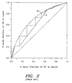
- the cycle shown in Fig. 1 is considered to be one of the most efficient cycles for the production of impure oxygen. Nonetheless, analysis of composition profiles in the low pressure column for this system demonstrate a significant region of process irreversibility. This region is graphically represented by the area between the operating line "O" and the equilibrium line "E” shown in Fig. 2. In a strongly competitive market, there is a demand to reduce this irreversibility and the power required by this cycle even further.
- the present invention is directed to a method for cryogenically distilling air using a system having a higher pressure column, a lower pressure column, and a medium pressure column to produce at least one of nitrogen and impure oxygen.
- the cycle includes a classic dual column system, along with a discrete medium pressure column having a pressure between the pressures of the higher pressure column and the lower pressure column.
- the present invention reduces irreversibilities of separation in the lower pressure column by delivering crude oxygen as a vapor to the lower pressure column.
- a portion of the feed air is introduced directly to the medium pressure column, which results in power savings as compared to cycles which require the entire stream of feed air to be pressurized to the higher pressure of the higher pressure column.
- a method of producing substantially pure nitrogen and impure oxygen by cryogenic distillation in a system having a higher pressure column, a lower pressure column, and a medium pressure column comprising the steps of:
- both a portion of the higher pressure nitrogen condensate and a portion of the medium pressure nitrogen condensate are introduced into the lower pressure column as reflux.
- the at least partial condensation of the higher pressure nitrogen overhead includes introducing at least a portion of the overhead into an intermediate reboiler/condenser of the lower pressure column; a third compressed and cooled feed air stream is condensed in a bottom reboiler/condenser of the lower pressure column to form liquefied feed air; and at least a portion of said liquefied feed air is fed to at least one of the higher pressure column, the medium pressure column, and the lower pressure column.
- a first portion of the liquefied feed air is introduced into the higher pressure column; a second portion of the liquefied feed air is introduced to the medium pressure column; and a third portion of the liquefied feed air is introduced into the lower pressure column.
- the oxygen-enriched product stream can be withdrawn as a liquid and pressurized to form a pressurized oxygen-enriched product stream; the pressurized stream vaporized against a condensing high pressure feed air stream at a pressure higher than the first pressure; and the condensed stream reduced in pressure and at least a portion thereof fed to at least one of the higher pressure column, the medium pressure column, and the lower pressure column.
- a first portion of the liquefied feed air is introduced into the higher pressure column; a second portion of the liquefied feed air is introduced to the medium pressure column; and a third portion of the liquefied feed air is introduced into the lower pressure column.
- the at least partial condensation of the higher pressure nitrogen overhead includes introducing at least a portion of the overhead into a bottom reboiler/condenser of the lower pressure column and the oxygen-enriched product stream is withdrawn as a liquid and introduced into a top reboiler/condenser of the lower pressure column to provide additional reflux to the column and to vaporize the oxygen-enriched product.
- the at least partial condensation of the higher pressure nitrogen overhead includes introducing a first portion of the overhead into a bottom reboiler/condenser of the lower pressure column and introducing a second portion of the overhead into a side reboiler/condenser of the lower pressure column; and the oxygen-enriched product stream is withdrawn as a liquid, reduced in pressure and vaporized in the side reboiler/condenser
- the reflux to the lower pressure column is subcooled by heat exchange against the nitrogen-enriched product stream
- the at least partial condensation of the medium pressure nitrogen overhead can include introducing the first reduced-pressure oxygen-enriched liquid into a top reboiler/ condenser of the medium pressure column to form the oxygen-enriched vapor stream and to condense the medium pressure nitrogen overhead.
- the pressure of the higher pressure, oxygen-enriched liquid (100) can be reduced to form an intermediate reduced-pressure oxygen-enriched liquid and combined with the medium pressure, oxygen-enriched liquid to form a combined oxygen-enriched liquid and the pressure of at least a portion of the combined oxygen-enriched liquid reduced to form the first reduced-pressure oxygen-enriched liquid.
- the pressure of a second portion of the combined oxygen-enriched liquid can be reduced to form a further reduced-pressure oxygen-enriched liquid which is introduced into the lower pressure column or the pressure of all of the combined oxygen-enriched liquid reduced to form the first reduced-pressure oxygen-enriched liquid.
- the higher pressure, oxygen-enriched liquid can be reduced in pressure and introduced into the medium pressure column.
- first, second and any further feed air streams will be provided from a single main air feed.
- the main air feed is first compressed to the second pressure to provide the second feed air stream and a portion of the compressed feed air is further compressed to provide the first feed air stream or the main air feed is first compressed to the first pressure to provide the first feed air stream and a portion of the compressed feed air expanded to provide the second feed air stream.
- the oxygen-enriched vapor can be formed by at least partially condensing the medium pressure nitrogen overhead against the first reduced-pressure, oxygen-enriched liquid separated into a first portion having a first oxygen concentration and a second portion having a higher second oxygen concentration; said first portion introduced into a first location of the lower pressure column; and said second portion introduced into a lower second location of the lower pressure column.
- the present invention also provides an apparatus for producing substantially pure nitrogen and impure oxygen by a method of the invention; said apparatus comprising:
- the present invention calls for feed air to be introduced to, for example, at least one compressor, at least one heat exchanger, and at least one expander to provide (a) a medium pressure feed air stream and (b) a higher pressure feed air stream.
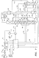
- a feed air stream in line 10 is compressed in compressor 12, cooled in heat exchanger 14, cleaned of water and carbon dioxide, preferably in molecular sieve adsorption unit 16, and divided into two streams: the medium pressure feed air stream in line 18 and stream in line 30.
- Medium pressure feed air stream in line 18 is cooled in a main heat exchanger 20 to a cryogenic temperature and introduced as feed in line 22 to the medium pressure column 24. There, the medium pressure feed air stream (along with another feed discussed below) is rectified into a medium pressure, oxygen-enriched liquid (withdrawn as a bottom product via line 110) and a medium pressure nitrogen overhead stream (withdrawn as an overhead vapor in line 105).
- Compressed feed air stream in line 30 is further compressed in compressor 32, cooled in heat exchanger 34 against an external cooling fluid, and split into two streams in lines 36 and 70.
- Stream in line 36 is cooled in main heat exchanger 20 close to its dew point and divided into two streams: a first fraction of the higher pressure feed air stream in line 38 and a second fraction of the higher pressure feed air stream in line 40.
- the first fraction of the higher pressure feed air stream in line 38 is introduced as a feed into the higher pressure column 60 for rectification (along with another feed discussed below) into a higher pressure, oxygen-enriched liquid (withdrawn as a bottom product via line 100) and a higher pressure nitrogen overhead stream 80.
- the second fraction of the higher pressure feed air stream in line 40 is condensed in a bottom reboiler/condenser 42, located in the bottom of the lower pressure column 62, thereby forming liquefied feed air in line 46 and providing a part of the reboil necessary for the separation in the lower pressure column 62.
- Liquefied feed air in line 46 may be divided into three streams: a first portion in line 48, a second portion in line 50, and a third portion in line 52, which form liquefied air feeds to higher pressure column 60, medium pressure column 24 and lower pressure column 62, respectively.
- liquefied feed air in line 46 may be directed to only one of higher pressure column 60, medium pressure column 24 or, preferably, lower pressure column 62, or any combination of any two of them.
- the operating pressures of the three columns can vary over wide ranges, such as 18-180 psia (125-1256 kPa) for lower pressure column 62, 35-250 psia (250-1750 kPa) for medium pressure column 24, and 55-350 psia (375-2400 kPa) for higher pressure column 60.
- the portion of the further compressed feed air stream in line 70 is compressed, then cooled and expanded and introduced as a lower pressure feed air stream to lower pressure column 62.
- the stream in line 70 is compressed in compander compressor 72, cooled in heat exchanger 74 against an external cooling fluid, cooled in main heat exchanger 20, and expanded in turbo-expander 76. Then, the stream is introduced via line 78 to lower pressure column 62 as a lower pressure feed air stream.
- the first fraction of the higher pressure feed air stream in line 38 and the first portion of the liquefied air feed in line 48 are introduced to higher pressure column 60, where they are rectified into the higher pressure, oxygen-enriched liquid withdrawn in line 100 and a higher pressure nitrogen overhead stream withdrawn in line 80.
- the higher pressure nitrogen overhead stream in line 80 is condensed against a liquid from lower pressure column 62 to form higher pressure nitrogen condensate in line 84, a portion of which is returned to higher pressure column 60 in line 86 as reflux.
- the higher pressure nitrogen overhead stream is condensed in an intermediate reboiler/condenser 82 located in lower pressure column 62 above bottom reboiler/condenser 42.
- a separate device disposed near and connected to lower pressure column 62 by appropriate vapor and liquid lines, may be utilized.
- the remaining portion of the higher pressure nitrogen condensate is withdrawn via line 88, subcooled in a heat exchanger 90, reduced in pressure across an isenthalpic Joule-Thompson valve 89 and flashed in a separator 92.
- the resulting low pressure nitrogen reflux is introduced via line 94 close to the top of lower pressure column 62.
- medium pressure feed air stream in line 22 and second portion of liquefied feed air in line 50 are introduced to medium pressure column 24, where they are rectified into a medium pressure, oxygen-enriched liquid (withdrawn via line 110 as a bottom product) and a medium pressure nitrogen overhead stream, which is condensed in a top reboiler/condenser 106 via line 105.
- a portion of the medium pressure nitrogen condensate provides reflux for medium pressure column 24, and the remaining portion in line 112 is subcooled in heat exchanger 90 and reduced in pressure across an isenthalpic Joule-Thompson valve 91.
- the stream is then flashed in separator 92 to provide additional reflux to lower pressure column 62 via line 94.
- At least a portion of at least one of the medium pressure, oxygen-enriched liquid and the higher pressure, oxygen-enriched liquid is reduced in pressure to form a first reduced-pressure, oxygen-enriched liquid, and the first reduced-pressure, oxygen-enriched liquid is used as the cooling medium to condense the medium pressure nitrogen overhead stream in the top reboiler/condenser 106 of medium pressure column 24.
- the first reduced-pressure, oxygen-enriched liquid is used as the cooling medium to condense the medium pressure nitrogen overhead stream in the top reboiler/condenser 106 of medium pressure column 24.
- the resulting vapor stream in line 108 is introduced to lower pressure column 62, as an oxygen-enriched vapor stream.
- Stream in line 102 is optional, and for some operating conditions not necessary (i.e., the flow in line 102 may be zero).
- the stream in line 102 is reduced in pressure across an isenthalpic Joule-Thompson valve 109 and introduced into lower pressure column 62.
- two product streams are withdrawn: (1) an oxygen-enriched product from a position near the bottom of the lower pressure column; and a nitrogen-enriched product from a position near the top of the lower pressure column.
- Either product may be withdrawn as a liquid or a gas depending on the particular needs, although nitrogen is preferably withdrawn as a gas.
- nitrogen is preferably withdrawn as a gas.
- gaseous nitrogen product in line 116 is withdrawn from the top of lower pressure column 62 in line 114, combined with any flash gases from separator 92, and warmed up in: (1) heat exchanger 90 against higher pressure nitrogen condensate in line 88 and medium pressure nitrogen condensate in line 112, (2) heat exchanger 103 against higher pressure, oxygen-enriched liquid in line 100, and (3) main heat exchanger 20 against medium pressure feed air stream in line 22 and higher pressure feed air stream in line 36 and the stream from compander compressor 72 and heat exchanger 74. Also in the embodiment shown in Fig.
- oxygen product 120 is recovered as a vapor from the bottom of lower pressure column 62 in line 118 and is warmed up in main heat exchanger 20 against medium pressure feed air stream in line 22 and higher pressure feed air stream in line 36 and the stream from compander compressor 72 and heat exchanger 74.
- FIG. 5-10 the embodiments shown in Fig. 5 and in Fig. 6 are directed to using the medium pressure column with a nitrogen generator. Such nitrogen plants also produce impure oxygen as a waste.
- the irreversibilities are greatly reduced by introduction of the third, medium pressure column, which allows crude oxygen to be supplied to the low pressure column in the form of vapor instead of liquid, as discussed above in connection with Fig. 3.
- the embodiment shown in Fig. 5 differs from that of Fig. 3 in that there is no intermediate reboiler/condenser but instead there is a top reboiler/condenser 130 of lower pressure column 62. Also, in the embodiment shown in Fig. 5, all of the further compressed feed air stream in line 36 is directed via line 38 to higher pressure column 60. In this embodiment, the step of condensing higher pressure nitrogen overhead stream in line 80 against a liquid from lower pressure column 62 includes introducing higher pressure nitrogen overhead stream in line 80 to a bottom reboiler/condenser 42 of lower pressure column 62.
- the oxygen-enriched stream is withdrawn as a liquid via line 132 from a position near the bottom of lower pressure column 62 and introduced to top reboiler/condenser 130 of lower pressure column 62 to provide additional reflux to lower pressure column 62 and to vaporize the oxygen-enriched stream, which could be classified as a product for some uses, but is typically a waste stream in this embodiment.
- This oxygen-enriched stream is warmed in heat exchangers 90 and 103, as well as in main heat exchanger 20.
- the embodiment shown in Fig. 6 differs from that of Fig. 3 in that there is no intermediate reboiler/condenser but instead there is a side reboiler/condenser 134 of lower pressure column 62. Also, as in the embodiment shown in Fig. 5, all of the further compressed feed air stream in line 36 is directed via line 38 to higher pressure column 60.
- the step of condensing higher pressure nitrogen overhead stream includes the steps of introducing a first portion of higher pressure nitrogen overhead stream to bottom reboiler/condenser 42 of lower pressure column 62 and introducing a second portion of higher pressure nitrogen overhead stream to side reboiler/condenser 134 of lower pressure column 62.
- Side reboiler/condenser 134 can be contained within the column of lower pressure column 62 or situated next to it. Furthermore, the step of withdrawing an oxygen-enriched product from a position near the bottom of lower pressure column 62 includes first withdrawing an oxygen-enriched product as a liquid from a position near the bottom of lower pressure column 62 via line 136. This stream is reduced in pressure across an isenthalpic Joule-Thompson valve 137 to form a reduced-pressure, oxygen-enriched product which is delivered to side reboiler 134 and used to condense the second portion of the higher pressure nitrogen overhead stream.
- FIG. 7 Another embodiment of the present invention is shown in Fig. 7.
- This cycle differs from the cycle presented in Fig. 3 in the manner in which the higher pressure, oxygen-enriched liquid in line 100 is used.
- the higher pressure, oxygen-enriched liquid stream in line 100 is reduced in pressure across valve 101 and introduced to the bottom of medium pressure column 24 where it is flashed, thus providing extra reboil for medium pressure column 24 and additional nitrogen reflux to the lower pressure column.
- the medium pressure, oxygen-enriched liquid in line 110 is cooled in heat exchanger 103, reduced in pressure in an isenthalpic Joule-Thompson valve 107 in line 104, then introduced to top reboiler/condenser 106 of medium pressure column 24.
- a portion of the medium pressure, oxygen-enriched liquid may be delivered to lower pressure column 62 via line 102.
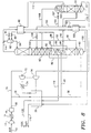
- Fig. 8 differs from the embodiment of Fig. 3 in that the entire feed air stream is compressed to a higher pressure to form the higher pressure feed air stream in line 30, then a portion of higher pressure feed air stream in line 70 is expanded in an expander 76 to form medium pressure feed air stream in line 22, as opposed to being delivered to lower pressure column 62.
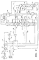
- the embodiment shown in Fig. 9 differs from the embodiment of Fig. 3 in that a small section of stages or packing 150 is added above top reboiler/condenser 106 of medium pressure column 24. With the inclusion of additional stages or packing 150, the reduced-pressure, oxygen-enriched liquid is partially separated as it is being vaporized. Specifically, it is separated into two portions: (1) a first portion having a first concentration which is withdrawn in line 152; and (2) a second portion having a second concentration, less pure in oxygen than the first concentration, which is withdrawn in line 108. Streams in line 152 and 108 are introduced to lower pressure column 62 at different locations. Specifically, stream in line 108 is introduced above the point at which stream in line 152 is introduced to lower pressure column 62. This embodiment further reduces the irreversibilities of separation in the lower pressure column resulting in additional power savings.
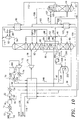
- the embodiment shown in Fig. 10 differs from the cycle of Fig. 3 by the manner in which oxygen product is withdrawn. Specifically, the embodiment shown in Fig. 10 is desirable if oxygen product is needed at a high pressure without the need to include an expensive oxygen compressor in the system.
- oxygen-enriched product is withdrawn as a liquid from the bottom of lower pressure column 62 via line 300. This stream may be pumped via pump 310 to the desired higher pressure. Alternatively, pump 310 may not be needed if a lower oxygen pressure is desired; specifically, several pounds (kPas) of oxygen product pressure can be obtained due to the static head gain caused by the height difference between the point at which liquid oxygen is withdrawn from the lower pressure column 62 and the point where it is boiled.
- Pressurized oxygen-enriched product in line 320 is then introduced to a heat exchanger 250, where it is vaporized and heated, exiting as stream in line 330. Stream in line 330 is further warmed in main heat exchanger 20.
- the medium directed to heat exchanger 250 which is used to heat the pressurized oxygen-enriched product from line 320, is a highest pressure feed air stream in line 240.
- Stream in line 240 is obtained by removing a portion of stream in line 70 via line 200, boosting this portion to a sufficient pressure in auxiliary compressor 210, and cooling the stream in heat exchanger 220 to form stream in line 230 which is cooled further in main heat exchanger 20.
- Stream in line 240 is condensed in heat exchanger 250 to form liquefied feed air 260 which is joined with liquid air stream 48 to form liquefied air stream 49, which is subsequently delivered to higher pressure column 60.
- liquid air stream 260 could be introduced also to streams in lines 46, 50, or 52.
- separate heat exchanger 250 may not be necessary as oxygen could be boiled in main heat exchanger 20 under certain conditions.
Landscapes
- Engineering & Computer Science (AREA)
- Physics & Mathematics (AREA)
- Mechanical Engineering (AREA)
- Thermal Sciences (AREA)
- General Engineering & Computer Science (AREA)
- Health & Medical Sciences (AREA)
- Emergency Medicine (AREA)
- Separation By Low-Temperature Treatments (AREA)
Applications Claiming Priority (2)
| Application Number | Priority Date | Filing Date | Title |
|---|---|---|---|
| US738158 | 1991-07-29 | ||
| US08/738,158 US5682764A (en) | 1996-10-25 | 1996-10-25 | Three column cryogenic cycle for the production of impure oxygen and pure nitrogen |
Publications (3)
| Publication Number | Publication Date |
|---|---|
| EP0838647A2 true EP0838647A2 (fr) | 1998-04-29 |
| EP0838647A3 EP0838647A3 (fr) | 1998-10-21 |
| EP0838647B1 EP0838647B1 (fr) | 2002-07-31 |
Family
ID=24966811
Family Applications (1)
| Application Number | Title | Priority Date | Filing Date |
|---|---|---|---|
| EP97308318A Expired - Lifetime EP0838647B1 (fr) | 1996-10-25 | 1997-10-20 | Production cryogénique à trois colonnes d'oxygène impur et d'azote pur |
Country Status (10)
| Country | Link |
|---|---|
| US (1) | US5682764A (fr) |
| EP (1) | EP0838647B1 (fr) |
| JP (1) | JPH10185425A (fr) |
| KR (1) | KR19980033136A (fr) |
| CA (1) | CA2218630A1 (fr) |
| DE (1) | DE69714377T2 (fr) |
| MX (1) | MX9708225A (fr) |
| NO (1) | NO974854L (fr) |
| SG (1) | SG49367A1 (fr) |
| TW (1) | TW341647B (fr) |
Cited By (1)
| Publication number | Priority date | Publication date | Assignee | Title |
|---|---|---|---|---|
| CN102985775A (zh) * | 2009-12-10 | 2013-03-20 | 普莱克斯技术有限公司 | 氧气产生方法和设备 |
Families Citing this family (21)
| Publication number | Priority date | Publication date | Assignee | Title |
|---|---|---|---|---|
| US5761927A (en) * | 1997-04-29 | 1998-06-09 | Air Products And Chemicals, Inc. | Process to produce nitrogen using a double column and three reboiler/condensers |
| US5901579A (en) * | 1998-04-03 | 1999-05-11 | Praxair Technology, Inc. | Cryogenic air separation system with integrated machine compression |
| US6116052A (en) * | 1999-04-09 | 2000-09-12 | Air Liquide Process And Construction | Cryogenic air separation process and installation |
| US6347534B1 (en) | 1999-05-25 | 2002-02-19 | Air Liquide Process And Construction | Cryogenic distillation system for air separation |
| US6196024B1 (en) | 1999-05-25 | 2001-03-06 | L'air Liquide, Societe Anonyme Pour L'etude Et L'exploitation Des Procedes Georges Claude | Cryogenic distillation system for air separation |
| US6276170B1 (en) | 1999-05-25 | 2001-08-21 | Air Liquide Process And Construction | Cryogenic distillation system for air separation |
| US6202441B1 (en) | 1999-05-25 | 2001-03-20 | Air Liquide Process And Construction, Inc. | Cryogenic distillation system for air separation |
| US6227005B1 (en) | 2000-03-01 | 2001-05-08 | Air Products And Chemicals, Inc. | Process for the production of oxygen and nitrogen |
| FR2814229B1 (fr) * | 2000-09-19 | 2002-10-25 | Air Liquide | Procede et installation de separation d'air par distillation cryogenique |
| DE10113790A1 (de) * | 2001-03-21 | 2002-09-26 | Linde Ag | Drei-Säulen-System zur Tieftemperatur-Luftzerlegung |
| US6536234B1 (en) | 2002-02-05 | 2003-03-25 | Praxair Technology, Inc. | Three column cryogenic air separation system with dual pressure air feeds |
| EP1815792B1 (fr) | 2004-10-25 | 2016-06-01 | ARKRAY, Inc. | Lancette et dispositif à lancette l'utilisant |
| US8640496B2 (en) * | 2008-08-21 | 2014-02-04 | Praxair Technology, Inc. | Method and apparatus for separating air |
| US20110138856A1 (en) * | 2009-12-10 | 2011-06-16 | Henry Edward Howard | Separation method and apparatus |
| FR2959802B1 (fr) * | 2010-05-10 | 2013-01-04 | Air Liquide | Procede et appareil de separation d'air par distillation cryogenique |
| EP2634517B1 (fr) * | 2012-02-29 | 2018-04-04 | L'Air Liquide Société Anonyme pour l'Etude et l'Exploitation des Procédés Georges Claude | Procédé et appareil pour la séparation d'air par distillation cryogénique |
| TW201518664A (zh) * | 2013-07-11 | 2015-05-16 | Linde Ag | 產生至少一空氣產品之方法,空氣分離設備,發電方法及發電裝置 |
| JP6092804B2 (ja) * | 2014-03-24 | 2017-03-08 | 大陽日酸株式会社 | 空気液化分離方法及び装置 |
| US10415760B2 (en) * | 2017-04-18 | 2019-09-17 | Air Products And Chemicals, Inc. | Control system in an industrial gas pipeline network to satisfy energy consumption constraints at production plants |
| US12385692B2 (en) * | 2022-10-18 | 2025-08-12 | Air Products And Chemicals, Inc. | Process and apparatus for improved recovery of argon |
| US20250290692A1 (en) | 2024-03-18 | 2025-09-18 | Air Products And Chemicals, Inc. | Apparatus and process for providing nitrogen and oxygen |
Family Cites Families (13)
| Publication number | Priority date | Publication date | Assignee | Title |
|---|---|---|---|---|
| US3210951A (en) * | 1960-08-25 | 1965-10-12 | Air Prod & Chem | Method for low temperature separation of gaseous mixtures |
| GB1182615A (en) * | 1967-06-01 | 1970-02-25 | Roman Stoklosinski | Improvements in or relating to the Separation of Mixtures of Gases |
| US4453957A (en) * | 1982-12-02 | 1984-06-12 | Union Carbide Corporation | Double column multiple condenser-reboiler high pressure nitrogen process |
| US4617036A (en) * | 1985-10-29 | 1986-10-14 | Air Products And Chemicals, Inc. | Tonnage nitrogen air separation with side reboiler condenser |
| US4702757A (en) * | 1986-08-20 | 1987-10-27 | Air Products And Chemicals, Inc. | Dual air pressure cycle to produce low purity oxygen |
| US5069699A (en) * | 1990-09-20 | 1991-12-03 | Air Products And Chemicals, Inc. | Triple distillation column nitrogen generator with plural reboiler/condensers |
| EP0636845B1 (fr) * | 1993-04-30 | 1999-07-28 | The BOC Group plc | Séparation d'air |
| US5341646A (en) * | 1993-07-15 | 1994-08-30 | Air Products And Chemicals, Inc. | Triple column distillation system for oxygen and pressurized nitrogen production |
| GB9325648D0 (en) * | 1993-12-15 | 1994-02-16 | Boc Group Plc | Air separation |
| GB9414939D0 (en) * | 1994-07-25 | 1994-09-14 | Boc Group Plc | Air separation |
| US5582032A (en) * | 1995-08-11 | 1996-12-10 | Liquid Air Engineering Corporation | Ultra-high purity oxygen production |
| DE19537913A1 (de) * | 1995-10-11 | 1997-04-17 | Linde Ag | Dreifachsäulenverfahren zur Tieftemperaturzerlegung von Luft |
| US5675977A (en) * | 1996-11-07 | 1997-10-14 | Praxair Technology, Inc. | Cryogenic rectification system with kettle liquid column |
-
1996
- 1996-10-25 US US08/738,158 patent/US5682764A/en not_active Expired - Fee Related
-
1997
- 1997-09-23 SG SG1997003509A patent/SG49367A1/en unknown
- 1997-10-20 EP EP97308318A patent/EP0838647B1/fr not_active Expired - Lifetime
- 1997-10-20 DE DE69714377T patent/DE69714377T2/de not_active Expired - Fee Related
- 1997-10-20 CA CA002218630A patent/CA2218630A1/fr not_active Abandoned
- 1997-10-21 TW TW086115559A patent/TW341647B/zh active
- 1997-10-21 NO NO974854A patent/NO974854L/no unknown
- 1997-10-24 KR KR1019970054723A patent/KR19980033136A/ko not_active Abandoned
- 1997-10-24 JP JP9292926A patent/JPH10185425A/ja active Pending
- 1997-10-24 MX MX9708225A patent/MX9708225A/es not_active Application Discontinuation
Cited By (2)
| Publication number | Priority date | Publication date | Assignee | Title |
|---|---|---|---|---|
| CN102985775A (zh) * | 2009-12-10 | 2013-03-20 | 普莱克斯技术有限公司 | 氧气产生方法和设备 |
| CN102985775B (zh) * | 2009-12-10 | 2015-08-19 | 普莱克斯技术有限公司 | 氧气产生方法和设备 |
Also Published As
| Publication number | Publication date |
|---|---|
| DE69714377D1 (de) | 2002-09-05 |
| MX9708225A (es) | 1998-04-30 |
| SG49367A1 (en) | 1998-05-18 |
| EP0838647A3 (fr) | 1998-10-21 |
| TW341647B (en) | 1998-10-01 |
| KR19980033136A (ko) | 1998-07-25 |
| US5682764A (en) | 1997-11-04 |
| NO974854D0 (no) | 1997-10-21 |
| DE69714377T2 (de) | 2003-03-06 |
| NO974854L (no) | 1998-04-27 |
| JPH10185425A (ja) | 1998-07-14 |
| EP0838647B1 (fr) | 2002-07-31 |
| CA2218630A1 (fr) | 1998-04-25 |
Similar Documents
| Publication | Publication Date | Title |
|---|---|---|
| EP0838647B1 (fr) | Production cryogénique à trois colonnes d'oxygène impur et d'azote pur | |
| EP0645595B1 (fr) | Schémas de séparation d'air pour la coproduction d'oxygène et d'azote comme produit gazeux et/ou liquide | |
| EP0464630B1 (fr) | Système de séparation cryogénique de l'air à vaporiseur auxiliaire pour les deux produits | |
| US4702757A (en) | Dual air pressure cycle to produce low purity oxygen | |
| CA2228799C (fr) | Separation de l'air avec etapes de vaporisation sous pression intermediaire et de detente | |
| AU680472B2 (en) | Single column process and apparatus for producing oxygen at above atmospheric pressure | |
| EP0153673A2 (fr) | Cycle de génération de l'azote à alimentation double de l'air sous pression | |
| US4783210A (en) | Air separation process with modified single distillation column nitrogen generator | |
| MXPA97008225A (en) | A cryogenic cycle of three columns for the production of impure oxygen and nitrogen p | |
| EP0646755B2 (fr) | Procédé et installation de séparation cryogénique d'air pour la production d'azote sous pression élevée à partir d'azote liquide pompée | |
| EP0577349A1 (fr) | Séparation d'air | |
| CA2232405C (fr) | Systeme de rectification cryogenique pour la production d'azote a haute pression et d'oxygene a haute pression | |
| EP0936429B1 (fr) | Système de rectification cryogénique pour la production d'azote d'ultra-haute pureté et d'oxygène d'ultra-haute pureté | |
| US5467602A (en) | Air boiling cryogenic rectification system for producing elevated pressure oxygen | |
| EP0823606B1 (fr) | Procédé de production d'azote en utilisant une double colonne et une zone auxiliare de séparation à basse pression | |
| US5628207A (en) | Cryogenic Rectification system for producing lower purity gaseous oxygen and high purity oxygen | |
| US20020053219A1 (en) | Method for plant and separating air by cryogenic distillation | |
| JP2000356465A (ja) | 空気分離用低温蒸留システム | |
| US6543253B1 (en) | Method for providing refrigeration to a cryogenic rectification plant | |
| US5386691A (en) | Cryogenic air separation system with kettle vapor bypass | |
| JP2000346546A (ja) | 空気分離用低温蒸留システム | |
| US4869742A (en) | Air separation process with waste recycle for nitrogen and oxygen production | |
| JP2002122380A (ja) | 空気を分離するための低温蒸留方法 | |
| US6460373B1 (en) | Cryogenic rectification system for producing high purity oxygen | |
| US6339938B1 (en) | Apparatus and process for separating air by cryogenic distillation |
Legal Events
| Date | Code | Title | Description |
|---|---|---|---|
| PUAI | Public reference made under article 153(3) epc to a published international application that has entered the european phase |
Free format text: ORIGINAL CODE: 0009012 |
|
| AK | Designated contracting states |
Kind code of ref document: A2 Designated state(s): DE ES FR GB IT NL |
|
| AX | Request for extension of the european patent |
Free format text: AL;LT;LV;RO;SI |
|
| PUAL | Search report despatched |
Free format text: ORIGINAL CODE: 0009013 |
|
| AK | Designated contracting states |
Kind code of ref document: A3 Designated state(s): AT BE CH DE DK ES FI FR GB GR IE IT LI LU MC NL PT SE |
|
| AX | Request for extension of the european patent |
Free format text: AL;LT;LV;RO;SI |
|
| 17P | Request for examination filed |
Effective date: 19990412 |
|
| AKX | Designation fees paid |
Free format text: DE ES FR GB IT NL |
|
| 17Q | First examination report despatched |
Effective date: 20000905 |
|
| GRAG | Despatch of communication of intention to grant |
Free format text: ORIGINAL CODE: EPIDOS AGRA |
|
| GRAG | Despatch of communication of intention to grant |
Free format text: ORIGINAL CODE: EPIDOS AGRA |
|
| GRAH | Despatch of communication of intention to grant a patent |
Free format text: ORIGINAL CODE: EPIDOS IGRA |
|
| GRAG | Despatch of communication of intention to grant |
Free format text: ORIGINAL CODE: EPIDOS AGRA |
|
| GRAH | Despatch of communication of intention to grant a patent |
Free format text: ORIGINAL CODE: EPIDOS IGRA |
|
| GRAH | Despatch of communication of intention to grant a patent |
Free format text: ORIGINAL CODE: EPIDOS IGRA |
|
| GRAA | (expected) grant |
Free format text: ORIGINAL CODE: 0009210 |
|
| AK | Designated contracting states |
Kind code of ref document: B1 Designated state(s): DE ES FR GB IT NL |
|
| PG25 | Lapsed in a contracting state [announced via postgrant information from national office to epo] |
Ref country code: NL Free format text: LAPSE BECAUSE OF FAILURE TO SUBMIT A TRANSLATION OF THE DESCRIPTION OR TO PAY THE FEE WITHIN THE PRESCRIBED TIME-LIMIT Effective date: 20020731 Ref country code: IT Free format text: LAPSE BECAUSE OF FAILURE TO SUBMIT A TRANSLATION OF THE DESCRIPTION OR TO PAY THE FEE WITHIN THE PRE;WARNING: LAPSES OF ITALIAN PATENTS WITH EFFECTIVE DATE BEFORE 2007 MAY HAVE OCCURRED AT ANY TIME BEFORE 2007. THE CORRECT EFFECTIVE DATE MAY BE DIFFERENT FROM THE ONE RECORDED.SCRIBED TIME-LIMIT Effective date: 20020731 |
|
| REG | Reference to a national code |
Ref country code: GB Ref legal event code: FG4D |
|
| REF | Corresponds to: |
Ref document number: 69714377 Country of ref document: DE Date of ref document: 20020905 |
|
| PGFP | Annual fee paid to national office [announced via postgrant information from national office to epo] |
Ref country code: GB Payment date: 20020913 Year of fee payment: 6 |
|
| PGFP | Annual fee paid to national office [announced via postgrant information from national office to epo] |
Ref country code: FR Payment date: 20021003 Year of fee payment: 6 |
|
| PGFP | Annual fee paid to national office [announced via postgrant information from national office to epo] |
Ref country code: DE Payment date: 20021031 Year of fee payment: 6 |
|
| ET | Fr: translation filed | ||
| NLV1 | Nl: lapsed or annulled due to failure to fulfill the requirements of art. 29p and 29m of the patents act | ||
| PG25 | Lapsed in a contracting state [announced via postgrant information from national office to epo] |
Ref country code: ES Free format text: LAPSE BECAUSE OF FAILURE TO SUBMIT A TRANSLATION OF THE DESCRIPTION OR TO PAY THE FEE WITHIN THE PRESCRIBED TIME-LIMIT Effective date: 20030130 |
|
| PLBE | No opposition filed within time limit |
Free format text: ORIGINAL CODE: 0009261 |
|
| STAA | Information on the status of an ep patent application or granted ep patent |
Free format text: STATUS: NO OPPOSITION FILED WITHIN TIME LIMIT |
|
| 26N | No opposition filed |
Effective date: 20030506 |
|
| PG25 | Lapsed in a contracting state [announced via postgrant information from national office to epo] |
Ref country code: GB Free format text: LAPSE BECAUSE OF NON-PAYMENT OF DUE FEES Effective date: 20031020 |
|
| PG25 | Lapsed in a contracting state [announced via postgrant information from national office to epo] |
Ref country code: DE Free format text: LAPSE BECAUSE OF NON-PAYMENT OF DUE FEES Effective date: 20040501 |
|
| GBPC | Gb: european patent ceased through non-payment of renewal fee |
Effective date: 20031020 |
|
| PG25 | Lapsed in a contracting state [announced via postgrant information from national office to epo] |
Ref country code: FR Free format text: LAPSE BECAUSE OF NON-PAYMENT OF DUE FEES Effective date: 20040630 |
|
| REG | Reference to a national code |
Ref country code: FR Ref legal event code: ST |