EP0838659B1 - Befestigungsvorrichtung für eine Krankenhausbettwaage - Google Patents
Befestigungsvorrichtung für eine Krankenhausbettwaage Download PDFInfo
- Publication number
- EP0838659B1 EP0838659B1 EP97308384A EP97308384A EP0838659B1 EP 0838659 B1 EP0838659 B1 EP 0838659B1 EP 97308384 A EP97308384 A EP 97308384A EP 97308384 A EP97308384 A EP 97308384A EP 0838659 B1 EP0838659 B1 EP 0838659B1
- Authority
- EP
- European Patent Office
- Prior art keywords
- mounting
- mounting block
- load cell
- support frame
- fastener
- Prior art date
- Legal status (The legal status is an assumption and is not a legal conclusion. Google has not performed a legal analysis and makes no representation as to the accuracy of the status listed.)
- Expired - Lifetime
Links
- 230000008878 coupling Effects 0.000 claims abstract description 8
- 238000010168 coupling process Methods 0.000 claims abstract description 8
- 238000005859 coupling reaction Methods 0.000 claims abstract description 8
- 238000009434 installation Methods 0.000 claims description 3
- 229910000831 Steel Inorganic materials 0.000 claims description 2
- 239000010959 steel Substances 0.000 claims description 2
- 230000001419 dependent effect Effects 0.000 claims 1
- 238000005303 weighing Methods 0.000 description 4
- 238000004519 manufacturing process Methods 0.000 description 2
- 238000005259 measurement Methods 0.000 description 2
- JOYRKODLDBILNP-UHFFFAOYSA-N Ethyl urethane Chemical compound CCOC(N)=O JOYRKODLDBILNP-UHFFFAOYSA-N 0.000 description 1
- HCHKCACWOHOZIP-UHFFFAOYSA-N Zinc Chemical compound [Zn] HCHKCACWOHOZIP-UHFFFAOYSA-N 0.000 description 1
- 239000013536 elastomeric material Substances 0.000 description 1
- 239000000463 material Substances 0.000 description 1
- 239000011701 zinc Substances 0.000 description 1
- 229910052725 zinc Inorganic materials 0.000 description 1
Images
Classifications
-
- G—PHYSICS
- G01—MEASURING; TESTING
- G01G—WEIGHING
- G01G19/00—Weighing apparatus or methods adapted for special purposes not provided for in the preceding groups
- G01G19/44—Weighing apparatus or methods adapted for special purposes not provided for in the preceding groups for weighing persons
- G01G19/445—Weighing apparatus or methods adapted for special purposes not provided for in the preceding groups for weighing persons in a horizontal position
-
- Y—GENERAL TAGGING OF NEW TECHNOLOGICAL DEVELOPMENTS; GENERAL TAGGING OF CROSS-SECTIONAL TECHNOLOGIES SPANNING OVER SEVERAL SECTIONS OF THE IPC; TECHNICAL SUBJECTS COVERED BY FORMER USPC CROSS-REFERENCE ART COLLECTIONS [XRACs] AND DIGESTS
- Y10—TECHNICAL SUBJECTS COVERED BY FORMER USPC
- Y10S—TECHNICAL SUBJECTS COVERED BY FORMER USPC CROSS-REFERENCE ART COLLECTIONS [XRACs] AND DIGESTS
- Y10S177/00—Weighing scales
- Y10S177/09—Scale bearings
Definitions
- the present invention relates to a hospital bed having the capability of weighing a patient located on the bed. More particularly, the present invention relates to an improved scale mounting apparatus for a hospital bed or other piece of equipment.
- the present invention relates to an improved scale mounting system for mounting a scale apparatus directly onto the bed to obtain a weight of the patient without moving the patient or the bed.
- the scale of the present invention is integrated with the frame system of the bed.
- Other such integrated scale devices are known. See, for example, U.S. Patents Nos. 4,953,244; 4,793,428; and 5,269,388.
- These known scales typically include load cells or linear variable differential transformers for measuring the weight of a patient on the bed.
- U.S. Patent No. 4,953,244 discloses a weigh frame coupled to a patient support surface.
- the weigh frame is mounted at its four corners by load cells to a bed support frame.
- the weight detected by the four load cells is summed and processed to provide a weight of the patient.
- EPA 0290880 discloses a load cell having an elastomeric mounting block.
- the present invention provides an improved scale mounting apparatus for securing a weigh frame to a support frame with load cells to each corner of the weigh frame.
- the present invention provides a scale mounting apparatus for coupling a fixed support frame to a movable weigh frame, the apparatus comprising a load cell having a first end rigidly coupled to the support frame and a second, movable end, a mounting bracket coupled to the weigh frame, a fastener for coupling the mounting bracket to the second, movable end of the load cell, characterised in that the apparatus further comprises an elastomeric mounting block.
- the fastener also coupling the mounting block to the second, movable end of the load cell; in that a washer is located between the fastener and the mounting block and in that the fastener extends through an aperture formed in each of the washer, the mounting block and the mounting bracket and into the second end of the load cell.
- the load cells used to measure the weight of the patient are sensitive to side loading. Such side loading can create weight errors.
- the mounting apparatus of the present invention provides a more stable mounting system which improves the linearity of the output from the load cells.
- the mounting apparatus of the present invention is easier to install, provides improved frame stability, increases accuracy and repeatability of the measurements from the load cells, and reduces costs of production and installation.
- the mounting block has a cylindrical shape.
- the mounting block has a hardness of about 70 to about 80 durometer.
- the washer includes an outer flange configured to extend over a lower portion of an outer surface of the mounting block.
- the illustrated mounting bracket is formed to include a recessed section for surrounding an upper portion of the outer surface of the mounting block.
- the fastener extends through a central aperture formed in each of the washer, the mounting block, the mounting bracket and into the second end of the load cell.
- the first end of the load cell is coupled to a bottom surface of the support frame, and the second, movable end of the load cell includes a mounting surface aligned generally parallel to the bottom surface of the support frame.
- the mounting surface includes a threaded aperture aligned with an opening formed in the bottom surface of the support frame.
- the threaded aperture is configured to receive a threaded end of the fastener to secure the mounting block and the mounting bracket to the load cell.
- a head of the fastener is located outside the support frame to facilitate installation of the scale mounting apparatus.
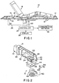
- FIG. 1 illustrates portions of a bed 10 such as a hospital bed.
- Bed 10 includes a stationary support frame 12 rigidly coupled to a base 13 of the bed 10.
- the base 13 is not shown in detail. It is understood that any type of conventional bed base 13 may be used in connection with the present invention.
- the bed 10 further includes a weigh frame 14 which is coupled to the support frame 12. Each corner of the weigh frame 14 is mounted to the support frame 12 by a separate scale mounting apparatus 16 in accordance with the present invention. Scale mounting apparatus 16 is described in detail below with reference to Figs. 2-4.
- An articulating deck 18 is mounted to the weigh frame 14 in a conventional manner.
- the articulating deck 18 provides a support surface for a patient on the bed 10. It is understood that any type of deck and support surface may be used to support the patient within the scope of the present invention.
- Each mounting apparatus 16 is coupled to a load cell 20 within support frame 12 as discussed below.
- Load cells 20 each provide an output signal indicating the weight applied to each load cell 20.
- Each load cell 20 is coupled to an input 22 of a controller 24 by a supply line 26. For clarity, only one such supply line 26 is illustrated in Fig. 1.
- the output signals from load cells 20 are processed in a conventional manner to provide an indication of the weight of the patient. See, for example, U.S. Patent No. 4,953,244.
- the controller 24 is coupled to a display 28 to provide an indication of the weight of the patient. Controller 24 may also be coupled to a communication network 30 to transmit data to another room or nurse station of the building or to a remote location.
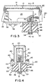
- Support frame 12 is formed to include a bottom surface 32 which is rigidly coupled to a first, fixed end 34 of load cell 20.
- Surface 32 of support frame 12 is formed to include an opening 36 adjacent the second movable end 38 of load cell 20.
- Weigh frame 14 is illustratively a U-shaped channel having opposite, parallel side walls 40. The U-shaped weigh frame 14 is configured to nest over the support frame 12 as best illustrated in Fig. 4.
- Mounting flanges 42 are formed integrally with weigh frame 14.
- a mounting bracket 44 is configured to be coupled to mounting flanges 42 of weigh frame 18 by suitable fasteners 46 illustrated in Fig. 4.
- An elastomeric mounting block 48 and a cup washer 50 are secured to the second, movable end 38 of load cell 20 by a suitable fastener 52.
- Movable portion 38 of load cell 20 includes a bottom surface 39 formed to include a threaded aperture 41 for receiving the fastener 52.
- Surface 39 is generally parallel to the bottom surface 32 of support frame 12.
- fastener 52 is a self locking shoulder screw which threads into a threaded aperture 41 formed in the movable end 38 of load cell 20 as best illustrated in Figs. 3 and 4.
- Threaded aperture 41 is aligned with the opening 36 formed in the bottom surface 32 of support frame 12 so that the threaded aperture is accessible from outside the support frame 12.
- a shaft 53 of fastener 52 extends upwardly through the cup washer 50, the mounting block 48, the mounting bracket 44, through opening 36 of support frame 12, and into the threaded second end 38 of load cell 20.
- a head 54 of fastener 52 engages the cup washer 50.
- Mounting bracket 44, mounting block 48, and cup washer 50 each include a central aperture 45, 49, and 51, respectively, for receiving the shaft 53 of fastener 52.
- the first, fixed end 34 of load cell 20 is secured to bottom surface 32 of support frame 12 by a mounting plate 56 and suitable fasteners 58 which extend upwardly into threaded apertures formed in the fixed end 34 of load cell 20. Therefore, the fixed end 34 of load cell 20 is rigidly secured to the bottom surface 32 of support frame 12.
- the weigh frame 18 is movable downwardly in the direction of arrow 60 when a patient is located on deck 18.
- mounting block 48 is a cylindrically shaped mounting block.
- Mounting block 48 is made from a elastomeric material such as urethane.
- mounting block 48 has a hardness of about 70 to about 80 durometer.
- Mounting bracket 44 is formed to include a recessed section defined by a wall 62 for surrounding an outer surface 64 of mounting block 48.
- Bottom support washer 50 also includes a flange 66 configured to extend over a portion of the outer surface 64 of mounting block 48. Therefore, mounting bracket 44 and washer 50 cooperate with fastener 52 to hold the mounting block in position. This provides improved stability for the weigh frame 14 and deck 18.
- washer 50 is a zinc-plated steel washer.
- mounting bracket 44 is made from a zinc diecast material.
- the improved scale mounting apparatus 16 of the present invention improves side-to-side stability for the weigh frame 14 and deck 18 mounted on the support frame 12. This provides a more stable platform for supporting the patient and reduces side loading on the load cells 20.
- the elastomeric mounting block 48 damps or reduces movement ofthe weigh frame 14 relative to the support frame 12.
- the elastomeric mounting block 48 is resilient enough to permit slight arcuate movement ofthe movable end 38 of load cell 20 so that the load cell 20 can operate in a conventional manner.
- each load cell 20 is a model no. MED400-10100 available from HBM located in Marlboro, Massachusetts.
- a separate scale mounting apparatus 16 is coupled to each corner of the weigh frame 14 as illustrated in Fig. 1.
- the load cells 20 are provided with conventional strain gauges which are connected to controller inputs 22 by supply lines 26.
- weigh frame 14 is moved downwardly in the direction of arrows 60 in Figs. 3 and 4. This applies a downwardly directed force in the direction of arrow 60 through the mounting bracket 44, through mounting block 48, through washer 50 and to the head 54 offastener 52. Therefore, the movable end 38 of load cell 20 is also deflected downwardly in the direction of arrows 60. This causes an output signal from the load cell 20 to change and indicate the weight on deck 18.
- the improved scale mounting apparatus 16 includes fastener 52 which threads directly into the movable end 38 of load cells 20 from a location outside of the support frame 12, the mounting apparatus 16 is easier to assemble and install than the mounting apparatus disclosed in U.S. Patent No. 4,953,244. An operator can simply line up the threaded aperture 41 formed in the bottom surface 39 of the load cell 20 with the aperture 45 in mounting bracket and then install the fastener 52 with the mounting block 48 and washer 50 as discussed above.
- the elastomeric mounting block 48 eliminates the need for a separate stop coupled to the load cell 20.
- the scale mounting apparatus 16 is easier to install, provides improved frame stability, and increases accuracy and repeatability of the measurements from the load cells 20. Production and assembly costs are also reduced.
Landscapes
- Physics & Mathematics (AREA)
- General Physics & Mathematics (AREA)
- Invalid Beds And Related Equipment (AREA)
- Magnetic Resonance Imaging Apparatus (AREA)
- Handcart (AREA)
Claims (13)
- Befestigungsapparat (16) für eine Wiegevorrichtung zum Verbinden eines ortsfesten Unterstützungsrahmens (12) mit einem beweglichen Wiegerahmen (14), wobei der Apparat eine Wiegezelle (20), welche ein erstes Ende (34), das starr mit dem Unterstützungsrahmen (12) verbunden ist, und ein zweites, bewegliches Ende (38) aufweist, einen Befestigungsbügel (44), der mit dem Wiegerahmen (14) verbunden ist, ein Befestigungselement (52) zum Verbinden des Befestigungsbügels (44) mit einem zweiten, beweglichen Ende (38) der Wiegezelle, umfasst, dadurch gekennzeichnet, dass der Apparat weiter einen elastomeren Befestigungsblock (48) umfasst, wobei das Befestigungselement (52) ebenfalls den Befestigungsblock (48) mit dem zweiten, beweglichen Ende (38) der Wiegezelle verbindet; dadurch, dass eine Scheibe (50) zwischen dem Befestigungselement (52) und dem Befestigungsblock (48) angeordnet ist, und dadurch, dass das Befestigungselement (52) sich durch eine Öffnung, weiche jeweils in der Scheibe (50), dem Befestigungsblock (48) und dem Befestigungsbügel (44) ausgeformt ist, und in das zweite Ende (38) der Wiegezelle erstreckt.
- Apparat gemäß Anspruch 1, wobei der Befestigungsblock (48) eine zylindrische Form aufweist.
- Apparat gemäß Anspruch 1 oder Anspruch 2, wobei der Befestigungsblock (48) eine Härte von ungefähr 70 bis ungefähr 80 Dorumeter aufweist.
- Apparat gemäß irgendeinem der vorangehenden Ansprüche, wobei das Befestigungselement (52) einen Kopf (54) umfasst, der mit der Scheibe (50) in Eingriff ist.
- Apparat gemäß irgendeinem der vorangehenden Ansprüche, wobei die Scheibe (50) aus Stahl gefertigt ist.
- Apparat gemäß irgendeinem der vorangehenden Ansprüche, wobei jeweils die Scheibe (50), der Befestigungsblock (48) sowie der Befestigungsbügel (44) unterhalb des zweiten Endes (38) der Wiegezelle positioniert sind.
- Apparat gemäß irgendeinem der vorangehenden Ansprüche, wobei die Scheibe (50) einen äußeren Flansch (66) einschließt, der so gestaltet ist, dass er sich über einen Anteil einer äußeren Fläche (64) des Befestigungsblockes (48) erstreckt.
- Apparat gemäß Anspruch 7, wobei der äußere Flansch (66) der Scheibe so gestaltet ist, dass er sich über einen unteren Anteil der äußeren Fläche (64) des Befestigungsblockes (48) erstreckt.
- Apparat gemäß irgendeinem der vorangehenden Ansprüche, wobei der Befestigungsbügel (44) so ausgeformt ist, dass er einen eingelassenen Abschnitt zum Umgeben eines Anteils einer äußeren Fläche (64) des Befestigungsblockes (48) einschließt.
- Apparat gemäß Anspruch 9 als Unteranspruch von Anspruch 8, wobei der eingelassene Abschnitt von einer Lippe (62) definiert wird, welche einen oberen Anteil der äußeren Fläche des Befestigungsblockes umgibt.
- Apparat gemäß irgendeinem der vorangehenden Ansprüche, wobei das erste Ende (34) der Wiegezelle mit einer Bodenfläche (32) des Unterstützungsrahmens (12) und das zweite, bewegliche Ende (38) der Wiegezelle eine Befestigungsfläche (39) einschließt, die im Allgemeinen parallel zu der Bodenfläche (32) des Unterstützungsrahmens ausgerichtet ist, wobei die Befestigungsfläche (39) eine mit Gewinde versehene Öffnung (41) einschließt, welche für die Aufnahme eines Gewindeendes des Befestigungselementes gestaltet ist, um den Befestigungsblock (48) sowie den Befestigungsbügel (44) mit der Wiegezelle (20) zu verbinden.
- Apparat gemäß Anspruch 11, wobei die mit Gewinde versehene Öffnung (41) mit einer Öffnung (36), welche in der Bodenfläche des Unterstützungsrahmens (12) ausformt ist, ausgerichtet ist.
- Apparat gemäß irgendeinem der vorangehenden Ansprüche, wobei ein Kopf (54) des Befestigungselementes (52) außerhalb des Unterstützungsrahmens (12) angeordnet ist, um die Anbringung des Befestigungsapparats für eine Wiegevorrichtung zu erleichtern.
Applications Claiming Priority (2)
| Application Number | Priority Date | Filing Date | Title |
|---|---|---|---|
| US735734 | 1985-05-20 | ||
| US08/735,734 US5859390A (en) | 1996-10-23 | 1996-10-23 | Hospital bed scale mounting apparatus |
Publications (3)
| Publication Number | Publication Date |
|---|---|
| EP0838659A2 EP0838659A2 (de) | 1998-04-29 |
| EP0838659A3 EP0838659A3 (de) | 1998-12-16 |
| EP0838659B1 true EP0838659B1 (de) | 2004-08-11 |
Family
ID=24956969
Family Applications (1)
| Application Number | Title | Priority Date | Filing Date |
|---|---|---|---|
| EP97308384A Expired - Lifetime EP0838659B1 (de) | 1996-10-23 | 1997-10-22 | Befestigungsvorrichtung für eine Krankenhausbettwaage |
Country Status (4)
| Country | Link |
|---|---|
| US (1) | US5859390A (de) |
| EP (1) | EP0838659B1 (de) |
| AT (1) | ATE273504T1 (de) |
| DE (1) | DE69730187T2 (de) |
Cited By (1)
| Publication number | Priority date | Publication date | Assignee | Title |
|---|---|---|---|---|
| CN101282686B (zh) * | 2005-10-11 | 2012-07-04 | 皇家飞利浦电子股份有限公司 | 用于监测床上的病人多个不同参数的系统 |
Families Citing this family (41)
| Publication number | Priority date | Publication date | Assignee | Title |
|---|---|---|---|---|
| KR20000028718A (ko) * | 1998-10-22 | 2000-05-25 | 가이자끼 요이찌로 | 하중측정장치 |
| US7834768B2 (en) * | 1999-03-05 | 2010-11-16 | Hill-Rom Services, Inc. | Obstruction detection apparatus for a bed |
| US6236001B1 (en) * | 1999-08-03 | 2001-05-22 | Wayne W. Shymko | Scoop with weigh scale |
| ATE447164T1 (de) * | 1999-09-29 | 2009-11-15 | Hill Rom Services Inc | Wägezellengerät |
| US6924441B1 (en) * | 1999-09-29 | 2005-08-02 | Hill-Rom Services, Inc. | Load cell apparatus |
| JP2003528307A (ja) * | 2000-03-20 | 2003-09-24 | ヒル−ロム サービシズ,インコーポレイテッド | 患者計量用装置 |
| US6362439B1 (en) * | 2000-04-21 | 2002-03-26 | Stress-Tek, Inc. | Load-cell mounting assembly |
| GB0015931D0 (en) * | 2000-06-30 | 2000-08-23 | Ferno Uk Limited | Improvements in or relating to patient handling apparatus |
| US6555767B1 (en) * | 2000-08-22 | 2003-04-29 | Flintec, Inc. | Composite load cell |
| US20050090721A1 (en) * | 2001-03-19 | 2005-04-28 | Shahzad Pirzada | Weighing and pump system for a bed |
| US6806430B2 (en) * | 2001-04-23 | 2004-10-19 | Ez Way, Inc. | Patient lift and scale |
| CA2448166A1 (en) | 2001-06-22 | 2003-01-03 | Hill-Rom Services, Inc. | Load cell apparatus having gap measuring device |
| EP1421458B1 (de) | 2001-08-03 | 2010-04-07 | Hill-Rom Services, Inc. | Patienten-point-of-care-computersystem |
| DE10308803A1 (de) * | 2002-03-15 | 2003-10-02 | Soehnle Waagen Gmbh & Co Kg | Waage |
| WO2005059486A1 (en) * | 2003-12-12 | 2005-06-30 | Hill-Rom Services, Inc. | Seat force sensor |
| US7112749B2 (en) * | 2004-06-23 | 2006-09-26 | Sensata Technologies, Inc. | Sensor mounting apparatus for minimizing parasitic stress |
| US7253366B2 (en) * | 2004-08-09 | 2007-08-07 | Hill-Rom Services, Inc. | Exit alarm for a hospital bed triggered by individual load cell weight readings exceeding a predetermined threshold |
| US7176391B2 (en) * | 2004-09-13 | 2007-02-13 | Hill-Rom Services, Inc. | Load cell to frame interface for hospital bed |
| EP1893822A4 (de) | 2005-06-10 | 2013-07-03 | Hill Rom Services Inc | Steuerung für druckbeaufschlagte blase in einer patientenstützvorrichtung |
| US8015972B2 (en) | 2006-01-03 | 2011-09-13 | Shahzad Pirzada | System, device and process for remotely controlling a medical device |
| US7849545B2 (en) * | 2006-11-14 | 2010-12-14 | Hill-Rom Industries Sa | Control system for hospital bed mattress |
| CZ18426U1 (cs) * | 2008-02-15 | 2008-04-07 | Linet, Spol. S R.O. | Polohovací mechanizmus lužka |
| DE102008011142B4 (de) * | 2008-02-26 | 2022-09-08 | Dr. Ing. H.C. F. Porsche Aktiengesellschaft | Überwachungssystem |
| KR101430196B1 (ko) * | 2008-08-18 | 2014-08-18 | 현대모비스 주식회사 | 승객식별장치 |
| US8717181B2 (en) | 2010-07-29 | 2014-05-06 | Hill-Rom Services, Inc. | Bed exit alert silence with automatic re-enable |
| US20120047655A1 (en) | 2010-08-26 | 2012-03-01 | O'keefe Christopher R | Incline based bed height |
| BE1019463A4 (nl) * | 2010-09-01 | 2012-07-03 | Vliet Ronny Van De | Weegmodule met geïntegreerde horizontale en verticale begrenzing. |
| US9492341B2 (en) | 2010-10-08 | 2016-11-15 | Hill-Rom Services, Inc. | Hospital bed with graphical user interface having advanced functionality |
| US10292605B2 (en) | 2012-11-15 | 2019-05-21 | Hill-Rom Services, Inc. | Bed load cell based physiological sensing systems and methods |
| US20150157520A1 (en) * | 2013-12-05 | 2015-06-11 | Stryker Corporation | Patient support |
| EP2995242B1 (de) | 2014-09-11 | 2023-11-15 | Hill-Rom S.A.S. | Patientenliegevorrichtung |
| US10045715B2 (en) | 2015-04-27 | 2018-08-14 | Hill-Rom Services, Inc. | Self-compensating bed scale system for removable components |
| US10054479B2 (en) | 2015-05-05 | 2018-08-21 | Hill-Rom Services, Inc. | Bed with automatic weight offset detection and modification |
| BR102015031525B1 (pt) * | 2015-12-16 | 2021-11-03 | Robert Bosch Limitada | Conjunto de barra de pesagem |
| JP6867891B2 (ja) * | 2017-06-16 | 2021-05-12 | ミネベアミツミ株式会社 | 荷重検出器、荷重検出システム、及び生体状態モニタリングシステム |
| US10969267B1 (en) * | 2019-03-01 | 2021-04-06 | Amazon Technologies, Inc. | Parallel planar weight sensing device |
| US11491062B2 (en) | 2019-04-18 | 2022-11-08 | Stryker Corporation | Patient handling apparatus with load sensor |
| US12527524B2 (en) | 2020-03-30 | 2026-01-20 | Hill-Rom Services, Inc. | Bed-based ballistocardiogram apparatus and method |
| SE544251C2 (en) | 2020-07-06 | 2022-03-15 | Arjo Ip Holding Ab | Patient handling apparatus comprising a weighing arrangement |
| CN113551756B (zh) * | 2021-06-04 | 2023-09-19 | 中国人民解放军陆军军医大学第二附属医院 | 一种医用体重秤 |
| US12564527B2 (en) | 2022-03-07 | 2026-03-03 | Hill-Rom Services, Inc. | Patient support apparatus having motorized wheels |
Family Cites Families (38)
| Publication number | Priority date | Publication date | Assignee | Title |
|---|---|---|---|---|
| US2990899A (en) * | 1958-11-24 | 1961-07-04 | Bella Isabelle D De | Bed patient weighing means |
| US3217818A (en) * | 1964-04-06 | 1965-11-16 | Harvey J Engelsher | Pneumatic weighing device |
| US3360062A (en) * | 1964-12-14 | 1967-12-26 | James A Potter | Scale for measuring change of weight of clinical patient |
| US3338323A (en) * | 1965-01-12 | 1967-08-29 | Francis Roe C | Hydraulic weighing apparatus with rebalancing means for determining load differential |
| US3512595A (en) * | 1967-09-27 | 1970-05-19 | Blh Electronics | Suspension-type strain gage transducer structure |
| FI47840C (fi) * | 1970-02-05 | 1974-04-10 | Datex Oy | Potilasvaaka |
| SE354851B (de) * | 1970-02-18 | 1973-03-26 | Haessle Ab | |
| US3656478A (en) * | 1970-04-13 | 1972-04-18 | Brookline Instr Co | Infusion monitor utilizing weight detecting means |
| US3876018A (en) * | 1972-01-03 | 1975-04-08 | Said Mracek By Said Bauer | Portable support for a bed patient |
| US3795284A (en) * | 1972-01-03 | 1974-03-05 | M Mracek | Portable support and weigher for a bed patient |
| US3773124A (en) * | 1972-08-16 | 1973-11-20 | Tron Corp K | Electronic weight transmitter |
| US3961675A (en) * | 1975-05-01 | 1976-06-08 | Vernon Harold Siegel | Portable housing for weighing systems |
| US4015677A (en) * | 1975-07-25 | 1977-04-05 | The United States Of America As Represented By The Secretary Of The Navy | Automatic patient weighing system |
| US4023633A (en) * | 1975-12-22 | 1977-05-17 | Swersey Burt L | Flexure scale |
| US4006789A (en) * | 1976-01-21 | 1977-02-08 | Acme Scale Company | Scale for weighing hospital patients in their horizontal position |
| US4033420A (en) * | 1976-05-20 | 1977-07-05 | Brookline Instrument Company, Inc. | Weighing scale |
| US4281730A (en) * | 1980-01-15 | 1981-08-04 | Swersey Burt L | Scale |
| US4363368A (en) * | 1981-03-13 | 1982-12-14 | Health Care Innovations, Inc. | Medical patient weighing scale |
| CA1205496A (en) * | 1981-05-04 | 1986-06-03 | Burt L. Swersey | Scale of flat construction for bedridden patient |
| US4550793A (en) * | 1981-05-13 | 1985-11-05 | Precision Engineering Products Limited (Suffolk) | Method and apparatus for checking the weight of a moving article |
| US4411327A (en) * | 1981-05-14 | 1983-10-25 | Hottinger Baldwin Measurements, Inc. | Apparatus for applying a load to a strain gage transducer beam |
| US4492281A (en) * | 1982-03-01 | 1985-01-08 | Scans Associates, Inc. | Weigh scale |
| US4438823A (en) * | 1982-08-09 | 1984-03-27 | Dbi Industries, Inc. | Load cell |
| US4539560A (en) * | 1982-12-10 | 1985-09-03 | Hill-Rom Company, Inc. | Bed departure detection system |
| US4487276A (en) * | 1983-05-03 | 1984-12-11 | Swersey Burt L | Scale of flat construction |
| US4629015A (en) * | 1984-11-28 | 1986-12-16 | Cobe Asdt, Inc. | Weight monitoring system |
| US4601356A (en) * | 1985-02-01 | 1986-07-22 | Muccillo Jr Vincent J | Suspended platform scale structure |
| US4751754A (en) * | 1987-04-02 | 1988-06-21 | Hill-Rom Company, Inc. | Dual hydraulic hospital bed with emergency bypass circuit |
| DE3715572A1 (de) * | 1987-05-09 | 1988-11-24 | Bizerba Werke Kraut Kg Wilh | Elektromechanische waage |
| US4765423A (en) * | 1987-11-05 | 1988-08-23 | Karpa Michael J | Load cell adaptor |
| US4953244A (en) * | 1987-12-28 | 1990-09-04 | Hill-Rom Company, Inc. | Hospital bed for weighing patients |
| US4934468A (en) * | 1987-12-28 | 1990-06-19 | Hill-Rom Company, Inc. | Hospital bed for weighing patients |
| US4793428A (en) * | 1988-02-29 | 1988-12-27 | Cobe Asdt, Inc. | Hospital bed with an integrated scale |
| US4961470A (en) * | 1989-05-25 | 1990-10-09 | Hill-Rom Company, Inc. | Weigh bed having vertical load link |
| US4899840A (en) * | 1989-06-22 | 1990-02-13 | Boubille Jacques C | Apparatus for weighing a pallet with a load thereon for use with a vehicle having tines or the like |
| US5173977A (en) * | 1991-10-04 | 1992-12-29 | Hill-Rom Company, Inc. | Load cell mount for hospital weigh bed |
| US5269388A (en) * | 1991-11-12 | 1993-12-14 | Stress-Tek, Inc. | Weighing bed |
| US5600104A (en) * | 1993-10-20 | 1997-02-04 | Structural Instrumentation, Inc. | Load cell having reduced sensitivity to non-symmetrical beam loading |
-
1996
- 1996-10-23 US US08/735,734 patent/US5859390A/en not_active Expired - Fee Related
-
1997
- 1997-10-22 DE DE69730187T patent/DE69730187T2/de not_active Expired - Fee Related
- 1997-10-22 EP EP97308384A patent/EP0838659B1/de not_active Expired - Lifetime
- 1997-10-22 AT AT97308384T patent/ATE273504T1/de not_active IP Right Cessation
Cited By (1)
| Publication number | Priority date | Publication date | Assignee | Title |
|---|---|---|---|---|
| CN101282686B (zh) * | 2005-10-11 | 2012-07-04 | 皇家飞利浦电子股份有限公司 | 用于监测床上的病人多个不同参数的系统 |
Also Published As
| Publication number | Publication date |
|---|---|
| EP0838659A3 (de) | 1998-12-16 |
| DE69730187D1 (de) | 2004-09-16 |
| ATE273504T1 (de) | 2004-08-15 |
| EP0838659A2 (de) | 1998-04-29 |
| US5859390A (en) | 1999-01-12 |
| DE69730187T2 (de) | 2004-12-30 |
Similar Documents
| Publication | Publication Date | Title |
|---|---|---|
| US5859390A (en) | Hospital bed scale mounting apparatus | |
| US5823278A (en) | Caster mounted weighing system | |
| US5831221A (en) | Caster mounted weighing system | |
| US4881606A (en) | Point-of-sale apparatus | |
| US6603081B2 (en) | Balance with a weighing compartment | |
| US5393938A (en) | In-bed patient scale | |
| JPH02291926A (ja) | データ収集システムの収容装着装置 | |
| CN100395523C (zh) | 力传感器的安装装置以及称量秤 | |
| EP1216400B1 (de) | Wägezellengerät | |
| US20050103535A1 (en) | Multipoint scale | |
| EP1423666B1 (de) | Waage mit niveaukompensationsfussbaugruppe | |
| US20020100621A1 (en) | Load-cell mounting assembly | |
| US7022921B2 (en) | Electronic scale assembly having incorporated spreader arm | |
| WO2003001162A1 (en) | Load cell apparatus having gap measuring device | |
| US20020046886A1 (en) | Apparatus and method for weighing the occupant of a bed | |
| CA2129438A1 (en) | Idler station arrangement for a scale apparatus | |
| US5881533A (en) | Process for adjusting machines | |
| EP0744598B1 (de) | Wägeeinrichtung | |
| US6053033A (en) | Device for determining the position of the center of gravity of a test body | |
| US20040124017A1 (en) | Apparatus and method for weighing the occupant of a bed | |
| US20060065450A1 (en) | Weighing scale with level compensating foot assembly | |
| WO2001020286A1 (en) | Web tension transducer apparatus | |
| EP0452957B1 (de) | Lastaufnehmeranordnung | |
| EP0534641A2 (de) | Unterbau für Wiegeplatte mit optischem Abtaster | |
| US4561511A (en) | Torsion load cell |
Legal Events
| Date | Code | Title | Description |
|---|---|---|---|
| PUAI | Public reference made under article 153(3) epc to a published international application that has entered the european phase |
Free format text: ORIGINAL CODE: 0009012 |
|
| AK | Designated contracting states |
Kind code of ref document: A2 Designated state(s): AT CH DE FR GB IT LI NL |
|
| PUAL | Search report despatched |
Free format text: ORIGINAL CODE: 0009013 |
|
| AK | Designated contracting states |
Kind code of ref document: A3 Designated state(s): AT BE CH DE DK ES FI FR GB GR IE IT LI LU MC NL PT SE |
|
| 17P | Request for examination filed |
Effective date: 19990614 |
|
| AKX | Designation fees paid |
Free format text: AT CH DE FR GB IT LI NL |
|
| 17Q | First examination report despatched |
Effective date: 20021113 |
|
| GRAP | Despatch of communication of intention to grant a patent |
Free format text: ORIGINAL CODE: EPIDOSNIGR1 |
|
| GRAS | Grant fee paid |
Free format text: ORIGINAL CODE: EPIDOSNIGR3 |
|
| RAP1 | Party data changed (applicant data changed or rights of an application transferred) |
Owner name: HILL-ROM SERVICES, INC. |
|
| GRAA | (expected) grant |
Free format text: ORIGINAL CODE: 0009210 |
|
| AK | Designated contracting states |
Kind code of ref document: B1 Designated state(s): AT CH DE FR GB IT LI NL |
|
| PG25 | Lapsed in a contracting state [announced via postgrant information from national office to epo] |
Ref country code: NL Free format text: LAPSE BECAUSE OF FAILURE TO SUBMIT A TRANSLATION OF THE DESCRIPTION OR TO PAY THE FEE WITHIN THE PRESCRIBED TIME-LIMIT Effective date: 20040811 Ref country code: LI Free format text: LAPSE BECAUSE OF FAILURE TO SUBMIT A TRANSLATION OF THE DESCRIPTION OR TO PAY THE FEE WITHIN THE PRESCRIBED TIME-LIMIT Effective date: 20040811 Ref country code: IT Free format text: LAPSE BECAUSE OF FAILURE TO SUBMIT A TRANSLATION OF THE DESCRIPTION OR TO PAY THE FEE WITHIN THE PRESCRIBED TIME-LIMIT;WARNING: LAPSES OF ITALIAN PATENTS WITH EFFECTIVE DATE BEFORE 2007 MAY HAVE OCCURRED AT ANY TIME BEFORE 2007. THE CORRECT EFFECTIVE DATE MAY BE DIFFERENT FROM THE ONE RECORDED. Effective date: 20040811 Ref country code: CH Free format text: LAPSE BECAUSE OF FAILURE TO SUBMIT A TRANSLATION OF THE DESCRIPTION OR TO PAY THE FEE WITHIN THE PRESCRIBED TIME-LIMIT Effective date: 20040811 Ref country code: AT Free format text: LAPSE BECAUSE OF FAILURE TO SUBMIT A TRANSLATION OF THE DESCRIPTION OR TO PAY THE FEE WITHIN THE PRESCRIBED TIME-LIMIT Effective date: 20040811 |
|
| REG | Reference to a national code |
Ref country code: GB Ref legal event code: FG4D |
|
| REG | Reference to a national code |
Ref country code: CH Ref legal event code: EP |
|
| REF | Corresponds to: |
Ref document number: 69730187 Country of ref document: DE Date of ref document: 20040916 Kind code of ref document: P |
|
| NLV1 | Nl: lapsed or annulled due to failure to fulfill the requirements of art. 29p and 29m of the patents act | ||
| REG | Reference to a national code |
Ref country code: CH Ref legal event code: PL |
|
| ET | Fr: translation filed | ||
| PLBE | No opposition filed within time limit |
Free format text: ORIGINAL CODE: 0009261 |
|
| STAA | Information on the status of an ep patent application or granted ep patent |
Free format text: STATUS: NO OPPOSITION FILED WITHIN TIME LIMIT |
|
| 26N | No opposition filed |
Effective date: 20050512 |
|
| PGFP | Annual fee paid to national office [announced via postgrant information from national office to epo] |
Ref country code: FR Payment date: 20051017 Year of fee payment: 9 |
|
| PGFP | Annual fee paid to national office [announced via postgrant information from national office to epo] |
Ref country code: GB Payment date: 20051019 Year of fee payment: 9 |
|
| PGFP | Annual fee paid to national office [announced via postgrant information from national office to epo] |
Ref country code: DE Payment date: 20051130 Year of fee payment: 9 |
|
| PG25 | Lapsed in a contracting state [announced via postgrant information from national office to epo] |
Ref country code: DE Free format text: LAPSE BECAUSE OF NON-PAYMENT OF DUE FEES Effective date: 20070501 |
|
| GBPC | Gb: european patent ceased through non-payment of renewal fee |
Effective date: 20061022 |
|
| REG | Reference to a national code |
Ref country code: FR Ref legal event code: ST Effective date: 20070629 |
|
| PG25 | Lapsed in a contracting state [announced via postgrant information from national office to epo] |
Ref country code: GB Free format text: LAPSE BECAUSE OF NON-PAYMENT OF DUE FEES Effective date: 20061022 |
|
| PG25 | Lapsed in a contracting state [announced via postgrant information from national office to epo] |
Ref country code: FR Free format text: LAPSE BECAUSE OF NON-PAYMENT OF DUE FEES Effective date: 20061031 |