EP0838743A1 - In eine Flüssigkeitsleitung oder die Aufnahmebohrung einer Armatur einsetzbarer Mengenregler - Google Patents
In eine Flüssigkeitsleitung oder die Aufnahmebohrung einer Armatur einsetzbarer Mengenregler Download PDFInfo
- Publication number
- EP0838743A1 EP0838743A1 EP97116589A EP97116589A EP0838743A1 EP 0838743 A1 EP0838743 A1 EP 0838743A1 EP 97116589 A EP97116589 A EP 97116589A EP 97116589 A EP97116589 A EP 97116589A EP 0838743 A1 EP0838743 A1 EP 0838743A1
- Authority
- EP
- European Patent Office
- Prior art keywords
- regulator
- pot
- disc
- openings
- flow regulator
- Prior art date
- Legal status (The legal status is an assumption and is not a legal conclusion. Google has not performed a legal analysis and makes no representation as to the accuracy of the status listed.)
- Granted
Links
- 239000007788 liquid Substances 0.000 title claims description 3
- 230000037431 insertion Effects 0.000 title 1
- 238000003780 insertion Methods 0.000 title 1
- 239000000463 material Substances 0.000 claims abstract description 6
- 238000011144 upstream manufacturing Methods 0.000 claims description 2
- 230000002093 peripheral effect Effects 0.000 abstract 1
- 230000001419 dependent effect Effects 0.000 description 3
- 238000012549 training Methods 0.000 description 3
- 229920001971 elastomer Polymers 0.000 description 2
- 239000000806 elastomer Substances 0.000 description 2
- 239000012530 fluid Substances 0.000 description 2
- 230000000630 rising effect Effects 0.000 description 2
- 238000011161 development Methods 0.000 description 1
- 230000018109 developmental process Effects 0.000 description 1
- 238000011038 discontinuous diafiltration by volume reduction Methods 0.000 description 1
- 238000009826 distribution Methods 0.000 description 1
- 239000003651 drinking water Substances 0.000 description 1
- 235000020188 drinking water Nutrition 0.000 description 1
- 238000009434 installation Methods 0.000 description 1
- 230000004043 responsiveness Effects 0.000 description 1
- 238000007789 sealing Methods 0.000 description 1
- 238000007493 shaping process Methods 0.000 description 1
Images

Classifications
-
- B—PERFORMING OPERATIONS; TRANSPORTING
- B67—OPENING, CLOSING OR CLEANING BOTTLES, JARS OR SIMILAR CONTAINERS; LIQUID HANDLING
- B67D—DISPENSING, DELIVERING OR TRANSFERRING LIQUIDS, NOT OTHERWISE PROVIDED FOR
- B67D7/00—Apparatus or devices for transferring liquids from bulk storage containers or reservoirs into vehicles or into portable containers, e.g. for retail sale purposes
- B67D7/06—Details or accessories
- B67D7/36—Arrangements of flow- or pressure-control valves
-
- F—MECHANICAL ENGINEERING; LIGHTING; HEATING; WEAPONS; BLASTING
- F16—ENGINEERING ELEMENTS AND UNITS; GENERAL MEASURES FOR PRODUCING AND MAINTAINING EFFECTIVE FUNCTIONING OF MACHINES OR INSTALLATIONS; THERMAL INSULATION IN GENERAL
- F16K—VALVES; TAPS; COCKS; ACTUATING-FLOATS; DEVICES FOR VENTING OR AERATING
- F16K15/00—Check valves
- F16K15/14—Check valves with flexible valve members
- F16K15/148—Check valves with flexible valve members the closure elements being fixed in their centre
-
- G—PHYSICS
- G05—CONTROLLING; REGULATING
- G05D—SYSTEMS FOR CONTROLLING OR REGULATING NON-ELECTRIC VARIABLES
- G05D7/00—Control of flow
- G05D7/01—Control of flow without auxiliary power
- G05D7/0106—Control of flow without auxiliary power the sensing element being a flexible member, e.g. bellows, diaphragm, capsule
- G05D7/012—Control of flow without auxiliary power the sensing element being a flexible member, e.g. bellows, diaphragm, capsule the sensing element being deformable and acting as a valve
-
- Y—GENERAL TAGGING OF NEW TECHNOLOGICAL DEVELOPMENTS; GENERAL TAGGING OF CROSS-SECTIONAL TECHNOLOGIES SPANNING OVER SEVERAL SECTIONS OF THE IPC; TECHNICAL SUBJECTS COVERED BY FORMER USPC CROSS-REFERENCE ART COLLECTIONS [XRACs] AND DIGESTS
- Y10—TECHNICAL SUBJECTS COVERED BY FORMER USPC
- Y10T—TECHNICAL SUBJECTS COVERED BY FORMER US CLASSIFICATION
- Y10T137/00—Fluid handling
- Y10T137/7722—Line condition change responsive valves
- Y10T137/7837—Direct response valves [i.e., check valve type]
- Y10T137/7847—With leak passage
-
- Y—GENERAL TAGGING OF NEW TECHNOLOGICAL DEVELOPMENTS; GENERAL TAGGING OF CROSS-SECTIONAL TECHNOLOGIES SPANNING OVER SEVERAL SECTIONS OF THE IPC; TECHNICAL SUBJECTS COVERED BY FORMER USPC CROSS-REFERENCE ART COLLECTIONS [XRACs] AND DIGESTS
- Y10—TECHNICAL SUBJECTS COVERED BY FORMER USPC
- Y10T—TECHNICAL SUBJECTS COVERED BY FORMER US CLASSIFICATION
- Y10T137/00—Fluid handling
- Y10T137/7722—Line condition change responsive valves
- Y10T137/7837—Direct response valves [i.e., check valve type]
- Y10T137/7869—Biased open
-
- Y—GENERAL TAGGING OF NEW TECHNOLOGICAL DEVELOPMENTS; GENERAL TAGGING OF CROSS-SECTIONAL TECHNOLOGIES SPANNING OVER SEVERAL SECTIONS OF THE IPC; TECHNICAL SUBJECTS COVERED BY FORMER USPC CROSS-REFERENCE ART COLLECTIONS [XRACs] AND DIGESTS
- Y10—TECHNICAL SUBJECTS COVERED BY FORMER USPC
- Y10T—TECHNICAL SUBJECTS COVERED BY FORMER US CLASSIFICATION
- Y10T137/00—Fluid handling
- Y10T137/7722—Line condition change responsive valves
- Y10T137/7837—Direct response valves [i.e., check valve type]
- Y10T137/7879—Resilient material valve
- Y10T137/7888—With valve member flexing about securement
- Y10T137/789—Central mount
Definitions
- the invention relates to a in a liquid line or the mounting hole of a fitting can be used Quantity regulator with the characteristics from the generic term of claim 1.
- Such flow regulators are preferably used in fittings and devices for drinking water installations and are known per se.
- the regulator disk out elastically deformable material narrows when pressurized the passage cross-sections with fluid media of the breakthroughs in such a way the volume flow in a certain differential pressure range remains constant.
- the resulting volume flow and its constancy Pressure changes is largely dependent on the material properties, the shape and dimensions of the elastic regulator disk dependent. Elastomers exhibit on these criteria large tolerances so that the target Volume flow is not achieved and its constancy in wide differential pressure ranges is not given.
- volume regulator is dynamic react relatively slowly to changes in pressure and with alternating rising and falling pressure have a large hysteresis. Moreover, kicking too permanent deformations on the regulator disc change the characteristic of the controller over time.
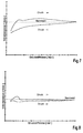
- the invention has for its object a flow controller with in the preamble of claim 1 Design specified features so that at great constancy of the volume flow in wide differential pressure ranges a high initial steepness of the characteristic the controller has a low hysteresis with changing rising and falling pressure and high stability the characteristic over the operating time will.
- the special design of the regulator disc with a tapered flattening of the to the controller holder indicative side ensures a high initial steepness the controller characteristic curve and the one on it Side trained narrow ribs and / or sector-shaped Bridges contribute to a low hysteresis combined with quick responsiveness.
- a “narrow rib” in the sense of the invention is understood to be a rib, the width of which is only one Fraction of the disk diameter corresponds to while under a “sector-shaped footbridge” a little broader area to be understood, which is sector-shaped over a circumferential angle of the disk extends, which can be larger than 90 °. this will further below using the exemplary embodiments explained.
- the flow regulator shown in the drawings exists basically of three parts, namely the Regulator socket 1, the regulator disc 2 and the diffuser 3.
- the controller socket 1 is in the illustrated embodiment one essentially on both sides pot-shaped component with a bottom 1.1, a forward-facing side wall 1.2 and one rear-facing side wall 1.3.
- the forward facing side wall 1.2 opens conically outwards and is elastic.
- the bottom 1.1 points Openings 4, which are symmetrical to the axial Direction are arranged.
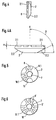
- the regulator disk 2 used in the version 1 is in a first embodiment in Figs. 4, 4A and 5 shown.
- the regulator disc is on the pentagonal pin 5 2 by means of an appropriately pentagonal Center holes 7 put on.
- the regulator disk 2 consists of elastically deformable Material, for example an elastomer and has on the front, i.e. the upstream side, a strong one cone-shaped bevel 2.2, which a predetermined Has angle ⁇ to the axial direction X. The one with it achieved volume reduction leaves the regulator disc react even with small pressure changes.
- On the The rear of the regulator disk 2 is located in the edge area a small bevel with a given one Angle ⁇ , which can be 1 ° to 5 °.
- each depressions 10 are each depressions 10. Furthermore 5 in the embodiment according to FIG certain circumferential area a sector-shaped web 8.1 with a given circumferential angle greater than 90 ° arranged.
- the structured rear is increasingly included expanding areas on the pot bottom 1.1 and closes the openings 4.
- the slight slope 2.1 supported on the back of the regulator disc 2 a steep increase in the volume flow characteristic combined with a low hysteresis in the event of pressure fluctuations. Because of the shape described the regulator disk 2 is a further for the material Tolerance for tolerance of hardness permitted.
- n is a natural number larger 3 and expediently less than 10.
- the diffuser 3 is a rotationally symmetrical one Component and points evenly from its Center outgoing spokes 9 on. It is used for beam shaping of the fluid flowing through the regulator.
- the Diffuser 3 initially acts as a flow resistance for the medium emerging from the regulator holder.
- the spokes 9 are designed and arranged that between the downstream and opening ends End 6.1 of the bypass hole and the spokes there is a predetermined distance. In the space between the regulator socket 2 and the diffuser 3 distributed the medium then spreads evenly and leaves through the Spaces of the spoke 9 directed the controller.
- the flow regulator according to the invention works as follows:
- the flow regulator is in suitable mounting holes of fittings, safety devices, jet regulators or pipe pieces pushed, the funnel-shaped Widening of the outer wall facing forward 1.2 sealing against the wall of the mounting hole creates.
- the flow pressure of the flowing medium towards FL acts on the regulator disk 2 such that the narrow ribs 8 or the sector-shaped Web 8.1 and the remaining surface of the back the regulator disc gradually to the base of the frame 1.1 create.
- This is part of the passage cross-sections of the openings 4 covered so that the free flow channels and the bypass hole 6 of the socket determine the volume flow the increasing pressure difference also becomes the deepened Surfaces 10 between the ribs 8 of the disc 2 in pressed the free cross sections of the socket, so that the volume flow is reduced so that a straight curve is created.
- the Disc thanks to its elastic properties more flow cross-section free and thus equalizes the volume flow its setpoint automatically.
Landscapes
- Engineering & Computer Science (AREA)
- Mechanical Engineering (AREA)
- General Engineering & Computer Science (AREA)
- Physics & Mathematics (AREA)
- General Physics & Mathematics (AREA)
- Automation & Control Theory (AREA)
- Flow Control (AREA)
- Infusion, Injection, And Reservoir Apparatuses (AREA)
- Sampling And Sample Adjustment (AREA)
- Endoscopes (AREA)
- Cookers (AREA)
- Safety Valves (AREA)
- Fittings On The Vehicle Exterior For Carrying Loads, And Devices For Holding Or Mounting Articles (AREA)
- Float Valves (AREA)
- Feeding And Controlling Fuel (AREA)
- Containers And Packaging Bodies Having A Special Means To Remove Contents (AREA)
- Domestic Plumbing Installations (AREA)
- Valve Housings (AREA)
- Pipe Accessories (AREA)
Abstract
Description
- Fig. 1
- einen Mengenregler im Längsschnitt;
- Fig. 2
- die Vorderansicht des Reglers nach Fig. 1;
- Fig. 3
- die Rückansicht des Reglers nach Fig. 1;
- Fig. 4
- die Reglerscheibe des Reglers nach Fig. 1 bis 3 in Seitenansicht;
- Fig.4A
- eine vergrößerte Darstellung der Reglerscheibe nach Fig. 4;
- Fig.5
- die Rückseite einer ersten Ausführungsform der Reglerscheibe;
- Fig. 6
- in einer Darstellung analog Fig. 5 die Rückseite einer anderen Ausführungsform der Reglerscheibe;
- Fig. 7
- eine Kennlinie eines Mengenreglers gemäß dem Stand der Technik;
- Fig. 8
- eine Kennlinie eines erfindungsgemäßen Mengenreglers.
Claims (6)
- In eine Flüssigkeitsleitung oder Aufnahmebohrung einer Armatur einsetzbarer Mengenregler mit einer im wesentlichen topfförmigen Fassung, deren Boden Durchbrechungen aufweist und in die eine Reglerscheibe aus elastisch verformbarem Material eingesetzt ist, dadurch gekennzeichnet, daß die dem Topfboden (1.1) zugewandte Stirnfläche der Reglerscheibe (2) mindestens in ihrem Randbereich eine kegelflächenförmige Abflachung (2.1) mit einem Neigungswinkel von 1° bis 5° zur Scheibenmittelebene aufweist und mit im wesentlichen radial in vorgegebenen Winkelabständen verlaufenden schmalen Rippen (8) und/oder sektorförmigen Stegen (8.1), die sich über einen vorgegebenen Umfangswinkel erstrecken, versehen ist.
- Mengenregler nach Anspruch 1, dadurch gekennzeichnet, daß der Topfboden (1.1) n (n > 3) symmetrisch zur axialen Richtung angeordnete Durchbrechungen (4) und einen im Querschnitt höchstens n-1-eckigen Mittelzapfen (5) aufweist, auf den die Reglerscheibe (2) mit einem im Querschnitt entsprechend n-1-eckigen konzentrisch angeordneten Loch (7) aufgesteckt ist.
- Mengenregler nach Anspruch 2, dadurch gekennzeichnet, daß bei sechs Durchbrechungen (4) im Topfboden (1.1) die Reglerscheibe (2) ein im Querschnitt fünfeckiges Mittelloch (7) besitzt und auf einen Fünfkantzapfen (5) des Topfbodens (1.1) aufgesteckt ist.
- Mengenregler nach einem der Ansprüche 1 bis 3, dadurch gekennzeichnet, daß die vom Topfboden (1.1) abgewandte Anströmseite der Reglerscheibe (2) kegelstumpfförmig (2.2) ausgebildet ist.
- Mengenregler nach einem der Ansprüche 1 bis 4, dadurch gekennzeichnet, daß die Fassung (1) eine konzentrische Bypaßbohrung (6) aufweist.
- Mengenregler nach Anspruch 5, dadurch gekennzeichnet, daß die Fassung (2) mit einem Diffusor (3) verbunden ist, der als Scheibe mit mehreren, vom Mittelpunkt radial zum Scheibenrand verlaufenden Speichen (9) ausgebildet ist, wobei das stromabwärts gelegene Ende (6.1) der Bypaßbohrung (6) einen vorgegebenen Abstand von den Speichen (9) besitzt.
Applications Claiming Priority (2)
| Application Number | Priority Date | Filing Date | Title |
|---|---|---|---|
| DE19641233A DE19641233A1 (de) | 1996-10-07 | 1996-10-07 | In eine Flüssigkeitsleitung oder die Aufnahmebohrung einer Armatur einsetzbarer Mengenregler |
| DE19641233 | 1997-09-09 |
Publications (2)
| Publication Number | Publication Date |
|---|---|
| EP0838743A1 true EP0838743A1 (de) | 1998-04-29 |
| EP0838743B1 EP0838743B1 (de) | 1999-07-14 |
Family
ID=7808033
Family Applications (1)
| Application Number | Title | Priority Date | Filing Date |
|---|---|---|---|
| EP97116589A Expired - Lifetime EP0838743B1 (de) | 1996-10-07 | 1997-09-24 | In eine Flüssigkeitsleitung oder die Aufnahmebohrung einer Armatur einsetzbarer Mengenregler |
Country Status (6)
| Country | Link |
|---|---|
| US (1) | US5899224A (de) |
| EP (1) | EP0838743B1 (de) |
| AT (1) | ATE182221T1 (de) |
| DE (2) | DE19641233A1 (de) |
| DK (1) | DK0838743T3 (de) |
| ES (1) | ES2134666T3 (de) |
Cited By (1)
| Publication number | Priority date | Publication date | Assignee | Title |
|---|---|---|---|---|
| US6695011B2 (en) | 2002-05-07 | 2004-02-24 | Dieter Wildfang Gmbh | Flow regulator |
Families Citing this family (10)
| Publication number | Priority date | Publication date | Assignee | Title |
|---|---|---|---|---|
| EP0937903A3 (de) * | 1998-02-24 | 2000-11-08 | Mannesmann Sachs Aktiengesellschaft | Drosselglied für hydraulische Verstelleinrichtungen bei Kraftfahrzeugen |
| US6378542B1 (en) * | 2000-07-21 | 2002-04-30 | Emerson Electric Co. | Flow control device having a lip seal and compressible bypass pads and associated method for operating an appliance water valve |
| US7225829B2 (en) * | 2004-10-22 | 2007-06-05 | Vernay Laboratories, Inc. | Flow-control valve assembly |
| US7222642B2 (en) * | 2005-10-27 | 2007-05-29 | Emerson Electric Co. | Enhanced water valve tube stop |
| US8091587B1 (en) | 2010-01-28 | 2012-01-10 | David Schwartz | Tamper-resistant water flow restriction system |
| US8567445B2 (en) | 2011-10-03 | 2013-10-29 | D.S. Magic Tech Llc | Water flow restriction device and method |
| US9777857B2 (en) * | 2016-01-08 | 2017-10-03 | Pao-Tang Chen | Flow control valve |
| DE202017101398U1 (de) * | 2017-03-10 | 2018-06-12 | Neoperl Gmbh | Sanitäres Einsetzteil und Verwendung eines solchen |
| CN108505589B (zh) * | 2018-05-29 | 2024-02-23 | 路达(厦门)工业有限公司 | 一种流量自调节起泡器 |
| DE202019104935U1 (de) * | 2019-09-06 | 2020-12-08 | Neoperl Gmbh | Durchflussmengenregler |
Citations (3)
| Publication number | Priority date | Publication date | Assignee | Title |
|---|---|---|---|---|
| WO1982001573A1 (en) * | 1980-11-03 | 1982-05-13 | Walter R Nelson | Flow control device employing elastomeric element |
| EP0492111A2 (de) * | 1990-12-21 | 1992-07-01 | DIETER WILDFANG GmbH | Durchflussregler |
| DE29520069U1 (de) * | 1994-12-19 | 1996-02-08 | Elbi Int Spa | Hydraulischer Durchsatzregler |
Family Cites Families (24)
| Publication number | Priority date | Publication date | Assignee | Title |
|---|---|---|---|---|
| US530442A (en) * | 1894-12-04 | Pump-valve | ||
| US1154962A (en) * | 1914-02-05 | 1915-09-28 | Ingersoll Rand Co | Flow-controlling valve for conduits. |
| US2777464A (en) * | 1951-03-07 | 1957-01-15 | Detroit Controls Corp | Flow control devices |
| US2674262A (en) * | 1951-03-30 | 1954-04-06 | William D Bradshaw | Rate of flow valve |
| US2801067A (en) * | 1951-10-23 | 1957-07-30 | Mercier Jean | Closure valve for the oil port of a pressure accumulator |
| US2880758A (en) * | 1953-12-09 | 1959-04-07 | Mercier Jean | Closure valve for the outlet port of a pressure accumulator |
| US2939487A (en) * | 1957-08-21 | 1960-06-07 | Speakman Co | Flow control device |
| US2948296A (en) * | 1958-03-24 | 1960-08-09 | Powers Regulator Co | Variable constant flow device |
| US3228418A (en) * | 1962-09-12 | 1966-01-11 | Bendix Corp | Check valve |
| US3473561A (en) * | 1966-03-29 | 1969-10-21 | Bert N Svenson | Check valve with supported closure member |
| DE1658232B2 (de) * | 1967-05-18 | 1975-09-04 | American Radiator & Standard Sanitary Corp., New York, N.Y. (V.St.A.) | Auslaufmundstück für Wassereinläufe von Badewannen o.dgl |
| DE1750923B2 (de) * | 1968-06-19 | 1972-11-30 | Danfoss A/S, Nordborg (Dänemark) | Drosseleinrichtung zum konstanthalten einer durchflussmenge |
| US3911949A (en) * | 1973-12-03 | 1975-10-14 | Aero Tec Lab Inc | Safety fueling valve |
| DE2729458C3 (de) * | 1977-06-30 | 1981-07-16 | Arcu Armaturindustri AB, Alstermo | Strömungsregulator, insbesondere zum Einbau zwischen einem Wasserkran und einem Wasserleitungsende |
| US4325366A (en) * | 1980-07-07 | 1982-04-20 | Tabor Carl J | Valve and method for use with a tracheotomy tube |
| DE3223206C2 (de) * | 1982-06-22 | 1985-02-07 | Danfoss A/S, Nordborg | Durchflußmengenregler |
| DE3437013C2 (de) * | 1984-10-09 | 1994-03-10 | Dieter Kuhn | Durchflußregler für den Einsatz in Flüssigkeitsleitungen |
| DE8429669U1 (de) * | 1984-10-09 | 1985-02-28 | Kuhn, Dieter, 6229 Schlangenbad | Durchfluss-begrenzer fuer fluessigkeiten |
| DE8434013U1 (de) * | 1984-11-20 | 1985-03-28 | Schülke & Mayr GmbH, 2000 Norderstedt | Dosiervorrichtung |
| US4805661A (en) * | 1985-12-05 | 1989-02-21 | Masco Corporation Of Indiana | Faucet valve with anti-siphon back flow preventer |
| DE8604762U1 (de) * | 1986-02-22 | 1986-04-17 | Kobold, Klaus, Dipl.-Ing., 6233 Kelkheim | Regelventil |
| US5226446A (en) * | 1991-06-25 | 1993-07-13 | Eaton Corporation | Flow noise reduction |
| US5507318A (en) * | 1994-10-04 | 1996-04-16 | Walbro Corporation | Umbrella check valves |
| DE29601623U1 (de) * | 1996-01-31 | 1996-03-14 | Dieter Wildfang GmbH, 79379 Müllheim | Durchflußmengenregler o.dgl. Drossel |
-
1996
- 1996-10-07 DE DE19641233A patent/DE19641233A1/de not_active Withdrawn
-
1997
- 1997-09-24 ES ES97116589T patent/ES2134666T3/es not_active Expired - Lifetime
- 1997-09-24 EP EP97116589A patent/EP0838743B1/de not_active Expired - Lifetime
- 1997-09-24 AT AT97116589T patent/ATE182221T1/de not_active IP Right Cessation
- 1997-09-24 DE DE59700257T patent/DE59700257D1/de not_active Expired - Fee Related
- 1997-09-24 DK DK97116589T patent/DK0838743T3/da active
- 1997-10-07 US US08/946,281 patent/US5899224A/en not_active Expired - Lifetime
Patent Citations (3)
| Publication number | Priority date | Publication date | Assignee | Title |
|---|---|---|---|---|
| WO1982001573A1 (en) * | 1980-11-03 | 1982-05-13 | Walter R Nelson | Flow control device employing elastomeric element |
| EP0492111A2 (de) * | 1990-12-21 | 1992-07-01 | DIETER WILDFANG GmbH | Durchflussregler |
| DE29520069U1 (de) * | 1994-12-19 | 1996-02-08 | Elbi Int Spa | Hydraulischer Durchsatzregler |
Cited By (1)
| Publication number | Priority date | Publication date | Assignee | Title |
|---|---|---|---|---|
| US6695011B2 (en) | 2002-05-07 | 2004-02-24 | Dieter Wildfang Gmbh | Flow regulator |
Also Published As
| Publication number | Publication date |
|---|---|
| ATE182221T1 (de) | 1999-07-15 |
| DK0838743T3 (da) | 2000-01-31 |
| EP0838743B1 (de) | 1999-07-14 |
| DE19641233A1 (de) | 1998-04-09 |
| ES2134666T3 (es) | 1999-10-01 |
| DE59700257D1 (de) | 1999-08-19 |
| US5899224A (en) | 1999-05-04 |
Similar Documents
| Publication | Publication Date | Title |
|---|---|---|
| EP2210157B1 (de) | Durchflussbegrenzer | |
| EP0838743B1 (de) | In eine Flüssigkeitsleitung oder die Aufnahmebohrung einer Armatur einsetzbarer Mengenregler | |
| DE3520491A1 (de) | Regelorgan fuer gasfoermige und fluessige medien | |
| DE923365C (de) | Gas- und Fluessigkeits-Kontaktapparat | |
| EP0271765A2 (de) | Eigenmediumgesteuertes, durch ein vorzugsweise elektromagnetisch betätigtes Steuerventil auslösbares Ventil | |
| DE2729458B2 (de) | Strömungsregulator, insbesondere zum Einbau zwischen einem Wasserkran und einem Wasserleitungsende | |
| EP3054058A1 (de) | Sanitäre einsetzeinheit | |
| CH676429A5 (de) | ||
| EP0475097A2 (de) | Durchflussregler | |
| DE3206357A1 (de) | Temperaturempfindliches umgehungsventil mit integraler druckentlastung | |
| EP0182327A1 (de) | Vorrichtung zur drosselnden Durchflussbegrenzung in Wasser-Armaturen | |
| DE69014869T2 (de) | Druckregelungsventil. | |
| EP0059887B1 (de) | Entspannungsventil | |
| WO2020074382A1 (de) | Sitzventil, ventilkomponenten eines sitzventils, sowie verfahren zum herstellen von ventilkomponenten eines sitzventils | |
| DE19851151C2 (de) | Durchflussbegrenzer für Sanitärarmaturen | |
| DE4302036C2 (de) | Als Wechseldrossel ausgeführtes Steuerorgan | |
| EP1378693B1 (de) | Heizkörperventil | |
| DE29623993U1 (de) | In eine Flüssigkeitsleitung oder die Aufnahmebohrung einer Armatur einsetzbarer Mengenregler | |
| DE102015206205A1 (de) | Gasventil | |
| DE3707192A1 (de) | Sicherheitsarmatur | |
| DE1548932B2 (de) | Durchfluß Mengenregler | |
| DE1201139B (de) | Ventil aus elastischem Werkstoff mit veraenderlichem Durchflussquerschnitt | |
| DE19743740C2 (de) | Mehrstufiger Durchflußmengenregler nach dem Elastomerring-Verformprinzip | |
| DE102019110073A1 (de) | Strömungswiderstandseinsatz und Durchflussmess- oder Durchflussregeleinrichtung | |
| DE29520069U1 (de) | Hydraulischer Durchsatzregler |
Legal Events
| Date | Code | Title | Description |
|---|---|---|---|
| PUAI | Public reference made under article 153(3) epc to a published international application that has entered the european phase |
Free format text: ORIGINAL CODE: 0009012 |
|
| AK | Designated contracting states |
Kind code of ref document: A1 Designated state(s): AT CH DE DK ES FR GB IT LI NL SE |
|
| AX | Request for extension of the european patent |
Free format text: AL;LT;LV;RO;SI |
|
| 17P | Request for examination filed |
Effective date: 19980311 |
|
| GRAG | Despatch of communication of intention to grant |
Free format text: ORIGINAL CODE: EPIDOS AGRA |
|
| 17Q | First examination report despatched |
Effective date: 19980903 |
|
| GRAG | Despatch of communication of intention to grant |
Free format text: ORIGINAL CODE: EPIDOS AGRA |
|
| GRAH | Despatch of communication of intention to grant a patent |
Free format text: ORIGINAL CODE: EPIDOS IGRA |
|
| AKX | Designation fees paid |
Free format text: AT CH DE DK ES FR GB IT LI NL SE |
|
| RBV | Designated contracting states (corrected) |
Designated state(s): AT CH DE DK ES FR GB IT LI NL SE |
|
| GRAH | Despatch of communication of intention to grant a patent |
Free format text: ORIGINAL CODE: EPIDOS IGRA |
|
| GRAA | (expected) grant |
Free format text: ORIGINAL CODE: 0009210 |
|
| AK | Designated contracting states |
Kind code of ref document: B1 Designated state(s): AT CH DE DK ES FR GB IT LI NL SE |
|
| REF | Corresponds to: |
Ref document number: 182221 Country of ref document: AT Date of ref document: 19990715 Kind code of ref document: T |
|
| REG | Reference to a national code |
Ref country code: CH Ref legal event code: NV Representative=s name: A. BRAUN, BRAUN, HERITIER, ESCHMANN AG PATENTANWAE Ref country code: CH Ref legal event code: EP |
|
| REF | Corresponds to: |
Ref document number: 59700257 Country of ref document: DE Date of ref document: 19990819 |
|
| ET | Fr: translation filed | ||
| REG | Reference to a national code |
Ref country code: ES Ref legal event code: FG2A Ref document number: 2134666 Country of ref document: ES Kind code of ref document: T3 |
|
| GBT | Gb: translation of ep patent filed (gb section 77(6)(a)/1977) |
Effective date: 19990914 |
|
| REG | Reference to a national code |
Ref country code: DK Ref legal event code: T3 |
|
| PLBE | No opposition filed within time limit |
Free format text: ORIGINAL CODE: 0009261 |
|
| STAA | Information on the status of an ep patent application or granted ep patent |
Free format text: STATUS: NO OPPOSITION FILED WITHIN TIME LIMIT |
|
| 26N | No opposition filed | ||
| REG | Reference to a national code |
Ref country code: GB Ref legal event code: IF02 |
|
| PGFP | Annual fee paid to national office [announced via postgrant information from national office to epo] |
Ref country code: SE Payment date: 20020827 Year of fee payment: 6 |
|
| PGFP | Annual fee paid to national office [announced via postgrant information from national office to epo] |
Ref country code: GB Payment date: 20020828 Year of fee payment: 6 Ref country code: FR Payment date: 20020828 Year of fee payment: 6 |
|
| PGFP | Annual fee paid to national office [announced via postgrant information from national office to epo] |
Ref country code: ES Payment date: 20020829 Year of fee payment: 6 Ref country code: AT Payment date: 20020829 Year of fee payment: 6 |
|
| PGFP | Annual fee paid to national office [announced via postgrant information from national office to epo] |
Ref country code: DK Payment date: 20020917 Year of fee payment: 6 |
|
| PGFP | Annual fee paid to national office [announced via postgrant information from national office to epo] |
Ref country code: CH Payment date: 20020927 Year of fee payment: 6 |
|
| PGFP | Annual fee paid to national office [announced via postgrant information from national office to epo] |
Ref country code: NL Payment date: 20020930 Year of fee payment: 6 |
|
| PG25 | Lapsed in a contracting state [announced via postgrant information from national office to epo] |
Ref country code: GB Free format text: LAPSE BECAUSE OF NON-PAYMENT OF DUE FEES Effective date: 20030924 Ref country code: AT Free format text: LAPSE BECAUSE OF NON-PAYMENT OF DUE FEES Effective date: 20030924 |
|
| PG25 | Lapsed in a contracting state [announced via postgrant information from national office to epo] |
Ref country code: SE Free format text: LAPSE BECAUSE OF NON-PAYMENT OF DUE FEES Effective date: 20030925 Ref country code: ES Free format text: LAPSE BECAUSE OF NON-PAYMENT OF DUE FEES Effective date: 20030925 |
|
| PG25 | Lapsed in a contracting state [announced via postgrant information from national office to epo] |
Ref country code: LI Free format text: LAPSE BECAUSE OF NON-PAYMENT OF DUE FEES Effective date: 20030930 Ref country code: DK Free format text: LAPSE BECAUSE OF NON-PAYMENT OF DUE FEES Effective date: 20030930 Ref country code: CH Free format text: LAPSE BECAUSE OF NON-PAYMENT OF DUE FEES Effective date: 20030930 |
|
| PG25 | Lapsed in a contracting state [announced via postgrant information from national office to epo] |
Ref country code: NL Free format text: LAPSE BECAUSE OF NON-PAYMENT OF DUE FEES Effective date: 20040401 |
|
| EUG | Se: european patent has lapsed | ||
| REG | Reference to a national code |
Ref country code: DK Ref legal event code: EBP |
|
| GBPC | Gb: european patent ceased through non-payment of renewal fee |
Effective date: 20030924 |
|
| REG | Reference to a national code |
Ref country code: CH Ref legal event code: PL |
|
| PG25 | Lapsed in a contracting state [announced via postgrant information from national office to epo] |
Ref country code: FR Free format text: LAPSE BECAUSE OF NON-PAYMENT OF DUE FEES Effective date: 20040528 |
|
| NLV4 | Nl: lapsed or anulled due to non-payment of the annual fee |
Effective date: 20040401 |
|
| REG | Reference to a national code |
Ref country code: FR Ref legal event code: ST |
|
| PGFP | Annual fee paid to national office [announced via postgrant information from national office to epo] |
Ref country code: DE Payment date: 20041007 Year of fee payment: 8 |
|
| REG | Reference to a national code |
Ref country code: ES Ref legal event code: FD2A Effective date: 20030925 |
|
| PG25 | Lapsed in a contracting state [announced via postgrant information from national office to epo] |
Ref country code: IT Free format text: LAPSE BECAUSE OF NON-PAYMENT OF DUE FEES Effective date: 20050924 |
|
| PG25 | Lapsed in a contracting state [announced via postgrant information from national office to epo] |
Ref country code: DE Free format text: LAPSE BECAUSE OF NON-PAYMENT OF DUE FEES Effective date: 20060401 |