EP0838833A2 - Vorform einer Fluoreszenslampe, mit solcher Vorform gefertigte Fluoreszenslampe und Herstellungsverfahren - Google Patents
Vorform einer Fluoreszenslampe, mit solcher Vorform gefertigte Fluoreszenslampe und Herstellungsverfahren Download PDFInfo
- Publication number
- EP0838833A2 EP0838833A2 EP97116435A EP97116435A EP0838833A2 EP 0838833 A2 EP0838833 A2 EP 0838833A2 EP 97116435 A EP97116435 A EP 97116435A EP 97116435 A EP97116435 A EP 97116435A EP 0838833 A2 EP0838833 A2 EP 0838833A2
- Authority
- EP
- European Patent Office
- Prior art keywords
- bulb
- fluorescent lamp
- stem
- lamp
- preform
- Prior art date
- Legal status (The legal status is an assumption and is not a legal conclusion. Google has not performed a legal analysis and makes no representation as to the accuracy of the status listed.)
- Granted
Links
Images

Classifications
-
- H—ELECTRICITY
- H01—ELECTRIC ELEMENTS
- H01J—ELECTRIC DISCHARGE TUBES OR DISCHARGE LAMPS
- H01J9/00—Apparatus or processes specially adapted for the manufacture, installation, removal, maintenance of electric discharge tubes, discharge lamps, or parts thereof; Recovery of material from discharge tubes or lamps
- H01J9/24—Manufacture or joining of vessels, leading-in conductors or bases
- H01J9/245—Manufacture or joining of vessels, leading-in conductors or bases specially adapted for gas discharge tubes or lamps
- H01J9/247—Manufacture or joining of vessels, leading-in conductors or bases specially adapted for gas discharge tubes or lamps specially adapted for gas-discharge lamps
-
- H—ELECTRICITY
- H01—ELECTRIC ELEMENTS
- H01J—ELECTRIC DISCHARGE TUBES OR DISCHARGE LAMPS
- H01J9/00—Apparatus or processes specially adapted for the manufacture, installation, removal, maintenance of electric discharge tubes, discharge lamps, or parts thereof; Recovery of material from discharge tubes or lamps
- H01J9/38—Exhausting, degassing, filling, or cleaning vessels
-
- H—ELECTRICITY
- H01—ELECTRIC ELEMENTS
- H01J—ELECTRIC DISCHARGE TUBES OR DISCHARGE LAMPS
- H01J61/00—Gas-discharge or vapour-discharge lamps
- H01J61/02—Details
- H01J61/30—Vessels; Containers
-
- H—ELECTRICITY
- H01—ELECTRIC ELEMENTS
- H01J—ELECTRIC DISCHARGE TUBES OR DISCHARGE LAMPS
- H01J61/00—Gas-discharge or vapour-discharge lamps
- H01J61/02—Details
- H01J61/36—Seals between parts of vessels; Seals for leading-in conductors; Leading-in conductors
-
- H—ELECTRICITY
- H01—ELECTRIC ELEMENTS
- H01J—ELECTRIC DISCHARGE TUBES OR DISCHARGE LAMPS
- H01J61/00—Gas-discharge or vapour-discharge lamps
- H01J61/64—Cathode glow lamps
Definitions
- This invention relates to a preform for a fluorescent lamp for use as an indicating lamp so-called a single-end type fluorescent lamp, a fluorescent lamp prepared by the preform and a method for preparing the fluorescent lamp, particularly to a single-end type fluorescent lamp provided with a feeder unit at one end portion of a bulb to be suitable for use as an indicating lamp for an apparatus or a light emission element for an electric sign board.
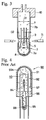
- Fig. 4 shows the configuration of this type of a fluorescent lamp 90 for use as an indicating lamp of the prior art which is constructed by welding a bulb 91 whose inner surface is coated with a fluorescent material 92 to a stem 96 provided with a filament 93 coated with an electron emission substance 93a, a discharge electrode 94, and an exhaust pipe 95 in advance and exhausting inside air from the exhaust pipe 95, charging an inert gas 97 and mercury 98 into the bulb 92 and heat sealing this exhaust pipe 95 to seal the fluorescent lamp 90.
- the sealing of the fluorescent lamp is achieved by heat-sealing the exhaust pipe 95, it is inevitable in the process that the exhaust pipe 95 projects from the stem 96.
- the mercury 98 charged in the lamp tends to be liquefied in the exhaust pipe 95 having a lower temperature and to stay therein in a liquid state.
- the filament 93 When the filament 93 is applied voltage to turn on the fluorescent lamp 90 for use as an indicating lamp, it takes a long time for the heat of the filament 93 to reach the mercury 98 in the exhaust pipe 95 located farther than the stem 96 from the filament and evaporate the mercury 98 thereby. As a result, a long time is required from the start of lighting until the characteristics of the lamp becomes stable.
- the exhaust pipe 95 projects, when an indicating unit, for example, is formed by mounting the fluorescent lamp 90 for use as an indicating lamp on a substrate, the exhaust pipe 95 may be broken by contacting it to the substrate and the fluorescent lamp 90 for use as an indicating lamp itself may be broken. Thus, a handling problem may occur.
- An object of the present invention as means for solving the problems of the prior art is to provide a preform for a fluorescent lamp, in which the preform comprises a bulb having a bulb body portion which forms a bulb body of the fluorescent lamp and an exhausting pipe portion through which inside air is exhausted and inert gas and mercury is charged, an inner surface of the bulb body portion being coated with a fluorescent material, and a stem provided with a filament coated with an electron emission substance and a discharge electrode, in which the stem is inserted into the bulb to set a predetermined position, and the inner diameter of the bulb is made larger than the outer diameter of the stem so as to from a space therebetween for enabling inside air to be exhausted from the inside of the bulb and inert gas and mercury to be charged into the inside of the bulb therethrough.
- Another object of the present invention is to provide a preform for a fluorescent lamp as above, in which the bulb further comprises a projection formed on an inner surface of the bulb so as to set the inserted stem at the predetermined position.
- Still another object of the present invention is to provide a fluorescent lamp for use as an indicating lamp, in which the fluorescent lamp is prepared by the preform as above.
- Another object of the present invention is to provide a method for preparing a fluorescent lamp for use as an indicating lamp, the method comprising the steps of:
- a still further object of the present invention is to provide a method for preparing a fluorescent lamp for use as an indicating lamp as above, in which the bulb further comprises a projection formed on an inner surface of the bulb so as to set the inserted stem at the predetermined position.
- reference numeral 1 denotes a fluorescent lamp for use as an indicating lamp according to the present invention (to be simply referred to as "fluorescent lamp 1" hereinafter).
- the fluorescent lamp 1 is of a single-end type fluorescent lamp comprising a bulb 2 whose inner surface is coated with a fluorescent material 9, and a stem 3 provided with a filament 5 coated with an electron emission substance 5a, and a discharge electrode 5 so as to form a discharge chamber 4 by welding the bulb 2 to the stem 3 like the prior art.
- An inert gas 7 such as argon, neon, krypton or xenon and an appropriate amount of mercury 8 are charged into the discharge chamber 4 like the prior art. However, in the present invention, no exhaust pipe is provided in the stem 3.
- FIG. 2 and fig. 3 show an example of the production process of the fluorescent lamp 1 of the present invention configured as described above.
- a preform of the fluorescent lamp 1 comprises the bulb 2 having a bulb portion 2a which forms a bulb body of the fluorescent lamp 1 and is coated with the florescent material 9 and an exhausting pipe portion 2b through which inside air is exhausted and inert gas and mercury are charged, and the stem inserted into the bulb 2.
- the inner diameter D1 of the bulb 2 is suitably made larger than the outer diameter D2 of the stem 3 and there is an appropriate space therebetween when the stem 3 is inserted into the bulb 2.
- the bulb 2 of the preform has an appropriate length so that the exhausting pipe portion 2b can be directly connected to an exhaust head 10 of an exhausting machine for exhausting inside air and charging inert gas and mercury thereinto (not shown) while the stem 3 is inserted in the bulb 2. Further a projection 2c is formed on the inner surface of the bulb 2 so that the stem 3 is set at a predetermined position when the stem 3 is inserted into the bulb 2.
- the bulb 2 formed as described above is connected to the exhaust head 10 while the stem 3 is inserted in the bulb 2 as shown in Fig. 2. Therefore, the stem 3 is contacted to the projection 2c by its weight and can be positioned at a predetermined location in the bulb 2.
- air in the bulb portion 2a the inside of which becomes the discharge chamber 4 after sealing is exhausted through the above space between the bulb 2 and the stem 3 and the inside of the bulb 2 becomes vacuum.
- the inert gas 7 and the mercury 8 are then supplied into the bulb 2, the inert gas 7 is spread into the bulb portion 2a of the bulb 2 which becomes the discharge chamber 4 through the space and the mercury 8 having a high specific gravity collects in a lower end portion of the bulb 2 in this state throrgh the space as shown in Fig. 2.
- a location where the stem 3 is positioned is heated by a burner 11 from the outside of the bulb 2 to weld the bulb 2 to the stem 3 and an unrequired portion of the bulb 2, i.e. the exhausting pipe portion 2b is removed thereby, the fluorescent lamp 1 without an exhaust pipe, which the present invention is directed to, can be obtained.
- the mounting operation can be made without paying attention not to break an exhaust pipe. Further, it is possible to arrange the fluorescent lamp 1 in close contact with the substrate, thereby improving variation for mounting and arranging the fluorescent lamp on a substrate.
- the present invention since a fluorescent lamp for use as an indicating lamp is constructed without any exhaust pipe, liquefied mercury is present in the discharge chamber near the filament and thus easily receives a large amount of heat from the filament at the time of turning on the lamp. Therefore, the liquefied mercury is evaporated quickly, whereby the characteristics of the lamp become stable quickly after turning on the lamp.
- the present invention provides an extremely excellent effect that the performance of the fluorescent lamp for use as an indicating lamp is improved.
- the present invention provides an effect that handling operation is simplified. Further, it is possible to arrange the fluorescent lamp for use as an indicating lamp in close contact with the substrate due to the absence of the exhaust pipe. Therefore, the present invention provides an excellent effect that variation for mounting and arranging the fluorescent lamps on a substrate is improved to reduce the size of the indicating panel.
Landscapes
- Engineering & Computer Science (AREA)
- Manufacturing & Machinery (AREA)
- Vessels And Coating Films For Discharge Lamps (AREA)
- Manufacture Of Electron Tubes, Discharge Lamp Vessels, Lead-In Wires, And The Like (AREA)
Applications Claiming Priority (3)
| Application Number | Priority Date | Filing Date | Title |
|---|---|---|---|
| JP283923/96 | 1996-10-25 | ||
| JP8283923A JPH10125231A (ja) | 1996-10-25 | 1996-10-25 | 標示灯用蛍光ランプ |
| JP28392396 | 1996-10-25 |
Publications (3)
| Publication Number | Publication Date |
|---|---|
| EP0838833A2 true EP0838833A2 (de) | 1998-04-29 |
| EP0838833A3 EP0838833A3 (de) | 1998-06-03 |
| EP0838833B1 EP0838833B1 (de) | 1999-10-06 |
Family
ID=17671966
Family Applications (1)
| Application Number | Title | Priority Date | Filing Date |
|---|---|---|---|
| EP97116435A Expired - Lifetime EP0838833B1 (de) | 1996-10-25 | 1997-09-20 | Vorformling einer Fluoreszenslampe, mit einem derartigen Vorformling gefertigte Fluoreszenslampe und Herstellungsverfahren |
Country Status (4)
| Country | Link |
|---|---|
| US (1) | US5932970A (de) |
| EP (1) | EP0838833B1 (de) |
| JP (1) | JPH10125231A (de) |
| DE (1) | DE69700586T2 (de) |
Cited By (2)
| Publication number | Priority date | Publication date | Assignee | Title |
|---|---|---|---|---|
| US6104134A (en) * | 1997-08-20 | 2000-08-15 | Stanley Electric Co., Ltd. | Fluorescent lamp |
| US6121728A (en) * | 1998-01-29 | 2000-09-19 | Stanley Electric Co., Ltd. | Fluorescent lamp having the cathode and anode with particular angular arrangement |
Families Citing this family (1)
| Publication number | Priority date | Publication date | Assignee | Title |
|---|---|---|---|---|
| CN100543921C (zh) * | 2004-10-29 | 2009-09-23 | 清华大学 | 场发射发光照明光源 |
Family Cites Families (10)
| Publication number | Priority date | Publication date | Assignee | Title |
|---|---|---|---|---|
| JPS57111931A (en) * | 1980-12-27 | 1982-07-12 | Stanley Electric Co Ltd | Manufacture of mercury lamp |
| DE3139732A1 (de) * | 1981-10-06 | 1983-04-21 | Patent-Treuhand-Gesellschaft für elektrische Glühlampen mbH, 8000 München | Einseitig gesockelte niederdruckentladungslampe und verfahren zur herstellung |
| JPS58108634A (ja) * | 1981-12-21 | 1983-06-28 | Toshiba Corp | 「あ」光ランプの製造方法 |
| JPH0719565B2 (ja) * | 1986-07-07 | 1995-03-06 | ウエスト電気株式会社 | 閃光放電管 |
| JP2862638B2 (ja) * | 1990-06-08 | 1999-03-03 | 株式会社東芝 | 自動化学分析装置 |
| JPH0443964A (ja) * | 1990-06-08 | 1992-02-13 | Kansei Corp | 回転センサ |
| US5176558A (en) * | 1991-05-01 | 1993-01-05 | Gte Products Corporation | Methods for removing contaminants from arc discharge lamps |
| US5432403A (en) * | 1991-06-10 | 1995-07-11 | Gte Products Corporation | Negative glow discharge lamp having improved color stability and enhanced life |
| JP2686721B2 (ja) * | 1994-08-26 | 1997-12-08 | シーケーディ株式会社 | 小型蛍光ランプの製造方法 |
| FR2738938A1 (fr) * | 1995-09-20 | 1997-03-21 | Philips Electronics Nv | Dispositif de telecommande d'un appareil recepteur video |
-
1996
- 1996-10-25 JP JP8283923A patent/JPH10125231A/ja active Pending
-
1997
- 1997-09-20 DE DE69700586T patent/DE69700586T2/de not_active Expired - Fee Related
- 1997-09-20 EP EP97116435A patent/EP0838833B1/de not_active Expired - Lifetime
- 1997-10-03 US US08/943,745 patent/US5932970A/en not_active Expired - Fee Related
Cited By (2)
| Publication number | Priority date | Publication date | Assignee | Title |
|---|---|---|---|---|
| US6104134A (en) * | 1997-08-20 | 2000-08-15 | Stanley Electric Co., Ltd. | Fluorescent lamp |
| US6121728A (en) * | 1998-01-29 | 2000-09-19 | Stanley Electric Co., Ltd. | Fluorescent lamp having the cathode and anode with particular angular arrangement |
Also Published As
| Publication number | Publication date |
|---|---|
| DE69700586T2 (de) | 2000-05-04 |
| JPH10125231A (ja) | 1998-05-15 |
| US5932970A (en) | 1999-08-03 |
| EP0838833B1 (de) | 1999-10-06 |
| EP0838833A3 (de) | 1998-06-03 |
| DE69700586D1 (de) | 1999-11-11 |
Similar Documents
| Publication | Publication Date | Title |
|---|---|---|
| US5108333A (en) | Method of making a double-ended high-pressure discharge lamp | |
| US5932970A (en) | Preform for fluorescent lamp, fluorescent lamp prepared by the same, and method for preparing the fluorescent lamp | |
| US5323087A (en) | Ultraviolet radiation starting source and lamp containing same | |
| HU177548B (en) | Head for electric light source making machine,with such heads providede light source making machine,as well as,method for making electric light sources | |
| US5248273A (en) | Method of fabricating ultraviolet radiation starting source | |
| EP0604221B1 (de) | Leuchtstofflampe | |
| US7876051B2 (en) | Electrode mount, arc tube, low-pressure mercury vapor discharge lamp, compact self-ballasted fluorescent lamp and method of manufacturing the arc tube | |
| JPH10321135A (ja) | 高圧放電ランプおよびその製造方法 | |
| US7775847B2 (en) | Method for manufacturing hot cathode fluorescent lamp | |
| JP3314462B2 (ja) | 蛍光ランプ装置 | |
| JP2871499B2 (ja) | 冷陰極蛍光ランプの製造方法 | |
| JPH01102844A (ja) | 低圧水銀蒸気放電灯 | |
| JP3006761U (ja) | チップレス放電管 | |
| EP0801417A2 (de) | Zweiseitig gesockelte Halogenlampe und Herstellungsverfahren derselbe | |
| JPS6147055A (ja) | 螢光ランプ | |
| JPH058863U (ja) | 放電ランプ | |
| JPH01243339A (ja) | 蛍光ランプの製造方法 | |
| JPH11233067A (ja) | 放電灯及びその製造方法 | |
| JPS638051Y2 (de) | ||
| JPH1050253A (ja) | ランプおよび照明装置 | |
| JPH08273614A (ja) | 冷陰極蛍光ランプ及びその製造方法 | |
| JPH0434830A (ja) | 冷陰極蛍光ランプ | |
| JPH05205641A (ja) | 無電極放電ランプの製造方法 | |
| JPH0330238A (ja) | 無電極放電ランプの製造方法 | |
| JPH0388235A (ja) | 蛍光ランプの製造方法 |
Legal Events
| Date | Code | Title | Description |
|---|---|---|---|
| PUAI | Public reference made under article 153(3) epc to a published international application that has entered the european phase |
Free format text: ORIGINAL CODE: 0009012 |
|
| PUAL | Search report despatched |
Free format text: ORIGINAL CODE: 0009013 |
|
| AK | Designated contracting states |
Kind code of ref document: A2 Designated state(s): AT BE |
|
| AK | Designated contracting states |
Kind code of ref document: A3 Designated state(s): AT BE CH DE DK ES FI FR GB GR IE IT LI LU MC NL PT SE |
|
| 17P | Request for examination filed |
Effective date: 19980820 |
|
| GRAG | Despatch of communication of intention to grant |
Free format text: ORIGINAL CODE: EPIDOS AGRA |
|
| AKX | Designation fees paid |
Free format text: DE GB |
|
| RBV | Designated contracting states (corrected) |
Designated state(s): DE GB |
|
| 17Q | First examination report despatched |
Effective date: 19990209 |
|
| GRAG | Despatch of communication of intention to grant |
Free format text: ORIGINAL CODE: EPIDOS AGRA |
|
| GRAH | Despatch of communication of intention to grant a patent |
Free format text: ORIGINAL CODE: EPIDOS IGRA |
|
| GRAH | Despatch of communication of intention to grant a patent |
Free format text: ORIGINAL CODE: EPIDOS IGRA |
|
| GRAA | (expected) grant |
Free format text: ORIGINAL CODE: 0009210 |
|
| AK | Designated contracting states |
Kind code of ref document: B1 Designated state(s): DE GB |
|
| REF | Corresponds to: |
Ref document number: 69700586 Country of ref document: DE Date of ref document: 19991111 |
|
| PLBE | No opposition filed within time limit |
Free format text: ORIGINAL CODE: 0009261 |
|
| STAA | Information on the status of an ep patent application or granted ep patent |
Free format text: STATUS: NO OPPOSITION FILED WITHIN TIME LIMIT |
|
| 26N | No opposition filed | ||
| REG | Reference to a national code |
Ref country code: GB Ref legal event code: IF02 |
|
| PGFP | Annual fee paid to national office [announced via postgrant information from national office to epo] |
Ref country code: DE Payment date: 20020725 Year of fee payment: 6 |
|
| PGFP | Annual fee paid to national office [announced via postgrant information from national office to epo] |
Ref country code: GB Payment date: 20020828 Year of fee payment: 6 |
|
| PG25 | Lapsed in a contracting state [announced via postgrant information from national office to epo] |
Ref country code: GB Free format text: LAPSE BECAUSE OF NON-PAYMENT OF DUE FEES Effective date: 20030920 |
|
| PG25 | Lapsed in a contracting state [announced via postgrant information from national office to epo] |
Ref country code: DE Free format text: LAPSE BECAUSE OF NON-PAYMENT OF DUE FEES Effective date: 20040401 |
|
| GBPC | Gb: european patent ceased through non-payment of renewal fee |
Effective date: 20030920 |