EP0838877A2 - Réflecteurs déployables - Google Patents
Réflecteurs déployables Download PDFInfo
- Publication number
- EP0838877A2 EP0838877A2 EP97308214A EP97308214A EP0838877A2 EP 0838877 A2 EP0838877 A2 EP 0838877A2 EP 97308214 A EP97308214 A EP 97308214A EP 97308214 A EP97308214 A EP 97308214A EP 0838877 A2 EP0838877 A2 EP 0838877A2
- Authority
- EP
- European Patent Office
- Prior art keywords
- reflector
- ribs
- reflective surface
- deployable
- deployable reflector
- Prior art date
- Legal status (The legal status is an assumption and is not a legal conclusion. Google has not performed a legal analysis and makes no representation as to the accuracy of the status listed.)
- Withdrawn
Links
Images




Classifications
-
- H—ELECTRICITY
- H01—ELECTRIC ELEMENTS
- H01Q—ANTENNAS, i.e. RADIO AERIALS
- H01Q1/00—Details of, or arrangements associated with, antennas
- H01Q1/27—Adaptation for use in or on movable bodies
- H01Q1/28—Adaptation for use in or on aircraft, missiles, satellites, or balloons
- H01Q1/288—Satellite antennas
-
- H—ELECTRICITY
- H01—ELECTRIC ELEMENTS
- H01Q—ANTENNAS, i.e. RADIO AERIALS
- H01Q15/00—Devices for reflection, refraction, diffraction or polarisation of waves radiated from an antenna, e.g. quasi-optical devices
- H01Q15/14—Reflecting surfaces; Equivalent structures
- H01Q15/141—Apparatus or processes specially adapted for manufacturing reflecting surfaces
-
- H—ELECTRICITY
- H01—ELECTRIC ELEMENTS
- H01Q—ANTENNAS, i.e. RADIO AERIALS
- H01Q15/00—Devices for reflection, refraction, diffraction or polarisation of waves radiated from an antenna, e.g. quasi-optical devices
- H01Q15/14—Reflecting surfaces; Equivalent structures
- H01Q15/16—Reflecting surfaces; Equivalent structures curved in two dimensions [2D], e.g. paraboloidal
- H01Q15/161—Collapsible reflectors
Definitions
- This invention relates to deployable reflectors.
- the invention especially relates to deployable reflectors for communication satellites.
- a typical reflector for a satellite would be a solid structure, constructed of honeycomb-type material, about 31 ⁇ 2 metres in diameter. Any larger size would be difficult to stow prior to launch.
- Such reflectors are used in some cases for mobile telephones, but a relatively large mobile telephone is required eg. briefcase size.
- the reflector has to be unfurlable.
- unfurlable reflector is the umbrella type, in which the ribs are pivoted towards each other to provide a compact structure.
- Another type of unfurlable reflector is the expanding type in which a structure unfolds or expands to tension a mesh or membrane (GB-A-2 120 857), but this type tends to be expensive and heavy.
- Inflatable structures have also been proposed, but these can go out of shape when thermal stresses or even solar winds are encountered if used in large sizes such as would be needed for the mobile telephone application.
- the invention provides a deployable reflector (2) for a space-craft (1), comprising a flexible reflective surface (9) carried by expandable support means (8), characterised in that the surface carries at least one strip (11, 12) impregnated with or coated with a resin system which was cured when the reflective surface was in the shape desired for the reflective surface when unfurled, this strip being elastically deformed when the reflector is stowed.
- the reflective surface When the reflector is unfurled, the reflective surface returns to its preformed shape. With such a design it is possible to provide a large area of reflective surface which can still be stowed to a convenient size for launch.
- the expandable support means comprises a plurality of ribs which, when the reflector is unfurled, extend along generators of a paraboloid over a region off-set from the centre of the paraboloid; and a hinge at one end of each of the ribs to enable the ribs to be pivoted to stow the reflector for launch.
- the ribs may also have hinges at one or more points along their lengths, to enable even larger surfaces to be deployed without increasing the size when stowed.
- the invention also provides a method of making the reflective surface of a deployable reflector for a space-craft, comprising the steps of applying a strip impregnated or coated with a resin system to a material when in the shape desired for the reflective surface after unfurling, and curing the resin system while the material maintains that shape.
- the communications satellite has the usual components such as solar panels, multiple antennas etc. but the only part illustrated in the drawings is one unfurlable reflector. Together with its feed horn, the reflector forms an antenna.
- the satellite 1 carries the reflector 2 on a pair of arms 3 (one arm only could be used if desired) at the sides of the space-craft, and the reflector is an off-set parabolic reflector.
- the reflecting surface 2 lies on the surface of a parabola 4, but does not include the central region around the centre of the paraboloid 5.
- Many unfurlable reflectors are actually of the latter type, but the problem with this is that the feed horn, which must be located at the focus 6 of the paraboloid would actually obscure the beam transmitted or received by the antenna.
- the off-set reflector 2 of the invention receives beams from a number of feed horns 7 mounted on the side of the satellite 1, the horns being so aligned that the beams strike the reflector 2 in the direction taken had they been transmitted from the focus 6 of the paraboloid of which the off-set reflector forms a part. It will immediately be seen that this results in a parallel beam A-A being generated which would usually be directed downwardly at a region of the earth.
- the satellite might well be positioned in a geostationary orbit. In fact there will not just be one beam A-A. In fact there will be many such beams, in order to create a pattern of spots on the earth surface which overlap to a sufficient extent to enable cells to be defined for mobile phone usage. A large number of beams is desired so that the same frequency can be used many times.
- Such a communication satellite with an off-set reflector is known, but the invention is concerned with the facility to make very large reflectors, for example up to 12 metres in diameter, to permit effective coverage, for example, in underdeveloped regions, using only a small mobile telephone.
- the antenna may operate both for transmit and for receive.
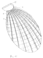
- This large size of reflector which folds up conveniently for launch, consists of a number of ribs 8, which carry a flexible reflective surface 9.
- each rib 8 while they are actually of different lengths, nevertheless each lies on the generator of the parent paraboloid.
- the term "generator” is used to mean a line which lies on the surface of the parent paraboloid and passes through its centre 5 and which when swept around in a circle such as dotted circle B, generates the paraboloidal shape.
- These ribs 8 are hinged to a rail 10 which is carried by the side arms 3.
- the ribs 8 when the satellite is in a stowed condition, the ribs 8 are hinged in towards the space-craft 1, and do not greatly increase the footprint of the satellite 1 in the direction of ascent of the rocket.
- the reflective material 9 is not shown for the sake of clarity.
- the ribs 8 are held remote from the rail 10 by some securing system (not shown) which is released when the deployment mechanism is operated.
- the ribs 8 all form part of a generator, which of course has a parabolic shape, then there need be only one parabolic shaped tool from which to manufacture the ribs.
- the reflective surface 9 may be mesh or membrane, and may consist of a metallised plastics material reinforced with fabric. If mesh, the reflective material may be knitted out of wire such as gold plated molybdenum.
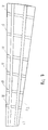
- FIG. 7 represents a segment between two adjacent ribs 8 in the view shown in Figure 2. Once again, it will be apparent that the segment lies on a segment of the surface of the parent paraboloid.
- the reflective surface which consists of metallised plastics such as Kapton (RTM) reinforced with fabric such as Kevlar (RTM), which is not impregnated with any curing agent, is laid over a tool shaped like a segment of the surface of the paraboloid corresponding to the angular separation of two adjacent ribs 8.
- strips such as fabric strips, which are impregnated with or coated with a curing system, are laid over this material which has been pressed against the segment-shaped former.
- a number of transverse strips 11 are first of all laid across the segment, and then radial strips 12 are laid over these strips 11. While the shape is being held against the former, curing is made to take place, which means that the segment now has a preformed shape corresponding to the desired surface of the segment of the surface of the paraboloid.
- extension system for the ribs 8 may be used, for example, springs, or for example the Applicant's powered hinge described in our European Patent Application No. 505134.
- An advantage of providing the feed horn 7 directly on one side of the satellite is that losses in the signal to the feed horns, which can be in the region of kilowatts, is minimised.
- the antenna can operate in the L-band.
- FIG. 8 A practical embodiment of the folding ribs is shown in Figures 8 to 10.
- the feed horn means 7 is shown schematically in Figure 8 but is not shown in Figure 9.
- a mounting structure 15 is shown in place of the arms 3.
Landscapes
- Physics & Mathematics (AREA)
- Engineering & Computer Science (AREA)
- Electromagnetism (AREA)
- Astronomy & Astrophysics (AREA)
- General Physics & Mathematics (AREA)
- Remote Sensing (AREA)
- Manufacturing & Machinery (AREA)
- Aviation & Aerospace Engineering (AREA)
- Aerials With Secondary Devices (AREA)
- Details Of Aerials (AREA)
Applications Claiming Priority (2)
| Application Number | Priority Date | Filing Date | Title |
|---|---|---|---|
| GB9622022A GB2318688A (en) | 1996-10-24 | 1996-10-24 | Deployable reflector |
| GB9622022 | 1996-10-24 |
Publications (2)
| Publication Number | Publication Date |
|---|---|
| EP0838877A2 true EP0838877A2 (fr) | 1998-04-29 |
| EP0838877A3 EP0838877A3 (fr) | 1998-12-16 |
Family
ID=10801817
Family Applications (1)
| Application Number | Title | Priority Date | Filing Date |
|---|---|---|---|
| EP97308214A Withdrawn EP0838877A3 (fr) | 1996-10-24 | 1997-10-16 | Réflecteurs déployables |
Country Status (2)
| Country | Link |
|---|---|
| EP (1) | EP0838877A3 (fr) |
| GB (1) | GB2318688A (fr) |
Cited By (2)
| Publication number | Priority date | Publication date | Assignee | Title |
|---|---|---|---|---|
| FR2835099A1 (fr) * | 2002-01-18 | 2003-07-25 | Lacroix Soc E | Reflecteur electromagnetique a jonc deployable |
| US9755318B2 (en) | 2014-01-09 | 2017-09-05 | Northrop Grumman Systems Corporation | Mesh reflector with truss structure |
Families Citing this family (2)
| Publication number | Priority date | Publication date | Assignee | Title |
|---|---|---|---|---|
| RU2336615C1 (ru) * | 2006-12-15 | 2008-10-20 | Федеральное государственное унитарное предприятие "Всероссийский научно-исследовательский институт "Градиент" | Многолучевая зеркальная антенна |
| RU2541871C2 (ru) * | 2013-07-09 | 2015-02-20 | Российская Федерация, От Имени Которой Выступает Министерство Промышленности И Торговли Российской Федерации | Сверхширокополосная многолучевая зеркальная антенна |
Family Cites Families (6)
| Publication number | Priority date | Publication date | Assignee | Title |
|---|---|---|---|---|
| US4030103A (en) * | 1975-12-10 | 1977-06-14 | Lockheed Missiles & Space Company, Inc. | Deployable offset paraboloid antenna |
| US4191604A (en) * | 1976-01-07 | 1980-03-04 | General Dynamics Corporation Pomona Division | Method of constructing three-dimensionally curved, knit wire reflector |
| US4527166A (en) * | 1981-03-26 | 1985-07-02 | Luly Robert A | Lightweight folding parabolic reflector and antenna system |
| DE3338937A1 (de) * | 1983-10-27 | 1985-05-09 | Messerschmitt-Bölkow-Blohm GmbH, 8012 Ottobrunn | Entfaltbarer antennen-netzreflektor |
| DE3532851A1 (de) * | 1985-09-14 | 1987-04-16 | Messerschmitt Boelkow Blohm | Entfalt- und wiedereinfaltbarer antennenreflektor |
| US4845511A (en) * | 1987-01-27 | 1989-07-04 | Harris Corp. | Space deployable domed solar concentrator with foldable panels and hinge therefor |
-
1996
- 1996-10-24 GB GB9622022A patent/GB2318688A/en not_active Withdrawn
-
1997
- 1997-10-16 EP EP97308214A patent/EP0838877A3/fr not_active Withdrawn
Cited By (3)
| Publication number | Priority date | Publication date | Assignee | Title |
|---|---|---|---|---|
| FR2835099A1 (fr) * | 2002-01-18 | 2003-07-25 | Lacroix Soc E | Reflecteur electromagnetique a jonc deployable |
| US6864824B2 (en) | 2002-01-18 | 2005-03-08 | Etienne Lacroix Tous Artifices S.A. | Electromagnetic reflector |
| US9755318B2 (en) | 2014-01-09 | 2017-09-05 | Northrop Grumman Systems Corporation | Mesh reflector with truss structure |
Also Published As
| Publication number | Publication date |
|---|---|
| GB2318688A (en) | 1998-04-29 |
| GB9622022D0 (en) | 1996-12-18 |
| EP0838877A3 (fr) | 1998-12-16 |
Similar Documents
| Publication | Publication Date | Title |
|---|---|---|
| US6104358A (en) | Low cost deployable reflector | |
| US5990851A (en) | Space deployable antenna structure tensioned by hinged spreader-standoff elements distributed around inflatable hoop | |
| JP3291481B2 (ja) | 光電池アレイおよび展開可能rf反射器の組合わせ構造 | |
| US5680145A (en) | Light-weight reflector for concentrating radiation | |
| EP0749177B1 (fr) | Réflecteurs d'antenne pour un véhicule spatial et système de retenue et d'arrimage de tels réflecteurs | |
| US6963315B2 (en) | Inflatable antenna | |
| US6373449B1 (en) | Hybrid inflatable antenna | |
| JPH0633697Y2 (ja) | 多通信系衛星軌道宇宙船 | |
| JP4202267B2 (ja) | 宇宙ベースのレーダのための膨張可能な反射器アンテナ | |
| EP3654452B1 (fr) | Réflecteur d'antenne à maillage à périmètre déployable | |
| US3521290A (en) | Self-erecting reflector | |
| CN111092285B (zh) | 一种星载可展开抛物柱面天线 | |
| JP4876941B2 (ja) | 展開型アンテナ | |
| JP2010537880A (ja) | ペイロード中心構成を有する宇宙船 | |
| GB2328560A (en) | Antenna reflector attached by tensionable means to inflatable support | |
| WO2002025767A1 (fr) | Deploiement d'un reflecteur a balayage electronique | |
| WO2002101880A1 (fr) | Antenne a reflecteur deployable a architecture de soutien a tensegrite et procedes associes | |
| JP7459237B2 (ja) | アンテナ用展開式アセンブリ | |
| JP2001060812A (ja) | 二反射器システムの展開 | |
| Rogers et al. | Technology assessment and development of large deployable antennas | |
| JP7359370B2 (ja) | アンテナ用展開可能反射器 | |
| GB2318688A (en) | Deployable reflector | |
| US20030234746A1 (en) | Sub-reflector shaping in an unfurlable reflector antenna system | |
| US7151509B2 (en) | Apparatus for use in providing wireless communication and method for use and deployment of such apparatus | |
| JP4160928B2 (ja) | パラボラ反射鏡 |
Legal Events
| Date | Code | Title | Description |
|---|---|---|---|
| PUAI | Public reference made under article 153(3) epc to a published international application that has entered the european phase |
Free format text: ORIGINAL CODE: 0009012 |
|
| AK | Designated contracting states |
Kind code of ref document: A2 Designated state(s): AT BE CH DE DK ES FI FR GB GR IE IT LI LU MC NL PT SE |
|
| AX | Request for extension of the european patent |
Free format text: AL;LT;LV;RO;SI |
|
| RIN1 | Information on inventor provided before grant (corrected) |
Inventor name: DUNBAR, NEIL WILLIAM Inventor name: CLEMMET, JAMES FRANCIS, DR. |
|
| PUAL | Search report despatched |
Free format text: ORIGINAL CODE: 0009013 |
|
| AK | Designated contracting states |
Kind code of ref document: A3 Designated state(s): AT BE CH DE DK ES FI FR GB GR IE IT LI LU MC NL PT SE |
|
| AX | Request for extension of the european patent |
Free format text: AL;LT;LV;RO;SI |
|
| AKX | Designation fees paid | ||
| STAA | Information on the status of an ep patent application or granted ep patent |
Free format text: STATUS: THE APPLICATION IS DEEMED TO BE WITHDRAWN |
|
| 18D | Application deemed to be withdrawn |
Effective date: 20000502 |
|
| REG | Reference to a national code |
Ref country code: DE Ref legal event code: 8566 |