EP0838894A1 - Convertisseur de courant electrique pour des vehicules electrique a courant alternatif - Google Patents
Convertisseur de courant electrique pour des vehicules electrique a courant alternatif Download PDFInfo
- Publication number
- EP0838894A1 EP0838894A1 EP95924523A EP95924523A EP0838894A1 EP 0838894 A1 EP0838894 A1 EP 0838894A1 EP 95924523 A EP95924523 A EP 95924523A EP 95924523 A EP95924523 A EP 95924523A EP 0838894 A1 EP0838894 A1 EP 0838894A1
- Authority
- EP
- European Patent Office
- Prior art keywords
- overhead line
- voltage
- line voltage
- power
- service
- Prior art date
- Legal status (The legal status is an assumption and is not a legal conclusion. Google has not performed a legal analysis and makes no representation as to the accuracy of the status listed.)
- Withdrawn
Links
- 230000001172 regenerating effect Effects 0.000 claims abstract description 39
- 238000001514 detection method Methods 0.000 claims abstract description 18
- 230000000630 rising effect Effects 0.000 claims description 2
- 230000006698 induction Effects 0.000 description 3
- 239000003990 capacitor Substances 0.000 description 2
- 238000010586 diagram Methods 0.000 description 2
- 238000009499 grossing Methods 0.000 description 2
- 239000004065 semiconductor Substances 0.000 description 2
- 238000006243 chemical reaction Methods 0.000 description 1
- 230000006866 deterioration Effects 0.000 description 1
- 230000000694 effects Effects 0.000 description 1
- 230000006641 stabilisation Effects 0.000 description 1
- 238000011105 stabilization Methods 0.000 description 1
- 230000000087 stabilizing effect Effects 0.000 description 1
- 230000009466 transformation Effects 0.000 description 1
- 230000001131 transforming effect Effects 0.000 description 1
- 238000004804 winding Methods 0.000 description 1
Images


Classifications
-
- H—ELECTRICITY
- H02—GENERATION; CONVERSION OR DISTRIBUTION OF ELECTRIC POWER
- H02M—APPARATUS FOR CONVERSION BETWEEN AC AND AC, BETWEEN AC AND DC, OR BETWEEN DC AND DC, AND FOR USE WITH MAINS OR SIMILAR POWER SUPPLY SYSTEMS; CONVERSION OF DC OR AC INPUT POWER INTO SURGE OUTPUT POWER; CONTROL OR REGULATION THEREOF
- H02M1/00—Details of apparatus for conversion
- H02M1/42—Circuits or arrangements for compensating for or adjusting power factor in converters or inverters
- H02M1/4208—Arrangements for improving power factor of AC input
- H02M1/4233—Arrangements for improving power factor of AC input using a bridge converter comprising active switches
-
- B—PERFORMING OPERATIONS; TRANSPORTING
- B60—VEHICLES IN GENERAL
- B60L—PROPULSION OF ELECTRICALLY-PROPELLED VEHICLES; SUPPLYING ELECTRIC POWER FOR AUXILIARY EQUIPMENT OF ELECTRICALLY-PROPELLED VEHICLES; ELECTRODYNAMIC BRAKE SYSTEMS FOR VEHICLES IN GENERAL; MAGNETIC SUSPENSION OR LEVITATION FOR VEHICLES; MONITORING OPERATING VARIABLES OF ELECTRICALLY-PROPELLED VEHICLES; ELECTRIC SAFETY DEVICES FOR ELECTRICALLY-PROPELLED VEHICLES
- B60L9/00—Electric propulsion with power supply external to the vehicle
- B60L9/16—Electric propulsion with power supply external to the vehicle using AC induction motors
- B60L9/24—Electric propulsion with power supply external to the vehicle using AC induction motors fed from AC supply lines
- B60L9/28—Electric propulsion with power supply external to the vehicle using AC induction motors fed from AC supply lines polyphase motors
-
- H—ELECTRICITY
- H02—GENERATION; CONVERSION OR DISTRIBUTION OF ELECTRIC POWER
- H02M—APPARATUS FOR CONVERSION BETWEEN AC AND AC, BETWEEN AC AND DC, OR BETWEEN DC AND DC, AND FOR USE WITH MAINS OR SIMILAR POWER SUPPLY SYSTEMS; CONVERSION OF DC OR AC INPUT POWER INTO SURGE OUTPUT POWER; CONTROL OR REGULATION THEREOF
- H02M5/00—Conversion of AC power input into AC power output, e.g. for change of voltage, for change of frequency, for change of number of phases
- H02M5/40—Conversion of AC power input into AC power output, e.g. for change of voltage, for change of frequency, for change of number of phases with intermediate conversion into DC
- H02M5/42—Conversion of AC power input into AC power output, e.g. for change of voltage, for change of frequency, for change of number of phases with intermediate conversion into DC by static converters
- H02M5/44—Conversion of AC power input into AC power output, e.g. for change of voltage, for change of frequency, for change of number of phases with intermediate conversion into DC by static converters using discharge tubes or semiconductor devices to convert the intermediate DC into AC
- H02M5/443—Conversion of AC power input into AC power output, e.g. for change of voltage, for change of frequency, for change of number of phases with intermediate conversion into DC by static converters using discharge tubes or semiconductor devices to convert the intermediate DC into AC using devices of a thyratron or thyristor type requiring extinguishing means
- H02M5/45—Conversion of AC power input into AC power output, e.g. for change of voltage, for change of frequency, for change of number of phases with intermediate conversion into DC by static converters using discharge tubes or semiconductor devices to convert the intermediate DC into AC using devices of a thyratron or thyristor type requiring extinguishing means using semiconductor devices only
- H02M5/4505—Conversion of AC power input into AC power output, e.g. for change of voltage, for change of frequency, for change of number of phases with intermediate conversion into DC by static converters using discharge tubes or semiconductor devices to convert the intermediate DC into AC using devices of a thyratron or thyristor type requiring extinguishing means using semiconductor devices only having a rectifier with controlled elements
-
- H—ELECTRICITY
- H02—GENERATION; CONVERSION OR DISTRIBUTION OF ELECTRIC POWER
- H02M—APPARATUS FOR CONVERSION BETWEEN AC AND AC, BETWEEN AC AND DC, OR BETWEEN DC AND DC, AND FOR USE WITH MAINS OR SIMILAR POWER SUPPLY SYSTEMS; CONVERSION OF DC OR AC INPUT POWER INTO SURGE OUTPUT POWER; CONTROL OR REGULATION THEREOF
- H02M7/00—Conversion of AC power input into DC power output; Conversion of DC power input into AC power output
- H02M7/02—Conversion of AC power input into DC power output without possibility of reversal
- H02M7/04—Conversion of AC power input into DC power output without possibility of reversal by static converters
- H02M7/12—Conversion of AC power input into DC power output without possibility of reversal by static converters using discharge tubes with control electrode or semiconductor devices with control electrode
- H02M7/145—Conversion of AC power input into DC power output without possibility of reversal by static converters using discharge tubes with control electrode or semiconductor devices with control electrode using devices of a thyratron or thyristor type requiring extinguishing means
- H02M7/155—Conversion of AC power input into DC power output without possibility of reversal by static converters using discharge tubes with control electrode or semiconductor devices with control electrode using devices of a thyratron or thyristor type requiring extinguishing means using semiconductor devices only
- H02M7/1552—Conversion of AC power input into DC power output without possibility of reversal by static converters using discharge tubes with control electrode or semiconductor devices with control electrode using devices of a thyratron or thyristor type requiring extinguishing means using semiconductor devices only in a biphase or polyphase arrangement
-
- Y—GENERAL TAGGING OF NEW TECHNOLOGICAL DEVELOPMENTS; GENERAL TAGGING OF CROSS-SECTIONAL TECHNOLOGIES SPANNING OVER SEVERAL SECTIONS OF THE IPC; TECHNICAL SUBJECTS COVERED BY FORMER USPC CROSS-REFERENCE ART COLLECTIONS [XRACs] AND DIGESTS
- Y02—TECHNOLOGIES OR APPLICATIONS FOR MITIGATION OR ADAPTATION AGAINST CLIMATE CHANGE
- Y02B—CLIMATE CHANGE MITIGATION TECHNOLOGIES RELATED TO BUILDINGS, e.g. HOUSING, HOUSE APPLIANCES OR RELATED END-USER APPLICATIONS
- Y02B70/00—Technologies for an efficient end-user side electric power management and consumption
- Y02B70/10—Technologies improving the efficiency by using switched-mode power supplies [SMPS], i.e. efficient power electronics conversion e.g. power factor correction or reduction of losses in power supplies or efficient standby modes
Definitions
- the present invention relates to an electric vehicle receiving power from an AC overhead line and, more particularly, to a power converter for an AC electric vehicle including power factor control means, connected with a control apparatus for controlling an electric vehicle driving motor, for achieving delivery and receipt, between the control apparatus and the overhead line, of power accompanying service operation and regenerative operation of the motor by controlling the power factor on the AC side.
- An object of the present invention is to provide a power converter for an AC electric vehicle capable of stabilizing the overhead line voltage and preventing deterioration in the service performance and the regenerative braking performance.
- the above mentioned object can be achieved by providing a power converter for an AC electric vehicle with power factor control means, the AC side of which is connected with an AC overhead line through a transformer and the DC side of which is connected with a control apparatus of a motor for driving the electric vehicle, for achieving delivery and receipt, between the control apparatus and the AC overhead line, of power accompanying service operation and regenerative operation of the motor by controlling the power factor on the AC side,
- the power converter comprising DC voltage control means for controlling the voltage on the DC side of the converter to assume a predetermined value, service/regenerative operation detection means for detecting whether the motor is in service operation or in regenerative operation, and overhead line voltage detection means for detecting the voltage on the overhead line
- the power factor control means includes means responsive to detection signals from the overhead line voltage detection means and the service/regenerative operation detection means for controlling the power factor on the AC side such that variations in the overhead line voltage accompanying the service and regenerative operations of the motor are suppressed.
- the voltage on the AC side of the power converter can always be kept at a predetermined value, though the reactive power may sometimes become greater by execution of such control (because no control is made to keep the power factor at unity).
- the DC voltage becomes greater than the AC voltage on the side of the overhead line, and the power corresponding to the difference can be regenerated on the side of the overhead line. Therefore, the invention as the power converter for an AC electric vehicle gives a good regenerative braking performance.
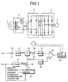
- FIG. 1 is a structural drawing of a power converter showing an embodiment of the invention
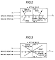
- FIG. 2 shows an embodiment of the ⁇ setting device in FIG. 1
- FIG. 3 shows another embodiment of the ⁇ setting device in FIG. 1
- FIG. 4 is a drawing explanatory of the operation of a self commutated converter of the present invention.
- FIG. 5 is a drawing explanatory of the impedance in a feeder system used for explanation of the principle of the invention
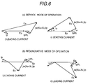
- FIG. 6 is a drawing showing the relationship between the substation voltage E S and the overhead line voltage E P used for explaining the principle of the invention
- FIG. 7 is a drawing showing the relationship between the phase and the overhead line voltage used for explaining the principle of the invention.
- FIG. 6 schematically shows impedance in a feeder system.
- the substation is denoted by reference numeral 1, the reactive component of the transformer in the substation by X S , the resistive component of the overhead line by R L , and the reactive component of the overhead line by X L .
- X S 7.44 ⁇
- R L 0.28 ⁇ /Km
- X L 0.769 ⁇ /Km.
- E S delivery voltage from the substation not including the reactance X S
- E P voltage at the pantograph point of the electric vehicle
- the power converter for electric vehicle comprises a transformer 2 for transforming the overhead line voltage to a voltage convenient to handle, a PWM converter 3 for converting the AC voltage from the transformer into a DC voltage, a PWM inverter 4 for converting the DC voltage into an AC voltage for controlling an induction motor 5, and the like.
- FIG. 6 shows vector diagrams indicating the relationship between the overhead line voltage E P and the substation delivery voltage E S in the mode of service operation and the mode of regenerative operation.
- E S (E P + I P R L cos ⁇ + I P X L sin ⁇ ) 2 + (I P X L cos ⁇ - I P R L sin ⁇ ) 2
- E P P / (E P ⁇ cos ⁇ ) .
- E P 1 2 ⁇ E 2 S -2P(R L +X L tan ⁇ )+ E 4 S -4P(R L +X L tan ⁇ )E 2 S -4P 2 (X L +R L tan ⁇ ) 2 ⁇
- the overhead line voltage tends to slightly lower.
- the overhead line voltage is lowered by existence of other electric vehicles in service operation (the overhead line voltage largely falls when there are present other vehicles provided with conventional external commutated converters and they consume lagging currents with a power factors of around 0.8)
- the overhead line voltage E P can be recovered by controlling the phase of the current I P controlled by the PWM converter 3 to shift into its lagging direction and thus stabilization of the overhead line voltage E P can be achieved without impairing the service operating performances of other electric vehicles in service operation.
- AC power supplied from an AC power supply 1 such as a substation through an overhead line is taken in by a pantograph not shown and supplied to a transformer 2.
- the transformer 2 is connected to a pulse width modulation (PWM) converter 3 as a self commutated converter through an inductance L T (which is concurrently used as the transformer winding).
- PWM pulse width modulation
- the DC side of the PWM converter 3 is connected to a three-phase PWM inverter 4 through a smoothing capacitor 6.
- the PWM converter 3 operates so that the DC voltage V d assumes a predetermined value.
- the DC voltage command V d * and the DC voltage V d detected as the voltage across the smoothing capacitor 6 are compared in an adder 10 and the difference between them is input to a voltage regulator 11.
- the voltage regulator 11 outputs a crest value command I sm of the current I s to be passed through the AC side of the PWM converter 3.
- the voltage E s of the AC power supply 1 picked out of the secondary side of the transformer 2 is divided by its crest value E sm in a divider 14 to be converted into a unit sine wave, sin ⁇ t , and sin ⁇ t and the crest value command I sm output from the voltage regulator 11 are multiplied in a multiplier 12 and, thereby, an instantaneous AC current command I s * is generated.
- This instantaneous AC current command I s * and the PWM converter output current I s are compared in an adder 13 and the difference between them is input to a current regulator 17.
- the current regulator 17 outputs a modulation wave corresponding to the AC voltage command for the PWM converter and, thereupon, the modulation wave and a triangular wave generated by a triangular wave generator 18 are compared in a comparator 19 and a pulse width modulation signal is output therefrom.
- This signal is amplified in a gate circuit 20 and used for ON-OFF controlling the self arc suppressing switching elements constituting the PWM converter 3.
- FIG. 4(a) shows the service mode of operation. Control is executed such that the phase of the output voltage from the converter is caused to lag the power supply voltage E S and the voltage difference between the voltage E S and the input voltage to the converter E C , i.e., the voltage applied to the inductance L T within the transformer 2, assumes the phase leading the power supply voltage E S by 90° . As a result, the current I s flowing through L T is rendered in phase with the power supply voltage E S .
- FIG. 4(b) shows the regenerative mode of operation.
- control is executed such that the input voltage E C to the converter is caused to lead the power supply voltage E S and the voltage difference between E S and E C , i.e., the voltage applied to the inductance L T within the transformer 2, assumes the phase lagging the power supply voltage E S by 90° .
- the current I S flowing through L T is rendered 180° out of phase with the power supply voltage E S .
- the voltage signal of the AC power supply 1 (E P can be obtained by reversely calculating the overhead line voltage from the transformer secondary voltage E S and the transformation ratio or, when E P is unobtainable from E S on account of the internal inductance L T , E P may be obtained directly.) is calculated from the unit sine wave signal sin ⁇ t by the divider 14.
- a unit sine wave sin( ⁇ t - ⁇ ) with the phase lagging the phase of the AC power supply E S by ⁇ or so is output from an ⁇ setting device, which determines whether the mode is for service operation or for regenerative braking operation and, where the mode is for service operation, the phase of lead ⁇ is set negative when the overhead line voltage E P is low, and where the mode is for regenerative braking operation, the phase of lead ⁇ is set negative when the overhead line voltage E P is high.
- the signal is multiplied by I sm , and the command I s * for the instantaneous value of the AC current to be passed through the inductance L T of the transformer 2 is obtained.
- FIG. 2 and FIG. 3 show examples of such ⁇ setting device.
- the example shown in FIG. 2 is used for the purpose, upon detecting the overhead line voltage being lowered in the mode of service operation, to control the phase of the current to be shifted to its leading side to thereby suppress such lowering, and, upon detecting the overhead line voltage being risen in the mode of regenerative braking operation, to control the phase of the current to be shifted to its leading side to thereby suppress such rising.
- the phase is controlled to the leading side.
- the example shown in FIG. 3 is used for the purpose, upon detecting the overhead line voltage being risen in the mode of service operation, to control the phase of the current to be shifted to its lagging side so that the overhead line voltage lowers, and, upon detecting the overhead line voltage being lowered in the mode of regenerative braking operation, to control the phase of the current to be shifted to its lagging side so that the overhead line voltage rises and, thus, to stabilize the overhead line voltage.
- the ⁇ setting device which determines whether the mode is for service operation or for regenerative braking operation and sets ⁇ depending on the overhead line voltage, the overhead line voltage can be stabilized and therefore stable service operation of an AC electric vehicle can be achieved.
- the motor for driving the electric vehicle has been described to be an induction motor in the foregoing description of the embodiment, the invention is not limited to that but the motor can be a chopper- or camshaft-controlled DC motor.
- the PWM converter has been described to be a two-level converter in the above description of the embodiment, the same effect can be obtained even if a three-level converter is used instead.
- the power converter for an AC electric vehicle is suited for use in such a case where the overhead line voltage varies because, for example, a large number of electric vehicles run in an AC feeder section, or where the feeder section is long because the substations supplying power to the AC feeder sections are few.
Landscapes
- Engineering & Computer Science (AREA)
- Power Engineering (AREA)
- Life Sciences & Earth Sciences (AREA)
- Sustainable Development (AREA)
- Sustainable Energy (AREA)
- Transportation (AREA)
- Mechanical Engineering (AREA)
- Electric Propulsion And Braking For Vehicles (AREA)
- Rectifiers (AREA)
Applications Claiming Priority (1)
| Application Number | Priority Date | Filing Date | Title |
|---|---|---|---|
| PCT/JP1995/001362 WO1997003493A1 (fr) | 1995-07-07 | 1995-07-07 | Convertisseur de courant electrique pour des vehicules electrique a courant alternatif |
Publications (2)
| Publication Number | Publication Date |
|---|---|
| EP0838894A1 true EP0838894A1 (fr) | 1998-04-29 |
| EP0838894A4 EP0838894A4 (fr) | 1998-08-19 |
Family
ID=14126075
Family Applications (1)
| Application Number | Title | Priority Date | Filing Date |
|---|---|---|---|
| EP95924523A Withdrawn EP0838894A4 (fr) | 1995-07-07 | 1995-07-07 | Convertisseur de courant electrique pour des vehicules electrique a courant alternatif |
Country Status (4)
| Country | Link |
|---|---|
| EP (1) | EP0838894A4 (fr) |
| JP (1) | JP3085406B2 (fr) |
| KR (1) | KR19990028457A (fr) |
| WO (1) | WO1997003493A1 (fr) |
Cited By (3)
| Publication number | Priority date | Publication date | Assignee | Title |
|---|---|---|---|---|
| WO2004027964A1 (fr) * | 2002-09-17 | 2004-04-01 | Imperial College Innovations Limited | Precompensateur de facteur de puissance |
| RU2424612C1 (ru) * | 2009-11-24 | 2011-07-20 | Открытое акционерное общество "Электровыпрямитель" | Устройство для управления скоростью асинхронного электродвигателя (варианты) |
| US11400817B2 (en) | 2019-01-30 | 2022-08-02 | Central Japan Railway Company | Power conversion controller |
Families Citing this family (2)
| Publication number | Priority date | Publication date | Assignee | Title |
|---|---|---|---|---|
| JP2005304156A (ja) * | 2004-04-09 | 2005-10-27 | Toshiba Corp | 電力変換装置 |
| JP2007244079A (ja) * | 2006-03-08 | 2007-09-20 | Fuji Electric Holdings Co Ltd | 整流器の制御装置 |
Family Cites Families (6)
| Publication number | Priority date | Publication date | Assignee | Title |
|---|---|---|---|---|
| JPH0652990B2 (ja) * | 1985-11-21 | 1994-07-06 | 株式会社東芝 | 電力変換装置の制御装置 |
| JP2749306B2 (ja) * | 1987-11-24 | 1998-05-13 | 株式会社日立製作所 | 交流電気車制御装置 |
| JPH01252173A (ja) * | 1988-03-31 | 1989-10-06 | Toshiba Corp | 電力変換装置の制御方法 |
| JPH0763220B2 (ja) * | 1988-05-18 | 1995-07-05 | 三洋電機株式会社 | 電力変換装置 |
| JPH02276475A (ja) * | 1989-04-18 | 1990-11-13 | Hitachi Ltd | 電力変換装置 |
| JP2524566B2 (ja) * | 1990-12-12 | 1996-08-14 | アレックス電子工業株式会社 | 誘導電動機制御方法 |
-
1995
- 1995-07-07 JP JP09505654A patent/JP3085406B2/ja not_active Expired - Fee Related
- 1995-07-07 KR KR1019970709773A patent/KR19990028457A/ko not_active Abandoned
- 1995-07-07 WO PCT/JP1995/001362 patent/WO1997003493A1/fr not_active Ceased
- 1995-07-07 EP EP95924523A patent/EP0838894A4/fr not_active Withdrawn
Cited By (3)
| Publication number | Priority date | Publication date | Assignee | Title |
|---|---|---|---|---|
| WO2004027964A1 (fr) * | 2002-09-17 | 2004-04-01 | Imperial College Innovations Limited | Precompensateur de facteur de puissance |
| RU2424612C1 (ru) * | 2009-11-24 | 2011-07-20 | Открытое акционерное общество "Электровыпрямитель" | Устройство для управления скоростью асинхронного электродвигателя (варианты) |
| US11400817B2 (en) | 2019-01-30 | 2022-08-02 | Central Japan Railway Company | Power conversion controller |
Also Published As
| Publication number | Publication date |
|---|---|
| KR19990028457A (ko) | 1999-04-15 |
| WO1997003493A1 (fr) | 1997-01-30 |
| EP0838894A4 (fr) | 1998-08-19 |
| JP3085406B2 (ja) | 2000-09-11 |
Similar Documents
| Publication | Publication Date | Title |
|---|---|---|
| US5177677A (en) | Power conversion system | |
| US7723865B2 (en) | Bidirectional buck boost DC-DC converter, railway coach drive control system, and railway feeder system | |
| JP5238772B2 (ja) | 電力変換装置 | |
| KR100213460B1 (ko) | 전기차 제어장치 | |
| EP3961847B1 (fr) | Dispositif d'alimentation électrique | |
| JP3838092B2 (ja) | 系統連系電力変換装置 | |
| US12230964B2 (en) | DC power supply device and railway substation incorporating it | |
| JP2527911B2 (ja) | Pwmコンバ―タ | |
| JP3085406B2 (ja) | 交流電気車用電力変換装置 | |
| JP2845093B2 (ja) | 交流電気車の制御装置 | |
| JPWO1997003493A1 (ja) | 交流電気車用電力変換装置 | |
| JP3186495B2 (ja) | 交流電気車用電力変換装置 | |
| JP2004173447A (ja) | 電力変換装置 | |
| KR100511644B1 (ko) | 회생 전동차 대응한 병렬 디씨 전압 급전 시스템 | |
| JPH0865810A (ja) | 電気車制御装置 | |
| JP3153655B2 (ja) | 電気車制御装置 | |
| JPH04322107A (ja) | 交流電気車の制御装置 | |
| JPH01136503A (ja) | 交流電気車制御装置 | |
| JPH0564551B2 (fr) | ||
| JP2001354053A (ja) | 給電システム | |
| JP2001231271A (ja) | 電力変換装置の制御装置 | |
| KR100491864B1 (ko) | 회생용 2레벨 피더블유엠 컨버터를 이용한 전동차직류전원 공급 시스템 | |
| JP2006204036A (ja) | 車両用電力変換装置 | |
| JPH06169501A (ja) | 電気車の電力変換装置 | |
| JPH0884403A (ja) | 浮上式鉄道用電力変換装置の制御方法 |
Legal Events
| Date | Code | Title | Description |
|---|---|---|---|
| PUAI | Public reference made under article 153(3) epc to a published international application that has entered the european phase |
Free format text: ORIGINAL CODE: 0009012 |
|
| 17P | Request for examination filed |
Effective date: 19980128 |
|
| AK | Designated contracting states |
Kind code of ref document: A1 Designated state(s): DE FR GB NL |
|
| A4 | Supplementary search report drawn up and despatched | ||
| AK | Designated contracting states |
Kind code of ref document: A4 Designated state(s): DE FR GB NL |
|
| STAA | Information on the status of an ep patent application or granted ep patent |
Free format text: STATUS: THE APPLICATION HAS BEEN WITHDRAWN |
|
| 18W | Application withdrawn |
Withdrawal date: 20010112 |