EP0838949B1 - Méthode de transmission de vidéo, méthode et dispositif de protection contre la copie de vidéo - Google Patents
Méthode de transmission de vidéo, méthode et dispositif de protection contre la copie de vidéo Download PDFInfo
- Publication number
- EP0838949B1 EP0838949B1 EP97308341A EP97308341A EP0838949B1 EP 0838949 B1 EP0838949 B1 EP 0838949B1 EP 97308341 A EP97308341 A EP 97308341A EP 97308341 A EP97308341 A EP 97308341A EP 0838949 B1 EP0838949 B1 EP 0838949B1
- Authority
- EP
- European Patent Office
- Prior art keywords
- signal
- video
- video signal
- spread
- control signal
- Prior art date
- Legal status (The legal status is an assumption and is not a legal conclusion. Google has not performed a legal analysis and makes no representation as to the accuracy of the status listed.)
- Expired - Lifetime
Links
Images






Classifications
-
- H—ELECTRICITY
- H04—ELECTRIC COMMUNICATION TECHNIQUE
- H04N—PICTORIAL COMMUNICATION, e.g. TELEVISION
- H04N5/00—Details of television systems
- H04N5/76—Television signal recording
- H04N5/91—Television signal processing therefor
- H04N5/913—Television signal processing therefor for scrambling ; for copy protection
-
- H—ELECTRICITY
- H04—ELECTRIC COMMUNICATION TECHNIQUE
- H04N—PICTORIAL COMMUNICATION, e.g. TELEVISION
- H04N5/00—Details of television systems
- H04N5/76—Television signal recording
- H04N5/91—Television signal processing therefor
- H04N5/913—Television signal processing therefor for scrambling ; for copy protection
- H04N2005/91307—Television signal processing therefor for scrambling ; for copy protection by adding a copy protection signal to the video signal
- H04N2005/91314—Television signal processing therefor for scrambling ; for copy protection by adding a copy protection signal to the video signal the copy protection signal being a pulse signal inserted in blanking intervals of the video signal, e.g. pseudo-AGC pulses, pseudo-sync pulses
-
- H—ELECTRICITY
- H04—ELECTRIC COMMUNICATION TECHNIQUE
- H04N—PICTORIAL COMMUNICATION, e.g. TELEVISION
- H04N5/00—Details of television systems
- H04N5/76—Television signal recording
- H04N5/91—Television signal processing therefor
- H04N5/913—Television signal processing therefor for scrambling ; for copy protection
- H04N2005/91307—Television signal processing therefor for scrambling ; for copy protection by adding a copy protection signal to the video signal
- H04N2005/91321—Television signal processing therefor for scrambling ; for copy protection by adding a copy protection signal to the video signal the copy protection signal being a copy protection control signal, e.g. a record inhibit signal
-
- H—ELECTRICITY
- H04—ELECTRIC COMMUNICATION TECHNIQUE
- H04N—PICTORIAL COMMUNICATION, e.g. TELEVISION
- H04N5/00—Details of television systems
- H04N5/76—Television signal recording
- H04N5/91—Television signal processing therefor
- H04N5/913—Television signal processing therefor for scrambling ; for copy protection
- H04N2005/91307—Television signal processing therefor for scrambling ; for copy protection by adding a copy protection signal to the video signal
- H04N2005/91328—Television signal processing therefor for scrambling ; for copy protection by adding a copy protection signal to the video signal the copy protection signal being a copy management signal, e.g. a copy generation management signal [CGMS]
-
- H—ELECTRICITY
- H04—ELECTRIC COMMUNICATION TECHNIQUE
- H04N—PICTORIAL COMMUNICATION, e.g. TELEVISION
- H04N5/00—Details of television systems
- H04N5/76—Television signal recording
- H04N5/91—Television signal processing therefor
- H04N5/913—Television signal processing therefor for scrambling ; for copy protection
- H04N2005/91307—Television signal processing therefor for scrambling ; for copy protection by adding a copy protection signal to the video signal
- H04N2005/9135—Television signal processing therefor for scrambling ; for copy protection by adding a copy protection signal to the video signal by superimposing the spectrally spread copy protection signal onto the video signal
Definitions
- This invention relates to a video duplication control system for playing back a video signal recorded on a recording medium, and limiting or preventing the reproduced video signal from being played back and recorded on another recording medium. It also relates to a video playback device, video recording device and video recording medium on which a video signal is recorded which use this video duplication control system.
- VTR Video Tape recording devices
- Digital VTR or DVD (Digital Video Disks) playback devices are now a reality, and provide videos and sound of exceptionally high quality.
- one method to prevent copying uses a difference in the AGC (Automatic Gain Control) system, or in the APC (Automatic Phase Control) system, of the VTR recording device and of a monitor receiver which displays the video.
- AGC Automatic Gain Control
- APC Automatic Phase Control
- a monitor receiver When the VTR employs AGC using a pseudo sync signal inserted in the video signal, a monitor receiver employs AGC which does not use this pseudo sync signal.
- a very high level pseudo sync signal is inserted and output in the video signal supplied from the playback VTR to the recording VTR as an AGC sync signal.
- the monitor receiver uses a different type of APC.
- the phase of the color burst in the video signal supplied from the playback VTR to the recording VTR is partially reversed.
- the monitor receiver which receives the analog video signal from the playback VTR plays back the signal correctly without being affected by the high level pseudo sync signal in AGC or the partial phase reversal of the color burst signal in APC.
- an anti-duplication code or an anti-duplication control signal comprising for example a duplication ranking control code, is added as digital data to the video signal and recorded on the recording medium, so as to prevent or control duplication of the video.
- the playback digital VTR reads the video signal which has been recorded on the recording medium, audio signal and anti-duplication control signal, and supplies them as digital or analog data to a recording digital VTR.
- the anti-duplication control signal is extracted from the supplied playback signal, and recording of the playback signal is then controlled based on the anti-duplication control signal.
- the anti-duplication control signal comprises an anti-duplication code
- the recording digital VTR does not perform recording.
- the anti-duplication control signal comprises a copy ranking control code
- recording is controlled by this ranking control code.
- the digital VTR used for recording adds this anti-duplication code before recording the video signal and audio signal on the recording medium as digital data. It is thereafter impossible to duplicate the video signal from the copy.
- anti-duplication control is performed on the recording side using the anti-duplication control signal by supplying this signal to the recording digital VTR as digital data.
- the anti-duplication control signal is lost when the signal supplied to the recording device is D/A converted.
- an anti-duplication control signal must be added to the D/A converted video or sound signal, and this causes deterioration of the video signal and audio signal.
- duplication was prevented by an anti-duplication method using a difference in the AGC, or a difference in APC characteristics, between the VTR and the monitor receiver as described above.
- the inventors have already proposed a duplication prevention method in which a spectrally spread anti-duplication control signal is superimposed on a video signal (U.S. Patent 5,982,977). This method may be used for both digital connections and analog connections, and it causes no deterioration of the video or sound which is played back.
- PN code Pseudorandom Noise sequence code
- a PN code is generated with the same timing and phase as the PN code used for spectral spread in the playback device. This generated PN code is applied to the video signal on which the anti-duplication control signal is superimposed so as to extract the original anti-duplication control signal, i.e. so as to perform reverse spectral spread. Anti-duplication is then controlled based on the anti-duplication control signal extracted by reverse spectral spread.
- the anti-duplication control signal is spectrally spread and superimposed on the video signal as a wideband, low level signal in the playback device. It is therefore difficult for a person wishing to illegally duplicate the video signal, to remove the anti-duplication control signal which is superimposed on it.
- This anti-duplication control signal is therefore supplied to the recording device together with the video signal. On the recording side, the anti-duplication control signal is detected, and duplication is precisely controlled according to the detected anti-duplication control signal.
- the spectrally spread anti-duplication control signal is superimposed as a wideband, low level signal on the video signal, but it must be superimposed at a lower S/N ratio than that of the video signal in order for the control signal not to cause deterioration of the video signal.
- the number of the PN code (PN code length) required to spectrally expand a 1 bit anti-duplication control signal must be sufficiently large.
- the PN code length per bit of the anti-duplication control signal may also be expressed as an spread gain (spread factor) which is the ratio (T/TC) of a time width T per bit of the anti-duplication control signal and a time width TC of one part (one chip) of the PN code. As described hereabove, this spread gain is found from the S/N ratio of the information signal on which the anti-duplication control signal is superimposed, in this case the S/N ratio of the video signal.
- the anti-duplication control signal which is spectrally spread and superimposed on the video signal must be superimposed at a lower level than 50dB, which is the S/N ratio of the video signal.
- 50dB which is the S/N ratio of the video signal.
- its S/N ratio must be sufficient for the spectrally spread signal to be fully demodulated. If this S/N ratio is 10dB, an spread gain of 60dB (S/N ratio of 50dB for video signal) + (S/N ratio of 10dB necessary for detection) is required.
- the PN code length per bit of the anti-duplication control signal is 1 million.
- the method used in the recording device to detect the PN code superimposed on the video signal uses a multifilter or a sliding correlation.
- detection of the PN code is rapid, but only a short code length can be detected.
- this code length is of the order of 256, and when the PN code length is 1 million per bit of the anti-duplication control signal, it cannot be detected.
- PN codes of long length can be detected but the detection takes time. It can thus be appreciated that a considerable time is required to detect a PN code having a length of 1 million.
- the duplication control may be performed more effectively and efficiently by superimposing a spectrally spread anti-duplication control signal on the video signal.
- US 3,984,624 discloses a system in which digital information is combined with an analog video signal at predetermined locations along scanlines of the video signal. Each bit of digital information is represented by a pseudo-random digital pulse sequence. The video receiver examines the signal at the predetermined locations to extract the information.
- This invention aims to provide a video anti-duplication method and a video anti-duplication device to permit additional information to be superimposed on a video signal so as to control duplication of the signal without causing its deterioration, and to control such duplication by precisely and rapidly extracting this additional information.
- This invention accordingly provides a video receiver according to claim 1.
- the present invention also provides a method according to claim 11.
- an anti-duplication control signal is spectrally spread and superimposed on the video signal in the video playback device using a PN (Pseudorandom Noise) sequence code (PN code).
- PN code Pseudorandom Noise sequence code
- Fig. 1 and Fig. 2 are drawings for the purpose of describing a video playback device (referred to hereafter simply as playback device) 10 and a video recording device (referred to hereafter simply as recording device) 20 used in a video duplication control system according to the first example.
- the playback device 10 corresponds to the playback system of a DVD device
- the recording device 20 corresponds to the recording system of a DVD device.
- digitized video and audio signals are recorded together with an anti-duplication control signal as additional information on a recording medium 100, which in this example is a DVD.
- the medium 100 is a DVD.
- the anti-duplication control signal may be recorded on the innermost or outermost TOC (Table of Contents) or on the video data or audio data track in a separate recording area from the recording area in which the video or audio data is recorded. In the following description, the latter case is described wherein the anti-duplication control signal is read at the same time as the video data.
- the anti-duplication control signal is a one bit signal which either prohibits or permits duplication of the video signal, but it may also be a signal permitting a limited number of copies, e.g. one copy, to be made.
- This anti-duplication control signal is added to the video signal.
- the recording medium 100 is installed in the playback device 10 wherein the recorded signal is read.
- the playback device 10 comprises a reader 1, decoder 2, vertical sync signal detector 3, PLL circuit 4, timing signal generator 5, anti-duplication control signal sequence generator 6, PN code sequence generator 7, multiplier 8, adder 9, and D/A converter circuits 191, 192.
- the reader 1 extracts a playback video signal component S2 from a playback signal S1 obtained from the recording medium 100, and supplies it to the decoder 2 and anti-duplication control signal sequence generator 6.
- the decoder 2 decodes the playback video signal S2, generates a digital video signal S3 comprising a sync signal and supplies this to the D/A conversion circuit 191.
- the D/A conversion circuit 191 converts the digital video signal S3 to an analog video signal S4. This analog video signal S4 is supplied to the vertical sync signal detector 3 and adder 9.
- the vertical sync signal detector 3 extracts a vertical sync signal S5 from the video signal S4, and supplies this vertical sync signal S5 to the PLL circuit 4, timing signal generator 5 and PN code sequence generator 7.
- the PLL circuit 4 generates a clock signal S6 used for performing spectral spread based on the vertical sync signal S5. This clock signal S6 is supplied to the timing signal generator 5, anti-duplication control signal sequence generator 6 and PN code sequence generator 7.
- the timing signal generator 5 generates various timing signals according to the vertical sync signal S5 and a clock signal S6. According to this example, the timing signal generator 5 generates a timing signal S7 used in the anti-duplication control signal sequence generator 6, and supplies it to the anti-duplication control signal sequence generator 6.
- the anti-duplication control signal sequence generator 6 extracts the anti-duplication control signal added to the playback video signal component S2, and generates an anti-duplication control signal sequence S8 to be superimposed on the video signal from the extracted anti-duplication control signal according to the clock signal S6 and timing signal S7.
- the anti-duplication control signal sequence S8 generated here is supplied to the multiplier 8.
- the PN code sequence generator 7 uses the vertical sync signal S5 as a reset signal, and generates a PN code sequence S9 according to the clock signal S6.
- the PN code sequence generator 7 repeats generation of the PN code sequence S9 every vertical interval.
- the PN code sequence S9 is supplied to the multiplier 8.
- Fig. 3 is a diagram showing a typical construction of the PN code sequence generator 7.
- the PN code sequence generator 7 in this example comprises 15 D flip-flops REG1 - REG15 forming a 15 stage shift register, and exclusive OR circuits EX-OR1 - EX-OR5 for computing a suitable tap output of this shift register. As shown in Fig. 3, it receives a reset signal RST, a clock signal CLK and an enable signal EN, and generates a PN code known as an M sequence.
- the PN code sequence generator 7 generates the PN code sequence S9 based on vertical sync signal S5 as the reset signal RST and the clock signal S6. Also although not shown in Fig. 1, the enable signal EN for enabling the PN code sequence generator 7 is for example generated by the timing signal generator 5, and supplied to the PN code sequence generator 7.
- a spectrally spread signal S10 is generated by multiplying the anti-duplication control signal sequence S8 by the PN code sequence S9.
- Fig. 4 is a diagram showing the timing relation between the vertical sync signal S5, PN code sequence S9 and anti-duplication control signal sequence S8 in the playback device 10.
- the PN code sequence is initialized by this vertical sync signal S5 (Fig. 4A), and one period of the PN code sequence S9 (Fig. 4B) is generated every vertical interval.
- One bit of the anti-duplication control signal sequence S8 (Fig. 4C) is spectrally spread by one period of the PN code sequence S9.
- the header of the PN code sequence S9 coincides with the front edge of the vertical sync pulse, however it may occur at a predetermined time after the front edge.
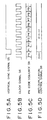
- Fig. 5 is a diagram describing the timing relation between the vertical sync signal S5, the clock signal S6, the PN code sequence S9 and the anti-duplication control signal sequence S8.
- the clock signal S6 is generated using the vertical sync signal S5 as a reference.
- the PN code sequence generator 7 is reset by the sync pulse of the vertical sync signal S5 so that one period of the PN code sequence (Fig. 5C) from a PN code P1 to a PN code PX occurs from the header of the sequence (PN code P1) every vertical interval.
- data in the anti-duplication control signal sequence S8 is changed from an anti-duplication control signal D(n) to an anti-duplication control signal D(n+1) in the next bit of the anti-duplication control signal sequence.
- one bit of data in the anti-duplication control signal is spectrally spread using the PN code sequence S9 generated with a period of one vertical interval.
- the adder 9 outputs an analog video signal S12 wherein the analog spectrally spread signal S11 is superimposed on the analog video signal S4.
- the analog video signal S12 may be supplied to the recording device 20 described hereafter, or it may be supplied to a monitor receiver not illustrated or the like.
- the analog spectrally spread signal S11 is a wideband, low level signal, so it does not cause deterioration of the video even when superimposed on the video signal.
- the recording device 20 which receives the analog video signal S12 from the playback device 10 and records the video signal will be described.
- the recording device 20 comprises an encoder 21, writer 22, reverse expander 23, PN code detector 24, vertical sync signal detector 25, PLL circuit 26, timing signal generator 27, detection controller (referred to hereafter as SS anti-duplication control signal detection controller) 28 which controls detection of the spectrally spread anti-duplication control signal, data determining unit 29 and A/D conversion circuit 291.
- the video signal is written by the recording device 20 on the recording medium 200.
- the video signal S12 from the playback device 10 is A/D converted by the A/D conversion circuit 291, and supplied to the encoder 21, reverse spectral expander 23, PN code detector 24 and vertical sync signal detector 25 as a digital video signal S21.
- the encoder 21 removes the sync signal from the digital video signal S21, and performs encoding operations such as data compression of the digital video signal. This generates a digital video signal S22 for recording on the recording medium 200, and this is supplied to the writer 22.
- the vertical sync signal detector 25 detects the vertical sync signal S23 from the video signal S21, and supplies it to the PLL circuit 26, timing signal generator 27 and SS anti-duplication control signal detection controller 28.
- the PLL circuit 26 generates a clock signal S24 used for performing reverse spectral spread based on the vertical sync signal S23.
- This clock signal S24 is supplied to the reverse spectral expander 23, PN code detector 24, timing signal generator 27, SS anti-duplication control signal detection controller 28 and data determining unit 29.
- the timing signal generator 27 generates various timing signals based on the vertical sync signal S23 and clock signal S24.
- a timing signal S25 which is generated by the timing signal generator 27 is supplied to the SS anti-duplication control signal detection controller 28.
- the SS anti-duplication control signal detection controller 28 controls the spectral expander 23, PN code detector 24 and data determining unit 29.
- the SS anti-duplication control signal detection controller 28 receives the vertical sync signal S23, clock signal S24 and timing signal S25, generates an enable signal S26 and an initialization signal S27, and controls the PN code detector 24 by supplying these signals to the PN code detector 24.
- the PN code detector 24 comprises for example a sliding scale correlation unit, and detects a PN code sequence which is spectrally spreading the anti-duplication control signal sequence superimposed on the video signal. The detection result is supplied to the SS anti-duplication control signal detection controller 28 as a signal S28.
- the signal S28 output by the PN code detector 24 indicates the strength of the correlation between the PN code sequence generated in the PN code detector 24 and the PN code sequence which is spectrally spreading the anti-duplication control signal sequence. Specifically, when there is a high correlation, the level of the signal S28 is high, and when there is a low correlation, the level of the signal S28 is low.
- the SS anti-duplication control signal detection controller 28 determines whether or not a PN code which is spectrally spreading the anti-duplication control signal has been detected, based on the level of the signal S28 from the PN code detector 24. When the level of the signal S28 is equal to or higher than a predetermined level, the SS anti-duplication control signal detection controller 28 determines that a PN code which is spectrally spreading the anti-duplication control signal has been detected, supplies a signal S29 which controls the start timing for generating a PN code sequence used for performing reverse spectral spread to the reverse expander 23, and supplies a control signal S30 for controlling the data determination timing to the data determining unit 29.
- the reverse expander 23 comprises the PN code sequence generator 231 and the reverse spread processor 232 as shown in Fig. 2.
- the PN code sequence generator 231 has an identical construction to that of the PN code generator 7 described hereabove referring to Fig. 3.
- the timing with which a PN code sequence S13 starts to be generated is controlled by the signal S29 from the SS anti-duplication control signal detection controller 28.
- the PN code sequence S31 is generated according to the clock signal S24, and is supplied to the reverse spread processor 232.
- the PN code sequence S31 has the same code pattern as the PN code sequence S9 used in the playback device 10, and is repetitively generated every vertical interval as in the case of the playback device 10.
- the reverse spread processor 232 performs reverse spectral spread using the PN code sequence S31 from the PN code sequence generator 231, and extracts an anti-duplication control signal sequence S32 which is superimposed on the video signal S21.
- the extracted anti-duplication control signal sequence S32 is supplied to the data determining unit 29.
- the data determining unit 29 is controlled by the control signal S30 from the SS anti-duplication control signal detection controller 28.
- the data determining unit 29 interprets the anti-duplication control signal S32, determines whether to permit or prohibit duplication, and generates control information S33 according to the result which is supplied to the writer 22.
- control information S33 is information for prohibiting write
- the writer 22 does not write the video signal S22 on the recording medium 200 so that the video signal supplied by the recording device 10 is prevented from being duplicated.
- the control information s33 permits duplication, the video signal S22 is written on the recording medium 200 so that the video signal from the playback device 10 is duplicated.
- the level of the signal S28 supplied to the anti-duplication control signal detection controller 28 from the PN code detector 24 is always equal to or less than a predetermined level in for example one vertical interval which is the period in which the PN code is detected, it is determined in the SS anti-duplication control signal detection controller 28 that the anti-duplication control signal is not superimposed on the video signal S21.
- the SS anti-duplication control signal detection controller 28 controls the data determining unit 29 by the control signal S30, generates a control signal to permit duplication, and supplies this signal to the writer 22 as the control signal S33.
- the video signal supplied by the playback device 10 is then duplicated on the recording medium 200.
- the SS anti-duplication control signal detection controller 28 starts detection of the PN code with a timing in synchronism with the vertical sync signal S23 detected from the video signal S21, as in the case of the playback device 10.
- the PN code sequence is started with effectively the same timing in the playback device 10 and recording device 20 relative to the video signal S21, the PN code sequence which is spectrally spreading the anti-duplication control signal sequence superimposed on the video signal S21 can be rapidly detected in the PN code generator 24.
- Reverse spectral spread in the reverse expander 23 can therefore also be rapidly and precisely performed.
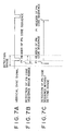
- Fig. 6 there may be a slight difference in the start timing of the PN code sequence in the video signal S12 from the playback device 10 (Fig. 6A), and the start timing of the PN code sequence which is generated in synchronism with the vertical sync signal S23 detected by the vertical sync signal detector 25 in the recording device 20 (Fig. 6B), due to the fact that the video signal S21 is affected by time axis errors arising in the transmitting system.
- the detection range of the PN code sequence which is spectrally spreading the anti-duplication control signal is set using the vertical sync signal as a reference, as shown in Fig. 6C.
- this detection range is set so that the header of the PN code sequence is always present. PN code detection in the recording device 20 is then performed within this set detection range.
- the detection range is set so that there is the same time span in the delay direction and the advance direction relative to the front edge of the vertical sync signal, as shown in Fig. 7.
- the PN code sequence can be rapidly detected even when the head P1 of the PN code sequence which is spectrally spreading the anti-duplication control signal sequence superimposed on the video signal, is shifted in the forward direction relative to the front edge of the vertical sync signal detected in the recording device 20 as shown in Fig. 7B, the PN code sequence can be rapidly detected.
- detection of the PN code is performed in the forward direction within a preset detection range.
- detection of the PN code is performed in the backward direction relative to the front edge of the vertical sync signal within a preset detection range. As detection needs to be performed only within this detection range, the required detection time may be reduced.
- detection of the PN code sequence may be performed until the header of the next PN code sequence is detected.
- this range may be set by the timing signal S25 generated by the timing signal generator 27.
- the detection range When the detection range is set as described hereabove, the range need only be very narrow compared to the case when the PN code sequence is detected for one period of the PN code sequence, so the detection time can be very short.
- Fig. 8 is a flowchart for the purpose of describing operation when the anti-duplication control signal which is spectrally spread and superimposed on the video signal S21 in the recording device 20, is detected.
- the SS anti-duplication control signal detection controller 28, PN code detector 24, reverse expander 23 and data determining unit 29 start the anti-duplication control signal detection shown in Fig. 8.
- the SS anti-duplication control signal detection controller 28 supplies the aforesaid enable signal S26 and initialization signal S27 to the PN code detector 24, and PN code detection is performed within the set detection range (step 101).
- the SS anti-duplication control signal detection controller 28 receives the signal S28 from the PN code detector 24, and it is determined whether or not the PN code sequence which is spectrally spreading the anti-duplication control signal sequence was detected (step 102).
- the SS anti-duplication control signal' detection controller 28 supplies the signal S29 which controls the PN code sequence start timing used in reverse spectral spread in the recording device 20 to the reverse expander 23, performs reverse spectral spread, and thereby extracts the anti-duplication control signal which is spectrally spread and superimposed on the video signal (step 103).
- the data determining unit 29 determines whether or not to permit duplication of the video signal and controls duplication of the video signal accordingly.
- the SS anti-duplication control signal detection controller 28 controls the data determining unit 29 so as to generate control information to permit duplication (step 104).
- This control information which permits duplication is supplied to the write unit 22, and the video signal supplied by the playback unit 10 is recorded on the recording medium 200.
- the video anti-duplication system by setting a start timing which starts generating the PN code sequence based on the sync signal in the video signal, generation of the PN code sequence may be started with effectively the same timing relative to the video signal in both the playback device 10 and recording device 20. Consequently, detection of the PN code superimposed on the video signal is performed rapidly, and the anti-duplication control signal superimposed on the video signal may be precisely and rapidly extracted.
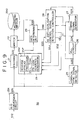
- Fig. 9 is a block diagram for describing an embodiment of the video recording device used as the video anti-duplication system of this invention.
- a recording device 30 receives a video signal from the playback device 10 which was described hereabove using Fig. 1, and this is recorded on the recording medium 200.
- PN code sequence starts to be generated with a timing in synchronism with a vertical sync signal extracted from the video signal.
- a PN code sequence can therefore be generated with effectively the same timing relative to the video signal in both the playback device 10 and the recording device 20.
- the timings of the PN code sequence in the received video signal S12 and the generated PN code sequence may actually be slightly different in the recording device due to time axis errors in the transmitting system.
- detection of the PN code sequence which is spectrally spreading the anti-duplication control signal sequence is performed for example over one period of the PN code sequence or within a preset detection range.
- the video signal is a highly precise signal, and when the PN code sequence is generated in synchronism with a vertical sync signal as described above, it may be assumed that there is no large deviation in sync between the playback device and recording device.
- "trial processing” is performed wherein the PN code sequence is generated with three predetermined timings, and reverse spectral spread is performed using the PN code sequence generated with each timing, so as to accelerate detection of the PN code sequence which is spectrally spreading the anti-duplication control signal sequence.
- the SS anti-duplication control signal detection controller 28 controls the reverse expander 23 and data determining unit 29.
- the SS anti-duplication control signal detection controller 28 receives the vertical sync signal S23, clock signal S24 and timing signal S25, generates an enable signal S51 for operating the reverse expander 23, an initialization signal S52 for controlling the start timing of the PN code sequence and another timing control signal S53, and supplies these signals to the reverse expander 23 so as to control it.
- the SS anti-duplication control signal detection controller 28 sets three timings for starting generation of the PN code sequence based on the vertical sync signal (Fig. 10A), generates PN code sequences for performing reverse spread with these timings, and performs reverse spectral spread as a trial process.
- three timings are used based on the front edge of the vertical sync signal (Fig. 10A), viz. an advanced timing (Fig. 10B), a timing which coincides with the front edge of the vertical sync signal (Fig. 10C) and a delayed timing (Fig. 10D).
- the start timing with which the PN code sequence used for performing reverse spectral spread as a trial process is generated is set according to the shift of PN code sequence between the playback device 10 and recording device 30. Specifically, the head of the PN code sequence which is spectrally spreading the anti-duplication control signal sequence lies between the delayed timing and the advanced timing as shown in Fig. 10, and is set so that the distance of these two timings on the time axis is a minimum.
- the reverse expander 23 comprises the PN code sequence generator 231 and the reverse spread processor 232 shown in Fig. 9.
- the PN code sequence generator 231 is activated by the enable signal S51 from the SS anti-duplication control signal detection controller 28, uses the initialization signal S52 as a timing signal for starting generation of the PN code sequence, generates a PN code sequence S54 used for performing reverse spread according to the timing control signal S53, and supplies this to the reverse spread processor 232.
- the PN code sequence S54 has the same code pattern as the PN code sequence S9 used in the playback device 10.
- the reverse spread processor 232 uses the PN code sequence S54 from the PN code sequence generator 231, the reverse spread processor 232 performs reverse spectral spread so as to extract the anti-duplication control signal sequence superimposed on the video signal.
- the reverse spectral expander 23 of this embodiment supplies a state signal S55 showing the result of reverse spectral spread to the SS anti-duplication control signal detection controller 28.
- the state signal S55 is a high level signal when there is a high correlation, and is a low level signal when there is a low correlation, between the PN code sequence which is spectrally spreading the anti-duplication control signal sequence and the PN code sequence S54 used for performing reverse spread, as shown in Fig. 10E.
- the SS anti-duplication control signal detection controller 28 controls the reverse expander 23 so as to generate the PN code sequence used for performing reverse spread with the aforesaid three timings (Fig. 10B, C, D) in order, performs reverse spectral spread, and extracts the result of reverse spectral spread as a trial process from the state signal S55.
- the SS anti-duplication control signal detection controller 28 considers the results of reverse spectral spread performed with the three timings, and sets the generation start timing of the PN code sequence accordingly.
- the SS anti-duplication control signal detection controller 28 sets a start timing T1 for generating the PN code sequence used for performing reverse spread between the front edge of the vertical sync signal and the delayed timing, as shown by the arrow T1 in Fig. 10E.
- the SS anti-duplication control signal detection controller 28 generates a PN code sequence for reverse spread using the timing signal T1 in order to control the reverse expander 23. The result is supplied to the SS anti-duplication control signal detection controller 28 as the signal S55, and the SS anti-duplication control signal detection controller 28 adjusts the generation start timing of the PN code sequence used for performing reverse spread so as to lie between the front edge of the vertical sync signal and the advanced timing according to the level of the signal S55.
- an extracted anti-duplication control signal sequence S57 is supplied to the data determining unit 29.
- the data determining unit 29 interprets the anti-duplication control signal S57 under the control of a signal S56 from the SS anti-duplication control signal detection controller 28, determines whether duplication is permitted or prohibited, generates the control signal S33 according to the result, and supplies it to the writer 22.
- control signal S33 is information which prohibits write
- the writer 22 does not permit writing of the video signal S22 on the recording medium 200 so that duplication of the video signal from the playback device 10 is prevented.
- the control signal S33 does permit duplication
- the video signal S22 is written on the recording medium 200 so as to duplicate the video signal from the playback device 10.
- the SS anti-duplication control signal detection controller 28 determines that an anti-duplication control signal is not superimposed on the video signal S21.
- the SS anti-duplication control signal detection controller 28 controls the data determining unit 29 by the control signal S56 so as to generate a control signal permitting duplication, and this is supplied to the writer 22 as the control signal S33. In such a case, therefore, the video signal supplied by the playback device 10 is duplicated on the recording medium 200.
- Fig. 11 is a flowchart for the purpose of describing operation when an anti-duplication control signal that is spectrally spread and superimposed on the video signal S21, is detected in the recording device 30 of this embodiment.
- the SS anti-duplication control signal detection controller 28, reverse expander 23 and data determining unit 29 start detection of the anti-duplication control signal shown in Fig. 10.
- the SS anti-duplication control signal detection controller 28 controls the reverse expander 23 so as to generate PN code sequences with the three timings shown in Fig. 10B, C, D, performs reverse spectral spread, and supplies the result to the SS anti-duplication control signal detection controller 28 as the signal S55.
- the SS anti-duplication control signal detection controller 28 performs a correlation value computation based on the result of reverse spectral spread performed with these three timings (step 201).
- the SS anti-duplication control signal detection controller 28 determines the direction of the shift of the PN code sequence according to the result of this correlation value computation (step 202).
- the SS anti-duplication control signal detection controller 28 sets the generation start timing of the PN code sequence used for performing reverse spread based on the results of the steps 201, 202 (step 203).
- the reverse expander 23 is then controlled so as to generate the PN code sequence used for performing reverse spread with the set generation start timing, performs reverse spectral spread, and extracts the anti-duplication control signal sequence superimposed on the video signal (step 204).
- the SS anti-duplication control signal detection controller 28 receives the signal S55 from the reverse expander 23, and determines whether or not the anti-duplication control signal superimposed on the video signal was extracted as a detectable signal having at least a predetermined level (step 205).
- the SS anti-duplication control signal detection controller 28 controls the data determining unit 29 so as to generate a control signal controlling the writer 22 according to the extracted anti-duplication control signal (step 206), and this signal is supplied to the writer 22 so as to control duplication of the video signal from the playback device 10.
- the SS anti-duplication control signal detection controller 28 determines whether or not to vary the generation start timing of the PN code sequence (step 207).
- the determining process of the step 205 in this example is a process which determines whether or not a PN code sequence which is spectrally spreading the anti-duplication control signal lies between the advanced timing shown in Fig. 10B and the delayed timing shown in Fig. 10D, based on a trial process in which spectral spread is performed by a PN code sequence generated with three different start timings as described using Fig. 11.
- step 207 When it is determined in the determining process of the step 207 that there is no PN code sequence which is spectrally spreading the anti-duplication control signal sequence, based on the aforesaid trial process, it is determined that an anti-duplication control signal is not superimposed on the video signal, and the data determining unit 29 is controlled so as to generate a control signal permitting duplication (step 208).
- This control signal is supplied to the writer 22 so as to inform the writer 22 that duplication is permitted.
- the processing of the step S204 and subsequent steps is repeated, and the generation start timing of the PN code sequence used for performing reverse spread is varied so that it lies between the front edge of the vertical sync signal (Fig. 10C) and the delayed timing (Fig. 10D), which is the code shift direction determined in the step 202.
- a PN code sequence is generated with three predetermined timings, and by performing reverse spectral spread, a correlation value is found between the PN code sequence generated with each timing and the PN code sequence which is spectrally spreading the anti-duplication control signal.
- a PN code sequence for performing reverse spectral spread having a higher correlation with the PN code sequence used for spectrally spreading the anti-duplication control signal, can therefore be generated.
- reverse spectral spread was performed using three different timings as shown in Fig. 10, however the invention is not limited to this arrangement, and the correlation value computation may be performed by setting at least two timings, i.e. an advanced timing and a delayed timing. Moreover, by performing the correlation value computation using a plurality of timings, e.g. four or five timings, for generating the PN code sequence, a PN code sequence may be generated that has a stronger correlation with the PN code sequence which is spectrally spreading the anti-duplication control signal than if the correlation value computation is performed with a smaller number of timings.
- a PN code sequence may be generated that has a stronger correlation with the PN code sequence which is spectrally spreading the anti-duplication control signal than if the correlation value computation is performed with a smaller number of timings.
- a combination may also be used of the aforesaid method wherein a time-limited range is set based on the video sync signal in order to detect the PN code sequence which is spectrally spreading the anti-duplication control signal, and the method of this embodiment wherein at least two timings are defined relative to the video sync signal.
- a PN code sequence for performing reverse spectral spread is generated with each timing, correlation values are found for each timing, and the generation start timing of the PN code sequence used for performing reverse spectral spread is set.
- the PN code sequence may be generated with a timing in synchronism with the vertical sync signal so as to perform reverse spectral spread, and extract the anti-duplication control signal superimposed on the video signal.
- the spectrally spread anti-duplication control signal may also be superimposed on the playback device 10 prior to D/A conversion, and D/A conversion performed later.
- a vertical sync signal was used, but the invention is not limited to this arrangement, it being possible to generate the PN code sequence start timing control signal and clock signal using a horizontal sync signal.
- the PN code sequence start timing was controlled using a vertical sync signal, but the invention is not limited to this configuration.
- a start timing signal may be generated showing the start of a PN code sequence shifted by a plurality of clock intervals based on the front edge of the vertical sync signal, and if this signal is used, generation of the PN code sequence can always be started at a plurality of clock intervals from the front edge of the vertical sync signal. It will be understood that the start timing of the PN code sequence may be similarly shifted when a horizontal sync signal is used.
- the signal output by the encoder 21 may be supplied to the vertical sync signal detector 25 as a signal for detecting the vertical sync signal.
- a horizontal sync signal may be used in the recording devices 20 and 30 as in the playback device 10.
- generation of the PN code sequence was started every vertical interval, but the invention is not limited to this arrangement.
- the PN code sequence may be initiated every integral number of vertical or horizontal intervals, or every fraction of an interval.
- generation of the PN code sequence may be started every plurality of vertical intervals, such as every two or three vertical intervals, or every fractional interval obtained by dividing one vertical interval into a plurality of parts, such as every 1/2 or 1/3 vertical interval.
- the anti-duplication control signal added to the video signal of the recording medium 100 was extracted, spectrally spread and then superimposed on the video signal supplied to the recording device, but alternatively, the spectrally spread anti-duplication control signal may first be superimposed on the video signal prior to recording on the recording medium.
- the anti-duplication control signal is spectrally spread using a PN code sequence which starts to be generated with a timing based on a vertical sync signal or a horizontal sync signal, which is a video sync signal.
- This spectrally spread anti-duplication control signal is first superimposed on the video signal, and the video signal is then recorded on the recording medium.
- reverse spectral spread may be performed using a PN code sequence which starts to be generated with the same timing and the same phase as the PN code sequence used for spectral spread of the anti-duplication control signal which was first superimposed on the video signal recorded on the recording medium as described hereabove.
- an anti-duplication control signal generator may be provided in the playback device, the anti-duplication control signal generated in the playback device may be spectrally spread using a PN code sequence generated with a start timing based on the video sync signal as described hereabove, and this spectrally spread anti-duplication control signal superimposed on the output video signal.
- the anti-duplication control signal which is generated by the anti-duplication control signal generator of the playback device, spectrally spread and superimposed on the video signal may be extracted in the recording device and used to control duplication.
- the playback device has an anti-duplication control signal generator to generate a PN code sequence, spectrally expand the anti-duplication control signal and superpose it on the video signal in this manner, duplication may be effectively controlled even when there is no anti-duplication control signal on the the recording medium itself.
- the playback device 10, recording device 20 and recording device 30 were described as DVD devices, but the invention is not limited to this case.
- the invention may also be applied to VTR, digital VTR, or to video disc or video CD playback and recording devices.
- this invention may be applied equally well to analog instruments such as analog VTR, and digital instruments such as DVD devices.
- the anti-duplication controller was described as a DVD playback or recording device, but the invention is not limited to playback or recording devices.
- the invention may be applied also to the case where a video output device according to this invention is used as a device for outputting television signals in a broadcasting station, and a spectrally spread anti-duplication control signal is superimposed on the transmitted television signal.
- reverse spectral spread may be performed so as to extract the anti-duplication control signal sequence superimposed on the video signal, and control duplication of the video signal based on this anti-duplication control signal.
- this invention may be applied to devices for outputting and receiving video signals when analog video signals are transmitted and received, such as in the case of cable television.
- spectral spread and reverse spectral spread of an anti-duplication control signal are performed using an spread code which is repeated with a predetermined period in synchronism with a video sync signal.
- generation of the spread code can be started with the same timing relative to the video sync signal on both the output side and the receiving side of a video signal.
- Synchronism may thus rapidly be achieved on the receiving side between the spread code which is spectrally spreading the anti-duplication control signal and the spread code used for performing reverse spectral spread, and the anti-duplication control signal superimposed on the video signal may be precisely and rapidly extracted on the receiving side.
- Synchronism between the spread code which is spectrally spreading the anti-duplication control signal and the spread code used for performing reverse spectral spread may be more rapidly achieved, and reverse spectral spread performed precisely and rapidly, by detecting the spread code which is spectrally spreading the anti-duplication control signal within a time-limited range based on the video sync signal.
- Synchronism between the spread code which is spectrally spreading the anti-duplication control signal and the spread code used for performing reverse spectral spread may also be more rapidly achieved by generating the spread code with at least two timings, i.e. an advanced timing and a delayed timing, relative to the video sync signal, performing reverse spectral spread, and detecting a correlation with the spread code which is spectrally spreading the anti-duplication control signal.
Landscapes
- Engineering & Computer Science (AREA)
- Multimedia (AREA)
- Signal Processing (AREA)
- Television Signal Processing For Recording (AREA)
- Signal Processing For Digital Recording And Reproducing (AREA)
- Two-Way Televisions, Distribution Of Moving Picture Or The Like (AREA)
- Signal Processing Not Specific To The Method Of Recording And Reproducing (AREA)
Claims (18)
- Récepteur vidéo comprenant :un moyen de réception pour recevoir un signal vidéo (S12) sur lequel un signal d'information additionnelle étalé spectralement (S11) est superposé ;un moyen de détection de synchronisation (25) pour détecter un signal de synchronisation (S23) dans ledit signal vidéo reçu (S12) ;un moyen de génération de code étalé (231) pour générer un code étalé spectralement (S31) moyennant au moins deux cadencements prédéterminés suivant des directions d'avance et de retard par rapport audit signal de synchronisation détecté (S23), ledit code étalé étant pour réaliser un étalement spectral inverse ;un moyen de calcul de corrélation pour calculer une valeur de corrélation entre lesdits codes étalés spectralement qui sont utilisés pour réaliser un étalement spectral inverse, comme généré à l'aide desdits au moins deux cadencements, et ledit code d'étalement spectral (S31) dans ledit signal vidéo reçu ; etun moyen d'étalement spectral inverse (232) pour extraire ledit signal d'information additionnelle (S8) à partir dudit signal vidéo en réalisant un étalement spectral inverse sur ledit signal vidéo reçu en utilisant ledit code étalé spectralement (S31) à un cadencement sur la base du résultat dudit moyen de calcul de corrélation.
- Récepteur vidéo selon la revendication 1, comprenant en outre :un moyen de calcul de cadencement pour calculer un cadencement de début (T1) entre lesdits au moins deux cadencements prédéterminés.
- Récepteur vidéo selon la revendication 1 ou 2, dans lequel y a au moins trois cadencements prédéterminés.
- Récepteur vidéo selon la revendication 3, dans lequel y a quatre cadencements prédéterminés.
- Récepteur vidéo selon la revendication 3, dans lequel y a cinq cadencements prédéterminés.
- Récepteur vidéo selon l'une quelconque des revendications précédentes, dans lequel ledit signal de synchronisation (S23) dans ledit signal vidéo est un signal de synchronisation verticale ou un signal de synchronisation horizontale.
- Récepteur vidéo selon l'une quelconque des revendications précédentes, dans lequel ledit signal d'information additionnelle (S8) est un signal de commande de duplication pour empêcher l'enregistrement dudit signal vidéo ou pour limiter le nombre d'occurrences selon lesquelles ledit signal vidéo est enregistré sur un support d'enregistrement (200) et ledit récepteur comprend en outre un moyen de commande de duplication (29) pour commander l'enregistrement dudit signal vidéo sur ledit support d'enregistrement (200) sur la base dudit signal de commande de duplication extrait (S32).
- Récepteur de signal vidéo selon l'une quelconque des revendications précédentes, dans lequel un cadencement de génération dudit code étalé spectralement (S31) pour réaliser un étalement spectral inverse est réglé de manière à s'inscrire dans la plage d'un intervalle de cadencement prédéterminé suivant les directions d'avance et de retard par rapport audit signal de synchronisation détecté (S23).
- Système anti-duplication vidéo comprenant un dispositif de lecture vidéo (10) pour reproduire un signal vidéo (S12) et un dispositif d'enregistrement vidéo (20) pour recevoir ledit signal vidéo reproduit (S12) et pour l'enregistrer sur un support d'enregistrement (200), dans lequel ledit dispositif de lecture vidéo (10) comprend :ledit dispositif d'enregistrement vidéo (20) présente les caractéristiques du récepteur vidéo selon l'une quelconque des revendications précédentes.un moyen de génération de code d'étalement (7) pour générer un code étalé spectralement (S9) pour réaliser un étalement spectral en synchronisation avec un signal de synchronisation (S5) dans ledit signal vidéo ;un moyen d'étalement spectral (8, 192) pour étaler spectralement un signal de commande de duplication vidéo (S8) pour commander l'enregistrement dudit signal vidéo sur ledit support d'enregistrement en utilisant ledit code étalé spectralement (S9) pour réaliser un étalement spectral ;un moyen de superposition (9) pour superposer ledit signal de commande anti-duplication étalé spectralement (S11) sur ledit signal vidéo (S4); etun moyen d'émission en sortie pour émettre en sortie, en tant que signal vidéo analogique (S12), ledit signal vidéo sur lequel ledit signal d'information additionnelle étalé spectralement (S11) a été superposé ; et
- Système de superposition et d'extraction d'information comprenant un dispositif de superposition d'information (7, 8, 9) pour superposer un signal d'information additionnelle (S8) sur un signal vidéo (S4) et un dispositif d'extraction d'information (291, 25, 231, 232) pour extraire ladite information additionnelle (S8) à partir dudit signal vidéo (S12), dans lequel ledit dispositif de superposition d'information comprend :dans lequel ledit dispositif d'extraction d'information comprend les caractéristiques du récepteur vidéo selon l'une quelconque des revendications 1 à 8.un moyen de génération de code d'étalement (7) pour générer un code étalé spectralement (S9) pour réaliser un étalement spectral en synchronisation avec un signal de synchronisation (S5) dans ledit signal vidéo (S4);un moyen d'étalement spectral (8) pour étaler spectralement ledit signal d'information additionnelle (S8) destiné à être superposé sur ledit signal vidéo (S4) en utilisant ledit code étalé spectralement (S9) pour réaliser un étalement spectral ; etun moyen de superposition (9) pour superposer ledit signal d'information additionnelle étalé spectralement (S11) sur ledit signal vidéo (S4); et
- Procédé de réception de signal vidéo comprenant les étapes de :réception d'un signal vidéo (S12) sur lequel un signal d'information additionnelle étalé spectralement (S11) est superposé ;détection d'un signal de synchronisation (S23) dans ledit signal vidéo reçu ; etextraction d'un signal d'information additionnelle (S32) à partir dudit signal vidéo en générant un code étalé spectralement (S31) moyennant au moins deux cadencements prédéterminés suivant les directions d'avance et de retard par rapport audit signal de synchronisation détecté (S23), ledit code étalé étant pour réaliser un étalement spectral inverse ;calcul d'une valeur de corrélation entre lesdits codes étalés spectralement qui sont utilisés pour réaliser un étalement spectral inverse, comme généré moyennant lesdits au moins deux cadencements, et ledit code étalé spectralement (S31) dans ledit signal vidéo reçu ; etréalisation d'un étalement spectral inverse sur ledit signal vidéo reçu en utilisant ledit code étalé spectralement (S31) à un cadencement sur la base desdites valeurs de corrélation.
- Procédé de réception de signal vidéo selon la revendication 11, dans lequel ledit cadencement (T1) est entre lesdits au moins deux cadencements prédéterminés.
- Procédé de réception de signal vidéo selon la revendication 11 ou 12, dans lequel il y a au moins trois cadencements prédéterminés.
- Procédé de réception de signal vidéo selon la revendication 13, dans lequel il y a quatre cadencements prédéterminés.
- Procédé de réception de signal vidéo selon la revendication 13, dans lequel il y a cinq cadencements prédéterminés.
- Procédé de réception de signal vidéo selon l'une quelconque des revendications 11 à 15, dans lequel ledit signal de synchronisation (S5) dans ledit signal vidéo (S4) est un signal de synchronisation verticale ou un signal de synchronisation horizontale.
- Procédé de réception de signal vidéo selon l'une quelconque des revendications 11 à 16, dans lequel ledit signal d'information additionnelle (S8) est un signal de commande de duplication pour empêcher l'enregistrement dudit signal vidéo ou pour limiter le nombre d'occurrences selon lesquelles ledit signal vidéo est enregistré sur un support d'enregistrement (200).
- Procédé de réception de signal vidéo selon l'une quelconque des revendications 11 à 15, dans lequel un cadencement de génération dudit code étalé spectralement (S31) pour réaliser un étalement spectral inverse est réglé de manière à s'inscrire dans la plage d'un intervalle de cadencement prédéterminé suivant les directions d'avance et de retard par rapport audit signal de synchronisation détecté (S23).
Applications Claiming Priority (3)
| Application Number | Priority Date | Filing Date | Title |
|---|---|---|---|
| JP30243996A JP3671992B2 (ja) | 1996-10-28 | 1996-10-28 | 映像信号受信装置および映像信号受信方法 |
| JP30243996 | 1996-10-28 | ||
| JP302439/96 | 1996-10-28 |
Publications (3)
| Publication Number | Publication Date |
|---|---|
| EP0838949A2 EP0838949A2 (fr) | 1998-04-29 |
| EP0838949A3 EP0838949A3 (fr) | 1998-05-06 |
| EP0838949B1 true EP0838949B1 (fr) | 2003-03-26 |
Family
ID=17908954
Family Applications (1)
| Application Number | Title | Priority Date | Filing Date |
|---|---|---|---|
| EP97308341A Expired - Lifetime EP0838949B1 (fr) | 1996-10-28 | 1997-10-21 | Méthode de transmission de vidéo, méthode et dispositif de protection contre la copie de vidéo |
Country Status (5)
| Country | Link |
|---|---|
| US (1) | US6389137B1 (fr) |
| EP (1) | EP0838949B1 (fr) |
| JP (1) | JP3671992B2 (fr) |
| CN (1) | CN1161996C (fr) |
| DE (1) | DE69720136T2 (fr) |
Families Citing this family (7)
| Publication number | Priority date | Publication date | Assignee | Title |
|---|---|---|---|---|
| JP3594063B2 (ja) | 1997-01-13 | 2004-11-24 | ソニー株式会社 | 情報信号伝送方法および複製防止制御方法 |
| JP2000013585A (ja) * | 1998-06-19 | 2000-01-14 | Sony Corp | 付加情報の重畳装置、付加情報の重畳方法、画像情報記録装置および画像情報記録方法 |
| WO2000041056A2 (fr) * | 1999-01-06 | 2000-07-13 | Digital Video Express, L.P. | Systeme et procede de distribution de contenu numerique |
| JP2000324468A (ja) * | 1999-05-14 | 2000-11-24 | Sony Corp | 映像信号出力装置、映像信号入力装置、スクランブル方法、デスクランブル方法 |
| JP2001069583A (ja) * | 1999-08-25 | 2001-03-16 | Sony Corp | 情報信号伝送方法、情報信号伝送システム、情報信号送信装置および情報信号受信装置 |
| JP3990853B2 (ja) * | 2000-03-24 | 2007-10-17 | 株式会社トリニティーセキュリティーシステムズ | デジタルコピー防止処理装置、その装置により処理されたデジタルデータを記録した再生可能な記録媒体、デジタルコピー防止処理方法、その方法をコンピュータに実行させるプログラムを記録したコンピュータ読み取り可能な記録媒体およびその方法により処理されたデジタルデータを記録した再生可能な記録媒体 |
| US20050189444A1 (en) * | 2004-03-01 | 2005-09-01 | Meyer Products, Inc. | Wireless control system for a spreader |
Family Cites Families (27)
| Publication number | Priority date | Publication date | Assignee | Title |
|---|---|---|---|---|
| US3984624A (en) | 1974-07-25 | 1976-10-05 | Weston Instruments, Inc. | Video system for conveying digital and analog information |
| US5363108A (en) * | 1984-12-03 | 1994-11-08 | Charles A. Phillips | Time domain radio transmission system |
| US5177604A (en) * | 1986-05-14 | 1993-01-05 | Radio Telcom & Technology, Inc. | Interactive television and data transmission system |
| US4969041A (en) | 1988-09-23 | 1990-11-06 | Dubner Computer Systems, Inc. | Embedment of data in a video signal |
| US5062122A (en) * | 1988-09-28 | 1991-10-29 | Kenwood Corporation | Delay-locked loop circuit in spread spectrum receiver |
| US5134496A (en) | 1989-05-26 | 1992-07-28 | Technicolor Videocassette Of Michigan Inc. | Bilateral anti-copying device for video systems |
| US5499265A (en) * | 1989-08-07 | 1996-03-12 | Omnipoint Data Company, Incorporated | Spread spectrum correlator |
| CH679718A5 (fr) * | 1989-10-19 | 1992-03-31 | Ascom Zelcom Ag | |
| JPH043540A (ja) * | 1990-04-19 | 1992-01-08 | Yamaha Corp | スペクトラム拡散通信装置 |
| WO1993004432A2 (fr) * | 1991-08-16 | 1993-03-04 | Multichip Technology | Systeme de memoire dynamique rapide |
| JPH0646032A (ja) * | 1991-10-24 | 1994-02-18 | Ricoh Co Ltd | スペクトル拡散通信方式 |
| US5243423A (en) * | 1991-12-20 | 1993-09-07 | A. C. Nielsen Company | Spread spectrum digital data transmission over TV video |
| ATE207278T1 (de) * | 1992-01-08 | 2001-11-15 | Broadband Innovations Inc | Mehrkanal-fernsehsignal ver- und entschlüsselungssystem und -verfahren |
| US5276859A (en) * | 1992-03-09 | 1994-01-04 | Cabletron Systems, Inc. | Accelerated token ring network |
| TW221507B (fr) | 1992-06-16 | 1994-03-01 | Matsushita Electric Industrial Co Ltd | |
| US5533046A (en) * | 1992-10-08 | 1996-07-02 | Lund; Vanmetre | Spread spectrum communication system |
| US5375140A (en) * | 1992-11-24 | 1994-12-20 | Stanford Telecommunications, Inc. | Wireless direct sequence spread spectrum digital cellular telephone system |
| US5596599A (en) * | 1992-12-04 | 1997-01-21 | Canon Kabushiki Kaisha | Spread spectrum receiving apparatus |
| JPH06315020A (ja) * | 1993-01-06 | 1994-11-08 | Ricoh Co Ltd | スペクトル拡散通信方式 |
| US5546424A (en) * | 1993-06-30 | 1996-08-13 | Casio Computer Co., Ltd. | Spread spectrum communication system |
| US5488627A (en) * | 1993-11-29 | 1996-01-30 | Lexmark International, Inc. | Spread spectrum clock generator and associated method |
| JPH08221315A (ja) * | 1995-02-15 | 1996-08-30 | Hitachi Ltd | 情報処理装置 |
| JPH08288928A (ja) * | 1995-04-14 | 1996-11-01 | Toshiba Corp | スペクトラム拡散通信装置 |
| US5867489A (en) * | 1996-05-29 | 1999-02-02 | Lockheed Martin Corp. | Method and apparatus for TDMA slot synchronization with precision ranging |
| US5862133A (en) * | 1996-08-02 | 1999-01-19 | Golden Bridge Technology | Packet-switched spread-spectrum system |
| US5848155A (en) * | 1996-09-04 | 1998-12-08 | Nec Research Institute, Inc. | Spread spectrum watermark for embedded signalling |
| US5930366A (en) * | 1997-08-29 | 1999-07-27 | Telefonaktiebolaget L M Ericsson | Synchronization to a base station and code acquisition within a spread spectrum communication system |
-
1996
- 1996-10-28 JP JP30243996A patent/JP3671992B2/ja not_active Expired - Fee Related
-
1997
- 1997-10-15 US US08/951,027 patent/US6389137B1/en not_active Expired - Fee Related
- 1997-10-21 DE DE69720136T patent/DE69720136T2/de not_active Expired - Fee Related
- 1997-10-21 EP EP97308341A patent/EP0838949B1/fr not_active Expired - Lifetime
- 1997-10-27 CN CNB97114172XA patent/CN1161996C/zh not_active Expired - Fee Related
Also Published As
| Publication number | Publication date |
|---|---|
| US6389137B1 (en) | 2002-05-14 |
| CN1195951A (zh) | 1998-10-14 |
| EP0838949A3 (fr) | 1998-05-06 |
| JPH10136305A (ja) | 1998-05-22 |
| EP0838949A2 (fr) | 1998-04-29 |
| DE69720136D1 (de) | 2003-04-30 |
| CN1161996C (zh) | 2004-08-11 |
| DE69720136T2 (de) | 2004-02-05 |
| JP3671992B2 (ja) | 2005-07-13 |
Similar Documents
| Publication | Publication Date | Title |
|---|---|---|
| US6487363B1 (en) | Video duplication control signal, video playback device, video recording device, information superimposing and extracting device and video recording medium | |
| US6370320B1 (en) | Information output device, information recording device, information duplication control system and recording medium of the same | |
| US6636551B1 (en) | Additional information transmission method, additional information transmission system, information signal output apparatus, information signal processing apparatus, information signal recording apparatus and information signal recording medium | |
| US6389220B2 (en) | Information signal duplication control system | |
| EP0843473B1 (fr) | Système de commande de reproduction de signal d'information | |
| US7027100B2 (en) | Video signal transmission device, video signal output device, video signal reception device, video signal duplication control system, information superimposing/extraction device, and image recording medium | |
| US6453118B2 (en) | Information transmission method, information duplication prohibiting method, information duplication prohibition device and information crevording medium | |
| EP0838949B1 (fr) | Méthode de transmission de vidéo, méthode et dispositif de protection contre la copie de vidéo | |
| US6356705B1 (en) | Video signal transmission method, superimposed information extraction method, video signal output device, video signal recording device, and video signal recording medium | |
| US6330393B1 (en) | Method and device for information anti-duplication | |
| EP0848550B1 (fr) | Procédé de transmission de signal vidéo, procédé d'extraction d'information superposée, dispositif de sortie de signal vidéo, dispositif d'enrégistrement de signal vidéo, et moyen d'enrégistrement de signal vidéo | |
| JPH10336604A (ja) | 付加情報重畳装置 | |
| JPH10191244A (ja) | 映像信号伝送方法、重畳情報抽出方法、映像信号出力装置、映像信号受信装置および映像記録媒体 | |
| JPH10210431A (ja) | 映像信号伝送方法、重畳情報抽出方法、映像信号出力装置、映像信号受信装置および映像信号記録媒体 |
Legal Events
| Date | Code | Title | Description |
|---|---|---|---|
| PUAI | Public reference made under article 153(3) epc to a published international application that has entered the european phase |
Free format text: ORIGINAL CODE: 0009012 |
|
| PUAL | Search report despatched |
Free format text: ORIGINAL CODE: 0009013 |
|
| AK | Designated contracting states |
Kind code of ref document: A2 Designated state(s): DE FR GB |
|
| AK | Designated contracting states |
Kind code of ref document: A3 Designated state(s): AT BE CH DE DK ES FI FR GB GR IE IT LI LU MC NL PT SE |
|
| RHK1 | Main classification (correction) |
Ipc: H04N 5/913 |
|
| 17P | Request for examination filed |
Effective date: 19981006 |
|
| AKX | Designation fees paid |
Free format text: DE FR GB |
|
| RBV | Designated contracting states (corrected) |
Designated state(s): DE FR GB |
|
| 17Q | First examination report despatched |
Effective date: 20020128 |
|
| GRAH | Despatch of communication of intention to grant a patent |
Free format text: ORIGINAL CODE: EPIDOS IGRA |
|
| GRAH | Despatch of communication of intention to grant a patent |
Free format text: ORIGINAL CODE: EPIDOS IGRA |
|
| GRAA | (expected) grant |
Free format text: ORIGINAL CODE: 0009210 |
|
| AK | Designated contracting states |
Designated state(s): DE FR GB |
|
| REG | Reference to a national code |
Ref country code: GB Ref legal event code: FG4D |
|
| REF | Corresponds to: |
Ref document number: 69720136 Country of ref document: DE Date of ref document: 20030430 Kind code of ref document: P |
|
| ET | Fr: translation filed | ||
| PLBE | No opposition filed within time limit |
Free format text: ORIGINAL CODE: 0009261 |
|
| STAA | Information on the status of an ep patent application or granted ep patent |
Free format text: STATUS: NO OPPOSITION FILED WITHIN TIME LIMIT |
|
| 26N | No opposition filed |
Effective date: 20031230 |
|
| PGFP | Annual fee paid to national office [announced via postgrant information from national office to epo] |
Ref country code: DE Payment date: 20081016 Year of fee payment: 12 |
|
| PGFP | Annual fee paid to national office [announced via postgrant information from national office to epo] |
Ref country code: FR Payment date: 20081014 Year of fee payment: 12 |
|
| PGFP | Annual fee paid to national office [announced via postgrant information from national office to epo] |
Ref country code: GB Payment date: 20081015 Year of fee payment: 12 |
|
| REG | Reference to a national code |
Ref country code: FR Ref legal event code: ST Effective date: 20100630 |
|
| PG25 | Lapsed in a contracting state [announced via postgrant information from national office to epo] |
Ref country code: FR Free format text: LAPSE BECAUSE OF NON-PAYMENT OF DUE FEES Effective date: 20091102 Ref country code: DE Free format text: LAPSE BECAUSE OF NON-PAYMENT OF DUE FEES Effective date: 20100501 |
|
| PG25 | Lapsed in a contracting state [announced via postgrant information from national office to epo] |
Ref country code: GB Free format text: LAPSE BECAUSE OF NON-PAYMENT OF DUE FEES Effective date: 20091021 |